Contents
Cover
 After the model is complete, and you have checked that the model geometry is correct, then select your materials, simulate their application to your model, and extract detailed cutting lists and supplier orders.

A panel layout on this moderately complex roof, with complete installation details that matches the material cutting list IN MINUTES!
 Select Tile
(This is used when your preference is set to Tiles database, as distinct from Tiles+ database. Refer to the Set-Up > Preference Settings > System Preferences command to see how you set the preference to Tiles database or Tiles+ database.

This command lets you select the tile for the job as well as other tiled roof parameters. When you first select Select-Tile, the Select the tile dialog box is displayed.
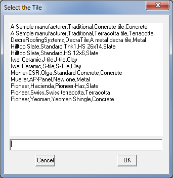
Once you have selected a tile, click [OK] and the Current Tile dialog box appears:

This dialog reports to you the coverage as well as other geometric values for the selected tile. Refer to Set-Up > Tiles command to see how you can define and change a tile definition.
Colour This drop down box lets you select the colour for this tile from a list of colours provided by that supplier. Trim tiles which are set to “From field tile” will also adopt this colour.
Hip-finish Hip Type is one of, Bed and point (normal), Seal and Butt
Ridge- finish Ridge Type is one of Bed and point (normal), Seal and Butt
Gable- finish Gable Type is one of Dry (normal), Bed and point, Seal and Barge ridge (this is actually a different tile whose cost needs to be provided under cover costs)
Valley- finish Valley Type is one of Dry (normal), Bed and point and Seal
Flexible pointing This is either Yes or No
Pay rate schedule Clicking in this field will display a list of the pay rate schedules you have defined. Refer to the Set Up > Tile-Pay command to see how you define a pay rate schedule.
Batten To select a batten for the job, select the appropriate size from the Batten combo box. These battens are read directly from the batten materials database. You can define a new batten using the Cover > Flashings command. See below for the operation of the [Apply To] button:
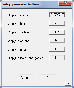
Apply To This button lets you select where you want extra battens to be estimated around the perimeter of each roof plane. Initially no perimeter battens are estimated
You will not see these battens on the drawing but the lengths of the relevant roof lines are added to estimate the total length of battens required.
Counter batten This will be the counter batten you want to use.
Spacing This is the spacing of the counter battens. It defaults to be the rafter spacing you set under Job-Details.
Underlay This is the underlay you want to use. It is assumed that you want to apply the underlay to the entire roof. If you want to apply it partially, then refer to the Cover > Underlay command. To define an underlay to appear in this list, you must define a new insulation using Set-Up > Insulation with the name of “Sarking” or “Underlay”. Sarking or Underlay can only be selected by having roof planes with a material applied, be it either metal or tiles. Indeed the digitizing of partial sarking etc. requires these planes to exist and have a material applied.
Starter course Clicking this field will open a list of shingles or shakes you can use as the starter course. The starter course is applied to all eaves as well as to rake edges when using shingles. This field only appears in the Select-Shingle and Select-Shake commands.
Fall protection Here you can define the fall protection you want to use. To get a fall protection item listed, you must define a new user-defined flashing with the Finish set to “Fall Protection”. You do this with the Set-Up > Flashing command.
FP Pitch Break This is the fall protection pitch break value. The system automatically assumes that fall protection is applied to all eaves for storeys 2 and above and on first storey roofs where the pitch of the roof is greater than this value. If you want to apply fall protection to other eave lines, then refer to the Cover > Fall-protection command.
Accessories The accessories button takes you to the pre-defined accessories for the curently selected tile profile.

Set Defaults To save the current settings as the default for most of your jobs, thus saving time re-selecting the various options, select the [Set Defaults] button as shown below. The software saves the current selection to a file called TileDef.csv and is read each time you select a tile.

At the bottom of the dialog, a message is written to inform you which estimation method is used (area or coursing). If you generate coursing lines (see later), the estimation method will become, ‘coursing’.
To cancel the tile selection click [Cancel]
To change the tile selection, click [Change].
To accept the tile selection, click [OK].
This then becomes the cover material for all the tile roof planes in the model.
Coursing
Selecting this button lets you perform an estimate by simulating the laying of the tiles course by course. If you do not want to estimate by coursing, you can ignore this step and the estimate will default to the area method ie pieces per square metre (or square).
Default Tiling Estimation Method the estimating method quantifying tiles – the options for estimating tiles are by Area or by Course. Area calculates quantity based on pieces or bundles per square and Coursing actually lays the pieces course by course on the roof model from the eave upwards, and then counts the pieces. Waste, if defined, is applied later, during the cost reporting operation of Supply Only or Supply and Install. The [Select Tile] dialog displays the method you have selected – Area or Coursing.
When you select the [Coursing] button, the Tile coursing dialog box is displayed:
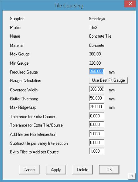
This dialog displays the tile you have selected as well as its coverage data. The maximum and minimum coverage lengths are set when you define the tile.
Required Gauge This is the gauge you want to use when you select the next option as “Use the required gauge”
Gauge calculation This is a toggle between using the gauge you entered, or the process calculating an appropriate gauge.
Coverage width This is the effective width of the tile
Gutter overhang this is the amount you want to have the first course to overhang into the gutter. You can also use this value to effectively offset the location of the second course.
Max ridge gap This is the maximum gap between a ridge and the top of the closest course. That is, a course is not inserted if it falls within this value.
Tolerance for Extra Course The tolerance value alongside the Required Gauge field allows you to set a stretching value. If the depth of the course at the ridge line is greater than the number specified, a course is added to the number of courses up the rafter. The number is expressed as a decimal between 0 and 1. This process is duplicated on all roof planes.
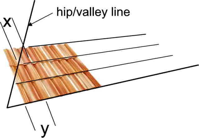
Tolerance for Extra Tile/Course If the width of the tile at the end of a course line (X) is greater than the number specified, a tile is added to that course. The number is expressed as a decimal and usually between 0 and 1 and is effectively calculated as X/Y (Y being the width of a full tile). For example, if the operator specifies a course tolerance of 0.5 on a tile that has an exposure width of 300mm, then for every instance where more than 150mm of course line remains at the end of that course line the software will add a tile to that course. This is duplicated for every course line on the job. A number greater than 1 may be used in special circumstances where the tile panel is very wide, (such as steel tile). A number such as 1.15 will reduce the tile per course by 1.15 pieces, thus allowing for reuse of off-cut pieces.
Add tile per Hip Intersection Adds an extra tile when a course line intersects with a hip intersection. Can be a number less than one. That is, if you specify 0.5, an extra tile is added every other course at a hip.
Subtract tile per valley intersection Subtracts a tile (or part there-of) when a course line intersects with a valley line. That is, if you specify 0.5, a tile is subtracted every other course at a valley.
Extra Tiles to Add per Course Provides to the ability to further refine the quantity calculated to account for other variables such as breakages in transit etc. May be less than a whole number. That is, if you specify 1.5, you will have 1.5 tiles added at the end of every course.
For any of these fields you can enter whatever values you like to obtain the result you desire and these should be verified against field results and experience.
When you click [OK], coursing lines are inserted onto the roof planes. If you had selected counter battens, the lines depicting them would also be inserted.
If you click Delete, the coursing lines on the roof are deleted.
If you click [OK], then the command terminates and the dialog box closes.
For each roof plane, the eave course is laid from the longest eave. From there, an optimum course separation is calculated which will fall between the maximum and minimum values relevant to the tile. Note that the start of the eave course is determined by the gutter overhang.
After the courses are drawn, the number of tiles (excluding any additional ‘waste’ calculations) is reported on the dialog box. You can determine the ‘waste’ when you prepare the quote. Refer to [Set-Up > Set up Pay Rates > Tile waste factors].
The following diagram shows the coursing lines generated on a roof.

Select Shingle
This command lets you select the shingle for the job as well as other shingled roof parameters. When you first select [Select-Shingle], the Select the Shingle dialog box is displayed. Once the required shingle is selected, the current parameters for the selected shingle are displayed.
 ++
++
This dialog reports to you the coverage as well as other geometric values for the selected shingle. Refer to Set-Up > Shingles command to see how you can define and change a shingle definition.
Supplier Supplier’s name as you want it to appear on the reports and material orders,
Profile The name of the shingle profile (if required),
Name If product name is different from Profile,
Material Further means of identifying the shingle.
Colour This drop down box lets you select the colour for this shingle from a list of colours provided by that supplier. Trim shingles which are set to “From field shingle” will also adopt this colour.
Product Code The product code that identifies the shingle. It is wise to use the same code as your supplier so that the orders generated are meanigful to all parties. The Product Code must be unique.
Starter course Clicking this field will open a list of shingles or shakes you can use as the starter course. The starter course is applied to all eaves as well as to rake edges when using shingles.
Starter coverage The line types that the starter product will be applied to – typically eaves and rake, but might be eave only.
Pay rate schedule Clicking in this field will display a list of the pay rate schedules you have defined. Refer to the Set Up > Tile-Pay command to see how you define a pay rate schedule.
Underlay This is the underlay you want to use. It is assumed that you want to apply the underlay to the entire roof. If you want to apply it partially, then refer to the Cover > Underlay command. To define an underlay to appear in this list, you must define a new insulation using Set-Up > Insulation with the name of “Sarking” or “Underlay”. Sarking or Underlay can only be selected by having roof planes with a material applied, be it either metal or tiles. Indeed the digitizing of partial sarking etc. requires these planes to exist and have a material applied.
Shingle Waste File The file that defines the waste factors to be applied to this job. You may define multiple waste files for different products.
Fall protection Here you can define the fall protection you want to use. To get a fall protection item listed, you must define a new user-defined flashing with the Finish set to “Fall Protection”. You do this with the Set-Up > Flashing command.
Fastener The fasteners to be used on the shingle. Fasteners are defined under Set Up > Fasteners.
At the bottom of the dialog, a message is written to inform you which estimation method is used (area or coursing). If you generate coursing lines (see later), the estimation method will become, ‘coursing’.
Coursing Clicking this button lets you perform an estimate by simulating the laying of the tiles course by course. If you do not want to estimate by coursing, you can ignore this step and the estimate will default to the area method ie pieces per square metre (or square).
To cancel the tile selection click [Cancel]
To change the tile selection, click [Change].
To accept the tile selection, click [OK].
This then becomes the cover material for all the tile roof planes in the model.
Default Shingle Estimation Method the estimating method quantifying shingles – the options for estimating shingles are by Area or by Course. Area calculates quantity based on pieces or bundles per square and Coursing actually lays the pieces course by course on the roof model and then counts the pieces. Waste, if defined, is applied later, during the cost reporting operation of Supply Only or Supply and Install. The dialog displays the method you have selected – Area or Coursing.
When you select Coursing, the shingle coursing dialog box is displayed.

This dialog displays the shingle you have selected as well as its coverage data. The maximum and minimum coverage lengths are set when you define the shingle.
Required Gauge This is the gauge you want to use when you select the next option as “Use the required gauge”
Gauge calculation This is a toggle between using the gauge you entered, or the process calculating an appropriate gauge.
Coverage width This is the effective width of the shingle
Gutter overhang this is the amount you want to have the first course to overhang into the gutter. You can also use this value to effectively offset the location of the second course.
Max ridge gap This is the maximum gap between a ridge and the top of the closest course. That is, a course is not inserted if it falls within this value.
Tolerance for Extra Course The tolerance value alongside the Required Gauge field allows you to set a stretching value. If the depth of the course at the ridge line is greater than the number specified, a course is added to the number of courses up the rafter. The number is expressed as a decimal between 0 and 1. This process is duplicated on all roof planes.
Tolerance for Extra Shingle/Course If the width of the shingle at the end of a course line (X) is greater than the number specified, a shingle is added to that course. The number is expressed as a decimal and usually between 0 and 1 and is effectively calculated as X/Y (Y being the width of a full shingle). For example, if the operator specifies a course tolerance of 0.5 on a shingle that has an exposure width of 300mm, then for every instance where more than 150mm of course line remains at the end of that course line the software will add a shingle to that course. This is duplicated for every course line on the job. A number greater than 1 may be used in special circumstances where the shingle piece is very wide. A number such as 1.15 will reduce the shingle per course by 1.15 pieces, thus allowing for reuse of off-cut pieces.
Add shingle per Hip Intersection Adds an extra shingle when a course line intersects with a hip intersection. Can be a number less than one. That is, if you specify 0.5, an extra shingle is added every other course at a hip.
Subtract shingle per valley intersection Subtracts a shingle (or part there-of) when a course line intersects with a valley line. That is, if you specify 0.5, a shingle is subtracted every other course at a valley.
Extra Shingles to Add per Course Provides to the ability to further refine the quantity calculated to account for other variables such as damage in transit etc. May be less than a whole number. That is, if you specify 1.5, you will have 1.5 tiles added at the end of every course.

For any of these fields you can enter whatever values you like to obtain the result you desire and these should be verified against field results and experience.
When you click [OK], coursing lines are inserted onto the roof planes with a representation of the shingle.
If you click Delete, the coursing lines on the roof are deleted.
If you click [OK], then the command terminates and the dialog box closes.
For each roof plane, the eave course is laid from the longest eave. From there, an optimum course separation is calculated which will fall between the maximum and minimum values relevant to the tile. Note that the start of the eave course is determined by the gutter overhang.
After the courses are drawn, the number of tiles (excluding waste) is reported on the dialog box. You can determine the waste when you prepare the quote.
The following diagram shows the coursing lines generated on a roof, with the quantity on each roof plane.

Select Shake
This command lets you select the shake for the job as well as other shake roof parameters. When you first select [Select-Shake], the Select the Shake dialog box is displayed. Once the required shake is selected, the current parameters for the selected shake are displayed.

This dialog reports to you the coverage as well as other geometric values for the selected shake. Refer to Set-Up > Shakes command to see how you can define and change a shake definition.
Supplier Supplier’s name as you want it to appear on the reports and material orders,
Profile The name of the shake profile (if required),
Name If product name is different from Profile,
Material Further means of identifying the shake.
Colour This drop down box lets you select the colour for this shake from a list of colours provided by that supplier. Trim shakes which are set to “From field shake” will also adopt this colour.
Product Code The product code that identifies the shake. It is wise to use the same code as your supplier so that the orders generated are meanigful to all parties. The Product Code must be unique.
Starter course Clicking this field will open a list of shingles or shakes you can use as the starter course. The starter course is applied to all eaves as well as to rake edges when using shakes.
Starter coverage The line types that the starter product will be applied to – typically eaves and rake, but might be eave only.
Pay rate schedule Clicking in this field will display a list of the pay rate schedules you have defined. Refer to the Set Up > Tile-Pay command to see how you define a pay rate schedule.
Underlay This is the underlay you want to use. It is assumed that you want to apply the underlay to the entire roof. If you want to apply it partially, then refer to the Cover > Underlay command. To define an underlay to appear in this list, you must define a new insulation using Set-Up > Insulation with the name of “Sarking” or “Underlay”. Sarking or Underlay can only be selected by having roof planes with a material applied, be it either metal or tiles. Indeed the digitizing of partial sarking etc. requires these planes to exist and have a material applied.
Shingle Waste File The file that defines the waste factors to be applied to this job. You may define multiple waste files for different products.
Fall protection Here you can define the fall protection you want to use. To get a fall protection item listed, you must define a new user-defined flashing with the Finish set to “Fall Protection”. You do this with the Set-Up > Flashing command.
Fastener The fasteners to be used on the shake. Fasteners are defined under Set Up > Fasteners.
At the bottom of the dialog, a message is written to inform you which estimation method is used (area or coursing). If you generate coursing lines (see later), the estimation method will become, ‘coursing’.
Coursing Clicking this button lets you perform an estimate by simulating the laying of the tiles course by course. If you do not want to estimate by coursing, you can ignore this step and the estimate will default to the area method ie pieces per square metre (or square).
To cancel the tile selection click [Cancel]
To change the tile selection, click [Change].
To accept the tile selection, click [OK].
This then becomes the cover material for all the tile roof planes in the model.
Default Shingle Estimation Method the estimating method quantifying shakes – the options for estimating shakes are by Area or by Course. Area calculates quantity based on pieces or bundles per square and Coursing actually lays the pieces course by course on the roof model and then counts the pieces. Waste, if defined, is applied later, during the cost reporting operation of Supply Only or Supply and Install. The dialog displays the method you have selected – Area or Coursing.
When you select Coursing, the shingle coursing dialog box is displayed.

This dialog displays the shake you have selected as well as its coverage data. The maximum and minimum coverage lengths are set when you define the shake.
Required Gauge This is the gauge you want to use when you select the next option as “Use the required gauge”
Gauge calculation This is a toggle between using the gauge you entered, or the process calculating an appropriate gauge.
Coverage width This is the effective width of the shake.
Gutter overhang this is the amount you want to have the first course to overhang into the gutter. You can also use this value to effectively offset the location of the second course.
Max ridge gap This is the maximum gap between a ridge and the top of the closest course. That is, a course is not inserted if it falls within this value.
Tolerance for Extra Course The tolerance value alongside the Required Gauge field allows you to set a stretching value. If the depth of the course at the ridge line is greater than the number specified, a course is added to the number of courses up the rafter. The number is expressed as a decimal between 0 and 1. This process is duplicated on all roof planes.
Tolerance for Extra Shingle/Course If the width of the shake at the end of a course line (X) is greater than the number specified, a shingle is added to that course. The number is expressed as a decimal and usually between 0 and 1 and is effectively calculated as X/Y (Y being the width of a full shake). For example, if the operator specifies a course tolerance of 0.5 on a shake that has an exposure width of 300mm, then for every instance where more than 150mm of course line remains at the end of that course line the software will add a shake to that course. This is duplicated for every course line on the job. A number greater than 1 may be used in special circumstances where the shingle piece is very wide. A number such as 1.15 will reduce the shake per course by 1.15 pieces, thus allowing for reuse of off-cut pieces.
Add shingle per Hip Intersection Adds an extra shake when a course line intersects with a hip intersection. Can be a number less than one. That is, if you specify 0.5, an extra shake is added every other course at a hip.
Subtract shingle per valley intersection Subtracts a shake (or part there-of) when a course line intersects with a valley line. That is, if you specify 0.5, a shake is subtracted every other course at a valley.
Extra Shingles to Add per Course Provides to the ability to further refine the quantity calculated to account for other variables such as damage in transit etc. May be less than a whole number. That is, if you specify 1.5, you will have 1.5 tiles added at the end of every course.

For any of these fields you can enter whatever values you like to obtain the result you desire and these should be verified against field results and experience.
When you click [OK], coursing lines are inserted onto the roof planes with a representation of the shake.
If you click Delete, the coursing lines on the roof are deleted.
If you click [OK], then the command terminates and the dialog box closes.
For each roof plane, the eave course is laid from the longest eave. From there, an optimum course separation is calculated which will fall between the maximum and minimum values relevant to the shake. Note that the start of the eave course is determined by the gutter overhang.
After the courses are drawn, the number of shakes (excluding waste) is reported on the dialog box. You can determine the waste when you prepare the quote.
The following diagram shows the coursing lines generated on a roof, with the quantity on each roof plane.

 Select Metal
This command sets the straight roof material (as well as the curve quality roof material for a bull-nosed verandah).

The selected material becomes the global panel materials for the whole job, unless individual panels or groups of panels are changed – such as when you add polycarbonate roof-lights, or alternating roof panel colours.
![]()
Note: The software is aware that some roof systems, typically residential have relatively simple systems with fixed options for panels and flashing or trim with modest accessory lists. For commercial / industrial metal roof systems they can and usually do become quite complex, especially in the area of edge treatments (assemblies), substrates and predefined accessory systems. Please refer to the Setup Section for detailed instructions for creating these definitions. Precise definition of all parts is ESSENTIAL for the application and automatic parts list generation to work correctly.

In Commercial Mode, you can setup roof substrate and roof system options so that the correct trim is selected for each assembly configuration. This is described in the description of the file format for metal panels. DO NOT use this setup unless you have discussed it with the AppliCad Support Team ahead of trying it.
Also read the details about Commercial Mode and Assemblies in these Help files.
Selection Filters
After clicking Select Metal the dialog box is displayed showing the complete list of defined panels plus a series of ‘filters’ to sort the complete list to those panels that match the sort filter criteria.
For example, if you wish to select from all your defined corrugated profile options, select Corrugated from the Profile drop down list. In the main area, only those corrugated profiles are displayed.

Select from the refined list and then the selected profile is displayed.

If you choose a Finish as Painted, Colour (Color) or Coloured (Colored) material, then a listing of all the pre-defined colours is displayed.
Underlay This is the underlay you want to use. It is assumed that you want to apply the underlay to the entire roof. If you want to apply it partially, then refer to the Cover > Underlay command. To define an underlay to appear in this list, you must define a new insulation using Set-Up > Insulation with the name of “Sarking” or “Underlay”.
Selecting Underlay or Fall Protection at this stage automatically applies the selected underlayment or fall protection to the entire roof area and roof perimeter respectively. If you want to chose where on the roof you want underlay, then select it from the cover menu and select the areas to have underlay applied. Sarking or Underlay can only be selected by having roof planes with a material applied, be it either metal or tiles. Indeed the digitizing of partial sarking etc. requires these planes to exist and have a material applied.
Select Fall Protection from the cover menu and select the edge lines to have it applied.
 Select One Plane
The cover command allows you to assign a different metal roofing material to one or more roof planes.
When you click this command, the Roof cover material dialog box is displayed. Here you should set the new material configuration you want. You will notice that only the straight roofing material is displayed.
After you click [OK], you then select the roof planes you want to adopt this material.
 Select One Panel
This command lets you change the materials used on one or more panels. For your convenience, the panels are highlighted with a hatch pattern to make them easier to select. You can see the result by regenerating the cutting list using Estimate > Tally-Panels.
 Reset Plane
This command resets all roof planes and panels to adopt the material you selected using Cover > Select-Metal.
Metal Colours


After you select the colour you want, the roof cover material dialog box is displayed. The colours are defined under Set-Up > Metal Colours and must be defined first if you wish to use them.
Out of the box, AppliCad provides a bunch of colours that are common in Australia as defined by Bluescope Steel Ltd. You may wish to change these to suit your supplier’s colours. This is done through Set-Up > Metal-colours and is saved in a file called colours.csv. As a text file, the list may also be edited in a spreadsheet program.
The roof cover material dialog displays the material you have selected for the straight roofing as well as the material for the curved roofing (if selected).
To change the selection, click on Change Metal and select the new or different roof cover.
To change the selection, click on Change Metal and select the new roof cover. Select Accessories to review the available accessories for the selected panel.Sheet/Panel Accessories
The Accessories button lists all the accessories that have been defined that are associated with the selected panel. These items are saved to a file called sheetaccessories.csv.

Additional items, unique to this job may be added to this list at this time and are saved with the job data. These are NOT added to the predefined list of sheet accessories. Sheet accessories would normally include clips, screws, seam tape, underlay etc.
Pay rate schedule This field defines the pay rate schedule you want to use to estimate the labour cost. The schedule is defined under Set-Up > Set up Pay Rates > Metal-Pay. If you have not defined any schedules, then you do not actually see this particular field. If you select “Use Metal-rates” then the labour will be calculated using the Reporting > Metal-rates values. (This was the default method prior to version 3.2).
Allowances This option allows you to use the Default allowances or to select an allowance set that is specific to the profile of sheet or panel that you have selected. (The allowances are defined under the Estimate menu and would typically be saved to a name that relates to the profile in use).
When you click [OK], those settings are saved as the global cover materials for this job. The roof cover material you have set applies to all roof planes in the current job.
Flashings
This command allows you to set the flashing you want for each of ridge, valley, fascia, gutter, barge (aka rake), apron (aka end-wall or roof2wall), box gutter and step flashing (aka side-wall). These become the global settings for each of the flashing line category types. You can select predefined flashing or define custom flashings. The actual names you wish to use to define the line types can be defined under Set-Up > Preference Settings > System Preferences > Line Styles.
After you select Flashing, the roof flashing and trim material dialog box is displayed.
(If no flashing lines have been defined (typically when no job is present) then you get a virtually blank dialog.)

As the model is created and as line types are added to the model during construction of the roof model, the list is populated with line categories (as shown below). Each line category has a drop down list of all predefined flashing that match that line category.
![]()
Note: The software is aware that some roof systems, typically residential have relatively simple systems with fixed options for panels and flashing or trim with modest accessory lists. For commercial / industrial metal roof systems they can and usually do become quite complex, especially in the area of edge treatments (assemblies), substrates and predefined accessory systems. More detailed instructions for creating these definitions are below, and include Assemblies. Precise definition of all material parts is ESSENTIAL for the application and automatic parts list generation to work correctly.

Select the required flashing for each line catergory by double clicking in the cell for each item. The drop down box displays all available options. At this stage the accessories for each item can be checked if necessary. The accessories are as defined during the Set Up > Flashings.
The standard accessories will be calculated as previous defined during set up. However, it is possible to add or subtract accessory items at this late stage by simply double clicking the accessories cell next to the flashing that needs changing. The standard accessories list will be displayed.

However, if for any reason at all certain accessories are not required to be estimated for this job only, you can select the [X] button and delete that item for this job.

However, if you have deleted the wrong items or decide to put them back into the quotation, you select the [Reset] button, and the standard items are returned to the quotation.

As the example below shows, all your pre-defined flashing options are displayed that match the line category – None (no trim is applied to the line); Custom (custom fabricated trim parts) and Assembly (for aggregated or groups of flashing materials that make up an edge treatment such as a box gutter or parapet cap); or a bought in regular flashing item usually fabricated in a roll-former.
All these materials must first be defined using Set-Up > Flashing.

Installer Pay Rate
At the top of the box, is the option to select the required Install Pay Schedule for Supply and Install jobs. This rate is defined under Set Up > Metal Pay Rates. You can have a FIXED rate (just one rate for all different pitches) or a VARIABLE rate (different rates for pitch and storey). You may define several Metal-Rate files but remember the overhead of keeping them up to date and current. Only define as many rates as you need for the way your crews work. Refer to that section of the manual for how to define your pay rates.
A special rate for any flashing item that has extra processes that changes the cost compared with regular trim, say scribing hip caps or caulking ridge Z bars, may be set up and when the flashing item is selected (with that pay rate defined under Setup – Pay Rate Schedule) that special or alternat rate will be used instead of the regular rate for this category of flashing.
Allowances
Adjacent to Pay Schedule, is the option for Allowances in Use. This displays the allowance file in use. The drop down box allows you to select from all the allowance files you have defined. You set up the allowances using the dialog that opens by selecting the Allowances button at the bottom left of the page. You may have many different allowances for various roof systems. See below for details.
The flashing material colour defaults to the colour of the roof material. If you need a different colour, remember to change it.
![]() Note: Whenever you generate a cutting list/material list all the details are saved with the model. This is to ensure that when you next go into the model sometime later, the details (quantities and costs) are saved and will be stored as originally calculated. These are the quotation details as they were when you originally quoted the job.
Note: Whenever you generate a cutting list/material list all the details are saved with the model. This is to ensure that when you next go into the model sometime later, the details (quantities and costs) are saved and will be stored as originally calculated. These are the quotation details as they were when you originally quoted the job.
If the flashing definitions (including updated priccing) have been changed since the last quotation, when you next go into that job, the user is prompted to update the details so that a new quotation can be produced, with the latest pricing definitions. A dialog is presented reminding you that this is an option:

Be aware that if you select [Yes] this will change all the old details to the new details and new pricing so that the job can be re-calculated with the current pricing.
It would be advisable to then save the model as a new job so you have both the old job costing and the new job costing details.
Selecting Roof Batten/Purlin
The operator has the option of selecting the main roof batten plus a secondary or intermediate batten where the building code requires such a device – usually as a fall barrier for installers.
Selecting the Batten or Batten2 buttons brings up the list of batten/purlin materials available for that line style. In this example we have quite a few batten material options.

The roof batten button Batten has an Insert/Modify option. Selecting this button opens up the dialog box shown below and allows for comprehensive set up of your roof battens/purlins. Battens/purlins may be inserted and quantified on metal or tile roof categories. The tile roof category is primarily for those roofers installing metal tiles such as Metro or Gerard. Clay and concrete tilers typically build the cost of their timber battens into an all inclusive price.
Once selected, the following dialog box is displayed showing the options for inserting the battens/purlins.
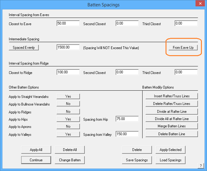
The operator can define the batten spacing and the program provides for the spacing to use near the top and bottom and left and right of the roof plane to suit the requirements of certain building codes, especially in cyclonic or hurricane prone areas.
The intermediate batten spacing may also be set. The options for the intermediate spacing, that is the batten spacing after the pre-set batten spacing, may be a fixed spacing of the specified amount or spaced evenly along the length of the roof plane up to the maximum spacing. Note ability to space battens/purlins from top (ridge line) down, rather than the bottom (eave) up.
Other Batten Options
Apply to straight verandahs This is a toggle to determine if you want battens drawn on straight verandahs in this job.
Apply to straight verandahs This is a toggle to determine if you want battens drawn on bullnose verandahs in this job.
Apply to Ridges Applies battens along the ridge line on each roof plane with a ridge line at the spacing from the ridge that you specify.
Apply to Hips Applies battens along the hip line on each roof plane with a hip line at the spacing from the hip that you specify.
Apply to Aprons Applies batten to apron lines.
Apply to Valleys Applies batten to valley lines.
Many batten/purlin configurations require the battens/purlins to be split at a roof frame member – a rafter or a truss. This may be the case for a typical portal frame commercial structure. If the battens/purlins need to be split, use the Divide at Rafter Line option then the operator needs to indicate at which frame member the batten/purlins will be divided.
Individual battens/purlins can be divided or all the battens/purlins on the roof plane using the Divide All at Rafter Line.
If a line is not on the drawing where you need a batten/purlin divided, then you have two options to insert a line to use as a reference line to divide the batten/purlin. Insert Rafter/Truss Line option prompts for a line parallel to the required rafter line. An adjacent eave line will usually do it. Then you are prompted for the spacing or offset from the reference line to the location of the required rafter line.
The Delete All Rafter/Truss Lines option deletes these lines once the operator is complete and they are not necessarily required to be displayed on the drawing.
If a batten/purlin is incorrectly divided, then use the Merge Batten Line button. The Delete Batten Line completely removes the Batten/Purlin from the model.
Apply All Applies battens/purlins using the spacing definitions set.
Delete All Deletes all batten/purlins from the model.
Delete Deletes the battens as selected.
Apply Selected Applies battens to a wall using the current settings. Use this to modify batten spacing on a wall by wall basis.
[Continue] Takes the operator back to the Flashing dialog to continue setting up roof trim.
Change Batten Changes to a different batten material.
Save Spacings Saves the current settings. Use this to set up different spacing settings for various roof systems.
Load Spacings Read into the current job, spacing settings from a predefined set.
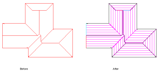
The battens are drawn on the model according to your specification. Select [Continue] and you will be returned to the Select/Generate Roof Batten/Trim dialog box.
![]()
Note: This process may be used to design and estimate a retro-fit batten system such as RoofHugger™. This is described in detail in the Appendix.
Selecting a Flashing
The select flashing (trim) option displays a dialog as shown below. Only line-type options that exist in the model are displayed. That is, if a box gutter line type does not exist in the model, then that row of option is not displayed. This keeps the selection process simple to manage. If you subsequently add a line type, then that row will be displayed and you must go back and assign a trim profile to it.
To select a new flashing for a particular line type, click the relevant flashing cell (Ridge, Valley, Fascia etc) and the available definitions for that category are displayed.

Here you can:
Select None and have no flashing on this line type.
Select Custom, and have a custom profile on this line type. A Custom flashing is typically a flashing fabricated in a press break to particular specifications.
Select Assembly so that an assembly of flashings, defined previously as either a regular flashing or a custom flashing, will be attached to this line type. If the assembly has a graphic figure associated with it, then you are prompted to insert it on the drawing. The assembly is still selected even if you cancel the insertion of the figure. The figure is ignored when you print the automatic reports and drawings. However, you can compose your own plot using the Plot command. (See Set-Up > Flashing-Details to create an assembly.)
The placement of an Assembly Detail (whether it has been created or otherwise) [Add Assembly Detail] button at the bottom of the Cover > Flashings dialog allows the user to insert an Assembly Detail image whether the assembly has been specified or not. Such details can be used to provide additional and sometimes essential extra information for the installers. For example, here we have a reference to a special Ridge Assembly by type and a reference to an apron flashing or wall corner (whatever you need).

Select a regular flashing material. These regular flashing profiles are usually fabricated in a roll-former and cut to length. These materials are defined by the Set-Up > Flashing command.
Refer to the relevant section in this manual – Set-Up > Flashing, Set-Up > Flashing-Assemblies and Set-Up > Custom Profile – for more information on how these are all defined.
If the flashing you selected defined as Colour, Color, Coloured, Colored or painted, then you are prompted to select a colour from the Metal Colour list too. Metal colours are defined under Set-Up > Metal Colours.
Barge/Rake flashing on Gable Ends
Barge/Rake lines are drawn as sloping lines after you have modified the outline to tell the software that these lines are “barges” or you select the eave line to be a vertical plane (gable). As a result, when the lines are drawn and the model is created, the lines become “GABLE” lines.
Other linetypes that might be used on a ‘gable end’ are FASCIA-BARGE , FASCIA-ONLY and BARGE-ONLY, but the operator must manually select each line to change it to one of these options.
Any fascia flashing defined as part of a job is applied to an eave line (FASCIA) as FASCIA, but to a GABLE line as FASCIA-BARGE. It may be the same flashing product, but it appears as a different item in the flashing cutting list. FASCIA-BARGE in most instances just highlights that it’s a fascia flashing, being applied to a barge or gable end. This becomes an important distinction if you have defined accessory items such as ‘barge-mitres’ ‘rake-corners’ etc that are only applied if the fascia line slopes up or down.
So if you want to apply Fascia AND Barge flashing to your gable ends, then you need to ensure that you have a Trim type selected for both the Flashing category and the Gable category.

Selecting a Custom Flashing
You select a custom flashing by selecting Custom from the flashing list. After you select Custom, the Define a custom flashing dialog box is displayed.
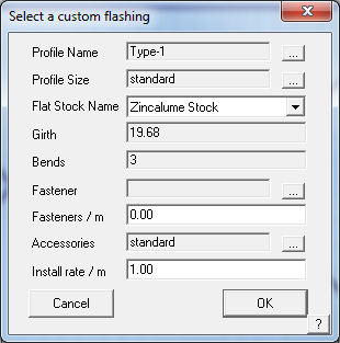
Name This is the name of the Flat Stock Sheet table you defined under Set-Up > Flat Sheet. This table defines the fabrication cost given a matrix of girths and bends. It also defines the stock sheet size and material and finish.
Girth This is a drop down box of girths defined in the relevant table
Bends This is a drop down box of bends defined in the relevant table
Fastener This is the fastener you want to use for this flashing. To select a flashing, click the button on the right hand side.
Fasteners/m This is the number of fasteners you want per unit length
Profile name This is the name of the actual profile to be used. This list is derived from profiles you created from Set-Up > Custom-Profile. If you select a profile you will be able to verify the profile graphically as well as produce custom flashing reports.
Accessories This displays the list of accessories for the profile. If you had filled out the accessories using the Set-Up > Custom-Profile > Accessories command, you can then see them here. You can also change them if you wish. If you do not change the list, the word “standard” is displayed. If you have changed the list, the words “non-standard” are displayed.
Install rate/m This is the where you set the labour rate for the custom flashing
When you select the profile selection box, the following dialog box is displayed.
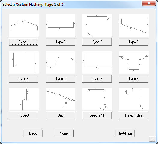
This dialog displays for you a selection of those profiles you have created. To select the one you want, click on the button beneath the graphic.
When you select a profile, the Define Profile Dimensions dialog is displayed.
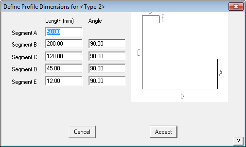
Here you either accept the default values (the values used when you drew the profile) or change the dimensions and angles to suit this particular job. You can also change them if you wish. If you do not change the list, the word “standard” is displayed. If you have changed the list, the words “non-standard” are displayed in the Profile size field.
When you click Accept, the definition is saved and the Custom Profile dialog is redisplayed.
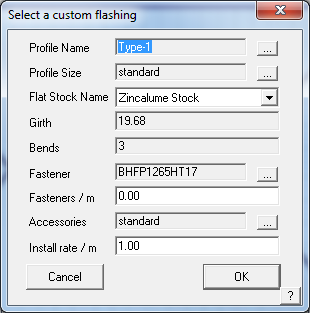
Now you see:
the profile name you selected
the profile size. The size is either “Standard” if you did not change the default dimensions,
name of the flat stock sheet from which the custom profile is fabricated
the girth and bends of the profile
the fastener you want to use
and the installation rate for the labour.
When you click [OK], you are returned to the Roof Flashing Material dialog and that material is listed against the line type.
Flashing Allowances

To set the flashing allowances, click the Allowances button.
Here you can set the standard allowances you want to add to each flashing type and sheet. After you select this command, the Flashing Allowances dialog box is displayed.
Metric or imperial units must be used in accordance with whatever you have set as your system units of measure.
Metric is displayed here.
Run Allowance This is the amount added to each run regardless of the length of the run. You can treat this value as an end allowance.
Lap Allowance This is the amount you want to add to take piece overlap into account
Internal Corner allowance This is the amount you want to add to a gutter or fascia run if there is an internal corner at an end.
External Corner allowance This is the amount you want to add to a gutter or fascia run if there is an external corner at an end.
Combine Similar Length Flashings After you generate a flashing list, lengths which are less than this amount apart, are assumed to be the same length and are merged together. The shorter lengths are merged into the longer lengths. This helps the installers by not having too many different lengths in the pack and overcoming the portential of cutting the longer back only to leave a shorter one that is now not suited to the task.
Minimum Run Length This is the minimum run length which will be treated as an independent run. Runs less than this length will be added to an attached run.
Round-off Flashings to Next This can be defined as any number, it will then round up to that number.
Flashing Annotation – Text Size This sets the text size on the flashing report that is printed. It is millimeters. If you work in Feet/Inches, it still uses millimeters. 2.5mm is pretty close to 1/8”.
Single-Allow
Clicking this button lets you set a user defined allowance to a particular run. For example, you may want to add extra allowances for valleys around dormers.
After you click Single-Allow, you enter the allowance you want to add, then select the line you want to add the allowance to. When the flashings for this run are quantified, the run length will then become the actual length of the line plus the allowance.
Allowance Sets
Load
This button allows the operator to load a previously saved flashing allowance file.
Delete
This button deletes an allowance file.
Save-As
This button allows the operator to save an allowance file that suits a particular roofing system. You may have as many different allowance files as you need.
When you click [Cancel] the flashing dialog box is displayed and changes you made to the allowances are discarded.
When you click [OK], the flashing dialog box is displayed and changes you made to the allowances are retained. If you have created an allowance file, you will see [OK]/Update which gives you the option to change the currently displayed allowance file.
![]()
Note: Be aware that the DEFAULT allowance settings are not saved as an external file but within the Roof Wizard. If you change the settigs and select [OK], they become your new default settings. You can change the settings and select Save-As and define a new name such as ‘Corrugated762’ and these will be saved to a file called Corrugated762.AL2. They will then appear in the list of saved trim system allowance settings for flashings and trim, all with the *.AL2 file extension.
If a special or pre-defined allowance file is in use for the current job, the name of that file, is displayed in the cell [Allowances in Use].
Generate
This command generates a flashing cutting list for this job depending on the estimation you have set for each flashing type. If you have selected an estimation method which deals with each run individually, the cutting list for that run is automatically annotated on the drawing. If you have selected a batten, but not inserted them, then you are prompted to do so.
When you click this command, the flashing list is displayed on the Flashing cutting list summary dialog box. All flashing and trim items are listed and below that are all thr flashing and trim accessory items.
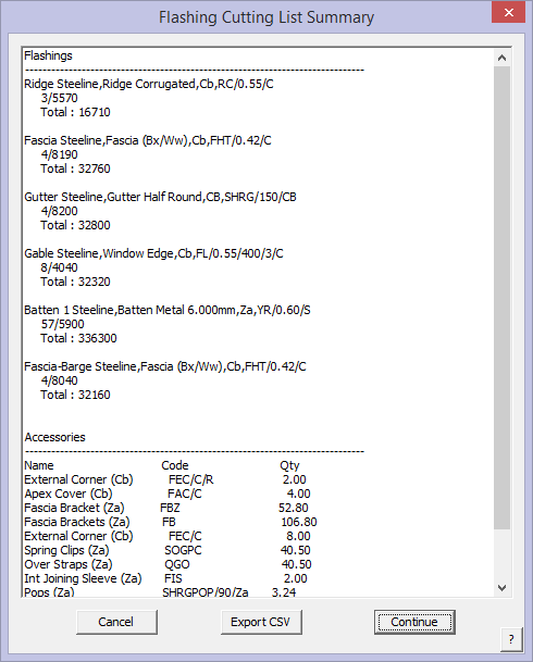
Here you see the cutting list for each flashing type, as well as the number of flat sheets for the custom flashing. The Accessories button brings up the list of all accessory items required to complete this installation.
If you want to export this flashing list to a comma separated value file (.csv file), a text file that can be read by a text editor for import into another system, click ExportCSV. To see the accessories quantified for all the flashings in the list including stop ends, gutter clips and rafter brackets etc, click the “Accessories” button.
![]()
Remember: To accurately report the flashings in the Reporting summary, you must ‘Generate’ the flashings first. If you change any flashing type, you must re-Generate the flashing list.
Click [Continue] to return to the flashing dialog box.
The following diagram shows the cutting list displayed on the roof model.
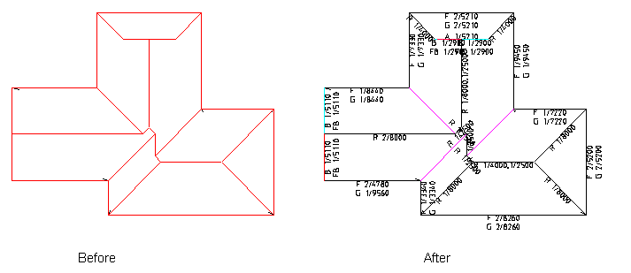
Flashing Fabrication Angle
An option exists to also display the angle of bend for fabrication of certain trim pieces, especially hips, valleys and ridges. This option is set when you define the colour, style and weight of your flashing lines. To turn on, simply double click the cell next to the flashing type, under the Show Angle column.

When set, indicated by the [X] in the cell, the cutting list and all subsequent reports include the bend angle as show below.

More details here.
Flashing Sets
Load
This command loads the flashing types previously saved as a “system”.
Save-As
This command sets the currently selected flashing types to be saved as a “system” for future use. A naming convention that identifies the “system” such as ‘SSR Trim’ or ‘CorruTrim’ would work. This is then available for immediate selection when required using [Load].
Delete
Deletes a predefined Flashing system.
Other Flashing Options
Colour Set
To quickly set the colour for each of the Coloured flashings, click Set Colour. Then select the colour you want.
Single-Line
This command lets you assign one or more extra or different flashings to a line you select. When you click this button, you are prompted to select a line. This is the line to which you will be adding or changing the list of flashings. After selecting the line, the following dialog box is displayed.

This dialog box shows you the line type for the line (in this case it is a FASCIA). You can also ask the system to report the base flashing for the line as well, or not, by clicking the ‘Do report’ button which toggles from ‘Do report’ to ‘Do not report’.
If there are no single flashings attached to the line, you are informed that ‘There are no single flashings associated with this line’.
To attach a flashing to the line, click Add-Flashing. Single Line flashings may also be inserted along arcs. The list of flashings is then displayed, from which you select one. After you have selected a few flashings, the dialog box would look like the following.

In this example, 3 flashings have been selected. For painted flashings, you are also prompted to select a colour for the flashing. To the right of each flashing are three buttons allowing you to delete the flashing, change the flashing or add a new flashing to the one you have selected. These are the buttons labelled [-], […] and [+].
When you select [OK], you get the opportunity to continue selecting other lines that might have the same unique treatment on them. Right mouse click to ‘cancel’ and quit changing the lines. Quite complex trim systems can be made using this technique – for example vented ridges. All the required accessory items as have been defined for each trim/flashing item are also quanitifed automatically, based on the definitions.
User-Lens
This command allows you to add user defined flashing items to lines in the model. First, the Select a flashing dialog is displayed. This list will display only those flashings defined as User defined. Then you select the line or lines you want to apply this flashing to.
Chg. LineType
Allows the operator to change the line from say, ‘Gutter’ to ‘Fascia and Gutter’, without having to exit the Flashing dialog.
Define Flashing
This button takes you straight to the Set Up > Flashing dialog so you can define or modify a flashing. This saves you having to exit and go to Set Up.
Set All to None
This allows you reset all the selected flashing definitions to none so you can set new flashings for the current job.
Move Text
This function allows Flashing Annotation text to be moved and this location will be remembered when the flashing is re-generated into the future. Previously, any moved text had its position reset by the software and this could result in a large amount of text manipulation being lost if the user encountered any errors with the flashing annotation such that it required a re-generation.
View Options
Show
Shows the Description of the Flashing selected on each line. It might get a bit busy, so don’t hesitate to zoom in and scroll around to check all the lines. A repaint by scrolling in or out will remove the annotations.
View List
This function allows the user to review the generated cutting list, without having to re-generate.
Setting the pay schedule
For Roof Wizard and Roof Wizard the pay schedule is set under Cover > Select-Metal and defined under Set Up > Metal-Pay. For Roof Wizard and Roof Maestro, the metal pay schedule is selected on this dialog box by selecting an option from the pay schedule dialog box. If there are no schedules to choose from, then you must define some using Set Up > Metal-pay.
The currently selected pay rate schedule in use is displayed in the cell [Installer Pay Rate].
Close the dialog box by clicking [OK].
 Select Membrane
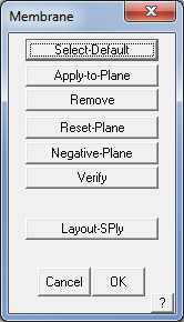
This command allows you to create groups or layers of individual membranes (as a roof system) to the entire roof or simply to parts of the roof. You can even assign areas which have no system applied. When you click this command, a sub-menu is displayed.
Select-default
This option allows you to set the system for the entire roof. When you first click this command, the Membrane list states there are no membranes selected in your roof system.

Consider a membrane as a layer in your roof system. A membrane does not have to literally be a membrane, it can also include base ply, asphalt, interplay, ballast etc – all the layers that make up your roof system. Note that asphalt may be defined as a fastener because it can be considered a type of adhesive material that is supplied as bulk liquid. Refer back to Set-Up > Membrane for how these products may be defined.
When you click Add-membrane, the list of available membranes is displayed. You do this for each of the membranes you want. When you click Add-Fastener, the list of fasteners is displayed. You then enter the application rate for this fastener. The membranes and fasteners are displayed separately in the dialog. The order is not relevant for the estimate, but it helps to have them in some sort of order, say the order of application, so that you can more easily see that it is correct when you select it for use on a different job.
You can select up to 20 different membranes to create a ‘roof system’. This may be saved as a system for later use.
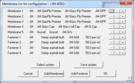
When you click Select system, a list of roof systems is displayed from which you can select one. After you do select one, the list of materials associated with this system is displayed.
The manipulation buttons to the right of each line item are:
– Delete this line
… Change this line
+ insert an item before this line
When you click [OK], the list of membranes you have selected is applied to all Low-Slope roof planes in the job.
Apply-to-Plane
This command allows you to apply the system to a single plane, independent of the global settings. You first select all the planes you want to change, then build the list of membranes you want. Those membrane settings are then stored with that plane.
Remove
This option allows you to have no system applied to the selected plane. First you select one or more planes. When you accept the selection, those planes will be marked as having no membrane.
Reset-Plane
This command allows you to reset all the planes in the job to adopt the global membrane list. That is, it removes any user defined changes you have made.
Negative-plane
Here you can insert a negative membrane area. After you digitise points defining the extent of the area, a plane is inserted. When the total amount of membrane is tallied later on, this area will be subtracted from the plane area to leave a nett membrane area. You can select the type of membrane for this negative area the same way you do for a standard plane.
Verify
This command displays in a dialog box, the membrane associated with a plane you select. It also notes if the plane is actually a negative area.
Layout-SPly
This command lays out single-ply membrane on a low-slope roof allowing for different perimeter and field sheets and fasteners.
When you select the command, you first select the roof plane you want to cover, then the membrane supplier you want to use. After selecting the membrane to use, the Single-Ply layout defaults dialog box is displayed.
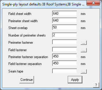
Field sheet width The width of the field sheets
Perimeter sheet width The width of the perimeter sheets
Sheet overlap The width of the lap between perimeter sheets
Number of perimeter sheets The number of perimeter sheets you want to use
Perimeter fastener The fastener you want to use for the perimeter sheets
Perimeter fastener separation The fastener spacing for the perimeter sheets
Field fastener separation The fastener spacing for the field sheets.
Seam tape The seam tape to use on all longitudinal and end seams. You must have defined the seam tape as a roll type fastener using Set-Up > Fastener.
You would use Set-Up > Membrane to define the sheet widths.
When you click Apply, you will notice that the perimeter sheets are then constructed around the perimeter of the roof plane. You are then prompted to select a line which defines the direction of the field sheets. The field sheets will be laid parallel to the line you select. Then you need to locate a position through which a seam will occur.
After the field sheets are constructed, a material report is displayed detailing the number of perimeter and field sheets, as well as the number of fasteners.
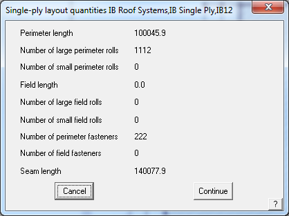
Click [Continue] to finish the process.
The following diagram shows a single ply layout including perimeter sheets and field sheets.
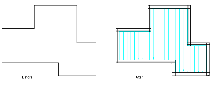
Delete-SPly
Deletes all single ply membranes applied to the roof model.
Select Insulation
 This command allows you to assign various insulation and underlay (or sarking) materials to the entire roof or simply to parts of the roof – as an individual item such as foil or as a ‘system’ which might comprise asphalt, board, membrane etc. You can even assign areas which have no insulation and areas that may have an alternate insulation. When you click this command, a sub-menu is displayed.
Select-Default
This option allows you to set the insulation and underlay (or sarking) for the entire roof. When you first click this command, the Insulation list states there is no insulation selected.
When you click Add-Insul, the list of insulation types is displayed. You do this for each of the insulation systems that you want.
You can select up to 20 different insulation materials to make an insulation ‘system’ and they can be saved for re-use later. To remove the default insulation materials, click Remove. This resets the list to being empty.
After you have selected two insulation materials to create a system, the list would look similar to that below. When you click [OK], the list you have selected applies to all planes in the job.

Apply-to-Plane
This command allows you to apply the defined insulation system to a single plane, independent of the default settings. You first select all the planes you want to change, then build the list of insulation coverings you want. The new insulation settings are then stored with the selected plane(s).
Remove
This option allows you to have no insulation applied to the selected plane. First you select one or more planes. When you accept the selection, those planes will be marked as having no insulation.
Reset-Plane
This command removes any alternate systems you have selected and resets all the planes in the job to adopt the default insulation system.
Negative-plane
Here you can insert a negative insulation area. After you digitise points defining the extent of the area, a plane is inserted. When the total amount of insulation is tallied later on, this area will be subtracted from the plane area to leave a nett insulation area.
Verify
This command displays in a dialog box, the insulation associated with a plane you select. It also notes if the plane is actually a negative area.
Show
This highlights for you those roof planes to which you have applied some insulation.
 Select Downpipes
This command displays a submenu which allows you to select and draw downpipes.

A downpipe is simply a 2D dot drawn on the line you select. When all the materials for the job are tallied later on, each downpipe will spawn lengths of pipe, a pop, offsets, and possibly an elbow or a shoe.
When you first click this command, the list of available downpipes is listed. This selection then becomes the type of downpipe for all the downpipes in the model. You can mask the display of downpipes with the Utilities Set-Display command.
Select
This command allows you to change the type of downpipe you want for this job.

Insert
This command allows you to draw a downpipe.
After you click Insert, you are prompted to locate a line onto which the downpipe is inserted. Typically, you would select an eave line. A downpipe is drawn on the line you select.
Then the Downpipe values dialog box is displayed. This dialog allows you to set parameters for the downpipe. The software will allow up to 20 different downpipes to be inserted on the one job.
Height of gutter This is the height of the gutter. The default value is the height of the gutter above zero. You would enter a suitable value here so the Reporting section can resolve the number of fixed length pieces of downpipe required for this job.
Offset to wall This is the offset distance to the wall so the system can determine the type of offset piece to use. The default value is the horizontal distance to the closest wall. If it is zero, a wall was not found close by.
Base of downpipe This is a drop down list where you can assign the base piece of the downpipe to be nothing, an elbow or a shoe.
Dot Size Allows the operator to define the size of the dot that represents the location of the downpipe, making them easier to see on the drawing. Size is in millimetres. Shown below is a 2mm dot and 5mm dot.

After you click [OK], the downpipe is inserted.
Here you can see the downpipes drawn as solid dots.

Change
Here, you can change an existing downpipe. After you select the downpipe in the model, the Downpipe values dialog box is displayed. The values in the dialog box are those you first inserted the downpipe with. After you make the changes, click [OK] to make them permanent.
Delete
This command allows you to delete downpipes in the model. After you click Delete you then select the downpipes to delete.
Show
This command annotates alongside each downpipe in the model the supplier, size, finish and colour. A repaint will remove this text.
Tally
This tally’s downpipes and accessories, thus confirming that you have everything you need before you go to the Reporting stage.

 Select Underlay
The underlay command lets you apply and remove underlayment from the roof. The icon command uses the ‘S’ character because it was originally entitled “Sarking”. Underlay is a moisture barrier material also referred to as ‘sarking’ in many markets, ‘foil’ or just as ‘moister barrier’ in other places. If the roof underlay requires more than a single layer of material, use the Cover > Insulation option.
When you selected a cover material for your job using Cover > <Metal, Tile etc>, you may have selected an underlay material as an option. At that stage, it is assumed that you want to cover the entire roof and the software goes ahead and does just that. Using the Cover > Underlay option you can stipulate exactly where you want underlay if you want the job to be only partially covered. To adjust the underlayment in this way, the type of underlay material must have been selected with your primary roof cover material first. Once you apply underlay to some part of the roof, you must define all the areas you want it to apply to.
To be able to select the underlay material, it must be defined under Set-Up > Insulation and the product Name must be Sarking or Underlay. This curiosity in regards to underlay (which is an insulation product) is to satisfy roofers in certain markets where the colloquial term is sarking or underlay.
Apply-Partial
This command lets you select one or more roof planes to apply underlay to. By definition, those planes you do not select will not have underlay. By doing so, you have defined the roof as having partial underlay rather than fully underlaid.
Remove-Partial
This command lets you remove the underlay tag from a roof plane you previously applied underlay to. If you remove underlay tags from all the roof planes then it is as though you want to remove all partial underlay, and return to a fully underlaid roof. (To have underlay on the roof you must set the Underlay on the Cover > Select-Tile or Select-Metal dialogs to be something other than ‘None’).
Remove-Partial-All
This command removes the underlay tag from all roof planes in the job. In effect returning the roof to a fully underlaid roof. (To have underlay on the roof you must set the Underlay on the Cover > Select-Tile or Select-Metal dialogs to be something other than ‘None’).
Show
This command will block fill the area where underlay is applied.
Dig-Part

This command lets you digitise a shape in which you want partial underlay to be applied. Now you can have underlay partially applied on a roof plane. The method used to digitise this shape is similar to the Construct Roof > Dig-Outline command or the Modify Roof > Cut-out command.
Underlay Allowances
Sets allowances for additional underlay to cover hips and valleys.
 Fall Protection
The fall protection option allows custom application of fall barriers to the perimeter of the roof or indeed any other lines. Fall Protection must first be defined with the Set-Up > Flashing command, with the Finish set to “Fall Protection”.
To apply the fall protection, it must be selected in either the Cover > Select-Tile and Cover > Select-Metal commands. Here you can nominate which additional lines will have fall protection and which lines where it may not be required.
To auto-select it for a job go into the metal or tile selection box and click on the arrow at the end of the Fall Protection field. A drop down box will appear and the fall protection that you just created will be there. Select it, and you will have fall protection added to your job on all eaves that are above the FP Height set at that time.

For example with metal roofing panels selected, the following dialog box shows the panel and the critical setting is seen – FP Height.
 If you select a Fall Protection item here, and then set the FP Height (height of any perimeter line above the construction plane (CPL), then the selected Fall protection Item is added to all edges.
If you need greater discretion or a variety of fall protection items applied to the roof model, because of building codes or practicality, then you should not select it here but under Cover > Fall Protection. This provides for you to first of all select any fall protection type to any line in the model and have multiple types of fall protection items on the job.
You may select up to three different fall protection items in a single job – for example, side netting, two rail fence and 3 plank scaffold – and these must be added one at a time, selecting each line that each is applied to when prompted.

Apply
This command lets you apply fall protection to all lines that you select. Once you select a fall protection you then select all the lines you want it applied to. Select it, and you will have fall protection added to your job on all eaves that are above the FP Height set at that time.
Remove
This command lets you select lines to which fall protection has been applied, and removes it.
Show
This command will highlight all lines that have fall protection material applied to them.
 Fixtures
This command displays the list of fixtures you have already defined with the Set-Up > Fixtures command. Depending on the insertion method for the selected fixture, you are prompted to select a single point, 2 points or a line. When you have done that, the graphic figure of the fixture is inserted.
Selecting the command, brings up a Thumbnail preview with the name of each Fixture.

If you selected to have the fixture cut a hole in the roof plane, the roof plane (and hence the roof material) is removed from under the fixture.
When the fixture is inserted on the roof, the fixture layer is modified based on the storey of the roof that they are installed on. For example – A fixture installed on a single storey roof will therefore be on Layer 11, with a second storey fixture on Layer 21. This ensures fixtures turn on and off with their respective storey.
To generate the flashing and trim cutting list for these fixtures, along with the trim package for the rest of the roof, you must perform the Cover Flashing Generate command. The flashings derived from these fixtures are then accumulated with the other flashings in the job.
The quantity of fixtures is automatically tallied when you perform a costing. Refer to Set-Up > Fixtures to see how you define a fixture.
Fixture Array
This command performs much the same functionality as described for Cover > Fixtures, however it adds the opportunity to then copy the fixture just inserted a number of times in both the X and Y coordinates, thus creating an array of fixtures. This function is especially useful for arrays of skylights or photovoltaic panels and saves the user from having to insert the same fixture a number of times over and over.
Firstly, a list of fixtures is displayed that you have already defined with the Set-Up > Fixtures command. Depending on the insertion method for the selected fixture, you are prompted to select a single point, 2 points or a line. When you have done that, the graphic figure of the fixture is inserted.
If you selected to have the fixture cut a hole in the roof plane, the roof plane (and hence the roof material) is removed from under the fixture.

Once the fixture is inserted, the Copy Array dialog then appears, asking the user for the number of copies to produce in both the X (left/right) and Y (up/down) axes. Entering the Number of copies and the distance in each direction for each copy creates an array of these fixtures, copying all elements of the fixture including the hole in the roof plane (if it exists).

To generate the flashings list from these fixtures you must perform the Cover Flashing Generate command. The flashings derived from these fixtures are then accumulated with the other flashings in the job.
The quantity of fixtures is automatically tallied when you perform a costing. Refer to Set-Up > Fixtures to see how you define a fixture.
 Flashing Assemblies
This command allows you to set up roof flashing assembly details. These definitions comprise one or more flashings as well as a flashing detail graphic. Each flashing item used in an assembly must exist already as a standard profile flashing or a custom flashing profile material as described above.

Name of Assembly Group – Group name, refer below for more details.
Name of flashing Assembly This is the name you define for this flashing detail. You will use this name later when selecting flashing or edge assembly details.
Modify/New to add or change the details of an assembly.
Database name of graphic detail This is the name of the database (*.dab file) containing the subfigure of the graphic detail (the next field). When you click this field, you can select the database you want. The default database name is EdgeAssembly.dab.
Figure name of graphic detail This is the name of the CAD subfigure to be inserted when you select this flashing assembly or detail. When you click this field, the list of PDF’s and CAD subfigures in the given database name are listed. From this list, you select the one you want.
Add Blank allows you to simply insert a product code for an item and the details can be extracted from the existing definition of the profile from the Falshings_V6.csv file – substantially improving data entry speed.
Add-Flashing This allows you to add a flashing to the list of flashings which define this edge assembly.
Add-Accessory This allows you to add ab accessory item to the list.
Add-fastener This allows you to add a fastener to the list.
Modify/New This allows you to select an existing flashing assembly definition or add a new flashing assembly definition.
When you click [OK], the details are stored in the binary data file called – EdgeAss.csv.
Material data files such as this are best edited from within AppliCad software via the appropriate dialog box, however as they are in a comma separated text file format (CSV) they may also be edited in a spreadsheet program.
Assembly Groups
This function has been developed expecially for commercial metal roofing enterprises dealing with many 100’s or even 1000’s of variables with flashing and trim combinations. The purpose of an Assembly Group is to link a group of Flashing Assemblies to a specific group of roofing or wall cladding panels.
Assembly Manager operates in 2 different modes ‘Non-Commercial’ or regular mode or ‘Commercial’ mode with full Assembly Manager capability. These modes can be determined by selecting “Commercial Mode” under Set-Up > Preferences > System Preferences. It is advised that you do not select ‘Commercial’ mode if it is not required, as it does create extra work to maintain.
Non-Commercial Mode
In Non-Commercial Mode, the software operates as described above – Flashing Assemblies. Assemblies are stored in the EdgeAss.CSV file and displayed on the dialog box as follows:
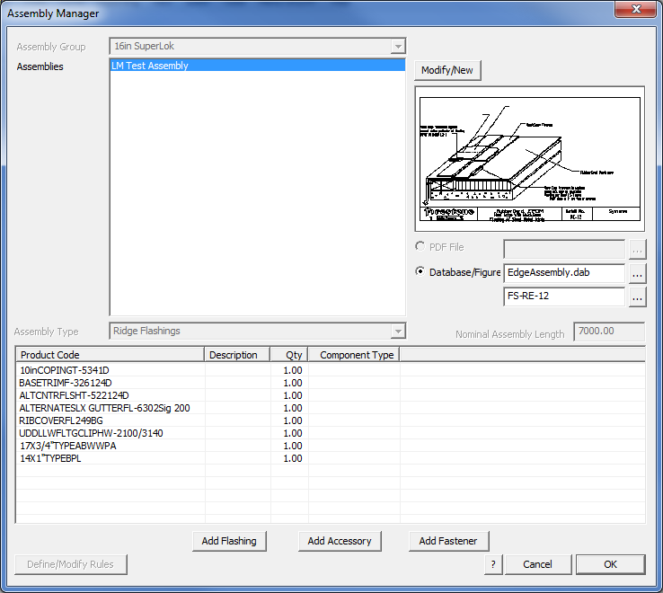
Assembly Groupings, Types, Nominal Lengths, PDF File and Rules are all disabled in non-commercial mode. Modify/New allows you to modify an existing assembly name or add a new assembly.
Selecting [OK] saves away the current assemblies list to the file EdgeAss.CSV.
Commercial Mode
In Commercial mode, the assemblies are assumed to be complex and that there will be many of them (typically > 500) and so the assemblies are stored in a binary format (non man-readable) for faster software access. Assemblies are grouped according to Assembly groups that must first be set up in order to define the binary files that assemblies can then be stored within.
Assembly Groups
To create an Assembly group, the user will go to the Set-Up -> Assembly-Groups menu and simply create a group by naming it in this dialog:
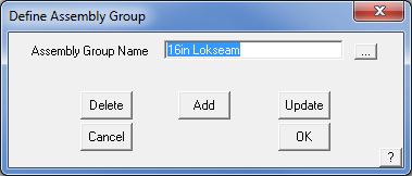
The creation of an Assembly Group then allows the user to link a group of Flashing Assemblies to a specific group of roofing or wall cladding panels when they are defined. This link may be made after panels have been defined and ‘Commercial’ mode enabled.
Assigning a Panel to an Assembly Group
In Commercial mode, roof and wall panels can be assigned to a specific Assembly Group. This is done by accessing the Set-Up -> Metal-Panels function and selecting the Assembly Group from the drop-down option in the dialog:
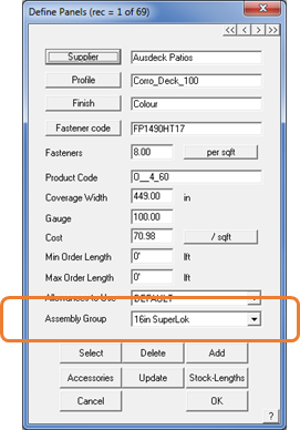
If you have no intention of using Assembly Groups, then you do not have to select an Assembly Group when you define your new panel profile.
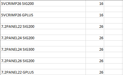
Alternately, the linkages between panels and Assembly Groups are stored outside the software in a file called SgroupLink.CSV. This file can be modified manually in a text editor or Excel, although care must be taken to use the correct product code from the panel and the index of the Assembly Group:
Assembly Manager
In commercial mode, the Assembly Manager takes on extra functionality. This functionality provides for Assembly Groups.
Assembly Group – Allows the user to select which Assembly Group we are looking at. Greatly reduces the complexity in numbers of Assemblies being modified. Modify/New allows the Assembly Groups to be modified, created or deleted.
PDF File – Instead of just a database/figure being specifiable to indicate how an assembly is to be installed, a PDF file can be specified for commercial customers. At a later stage in the process, the PDF files can be grouped together and printed en-masse to produce a document set for installation of this specific project.
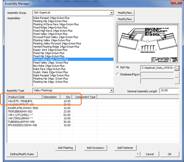
Assembly Type – Allows an Assembly to have a type assigned to it, so that it can only be assigned to certain line types within the software – for example, in the dialog above, the Assembly has been defined as a Valley type and as such, can only be applied to Valley lines on your model.
Nominal Assembly Length – Allows a notional length to be specified for the selected assembly for costing purposes, thereby making the specification of quantities for parts and pieces of the assembly much less complex. For instance, in many markets such as North America most assemblies are specified in 10’ length multiples.
Assembly Manager Rules
Rules can be created for Assemblies that allow the software to automatically swap parts in or out of an assembly, based on various decisions made during a project setup.
For example, let’s assume we have 5 different valley flashings, with the following product codes:
VALLEY22G – 22 Gauge Valley Flashing - Galvanized
VALLEY24G – 24 Gauge Valley Flashing - Galvanized
VALLEY22C – 22 Gauge Valley Flashing - Painted
VALLEY24C – 24 Gauge Valley Flashing - Painted
VALLEY24X – 24 Gauge Valley Flashing - Hi-Protective Coating
If we were to define an Assembly that used this flashing category, we would need to take into account all of the different valley flashing options of gauge and finish and create many separate flashing definitions to cover these. Instead, Roof Wizard allows us to define a flashing with variable values that might include universal variables that look like this – VALLEY@@% – where the @@ symbols are used to replace the product gauge at selection time, and the % symbol to be replaced by the material selected. This allows the product code for the correct flashing to be substantially simplified and automatically built up by the software.
Note that this process presumes that your product codes are organized in an orderly way. If the product codes in your organization are not organized in a sequential way as shown in our example, you will struggle to use the rules to reduce the number of assemblies you need to define. The product code structure you implement for trim and flashing items is key to the success of the Assembly Manager in managing huge component product lists.
Example Rules can then be set up similar to the following examples:
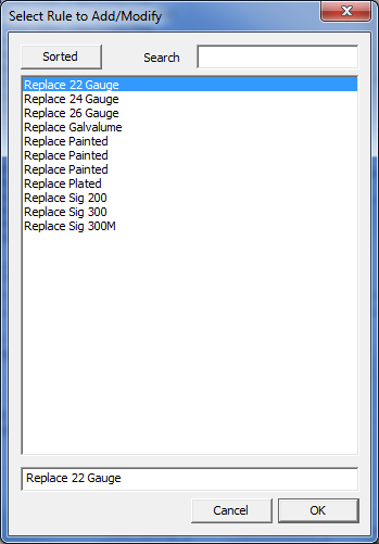
The first rule below tells the software to replace any instance of @@ in the Assembly Product Codes with the value of 22, when the gauge is 22. The second rule tells the software to replace any instance of % in the Assembly Product Codes with G if the finish of the product is set to “Galvalume Plus” as shown in the examples below:
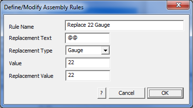
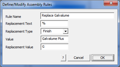
There is no practical limit to the number of rules that you can set. This makes for a very powerful tool to manage even the most complex roof and wall trim systems automatically.
![]()
NOTE: When setting up, start with simple examples and test that you have done it correctly before you launch yourself at the entire product list in your company.
Zones
The Cover > Zones function allows the operator to define areas of a roof where materials are quantified differently according to their respective locations on the roof. Typically, this function is used for calculating materials for retrofit roofing where wind loading must be accounted for. In areas prone to high wind and storms, the roof area is typically divided into ‘Zones’ where extra fasteners and battens/purlins are required to increase the wind load rating.
Field Zone Edge Zone Corner Zone
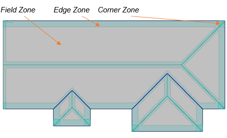
The process is straight forward and what follows describes the use of Zones for a typical retrofit situation.
Model the Roof and Insert Zones
First thing to do is model your roof geometry then select the menu option Cover > Zones. The following dialog box is displayed where you set up the zone offsets or spacing from the specified line types. When inserting the Zones, they must be inserted in the order indicated – that is, Corner Zones, then Field Zones and finally Edge Zones. Note that the lines must have an assignment of type. A ‘None’ line type will not create a zone offset.
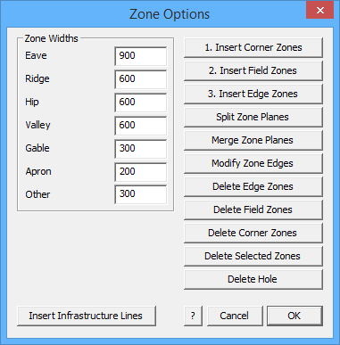
![]()
Note: Any plane in a model may be changed to a Zone plane and used as described above. This is done under Tools > Change > Plane Material.
First model the roof geometry.
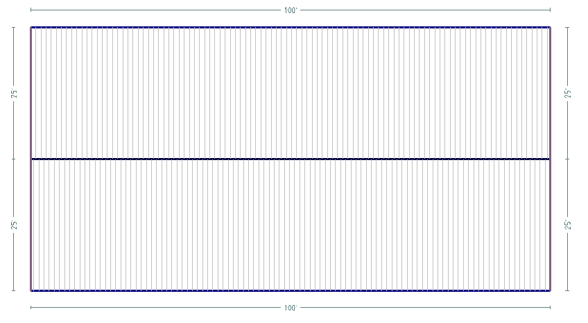
Select Insert Corner Zone(s) – all zones must be inserted in the order as numbered on the dialog box.
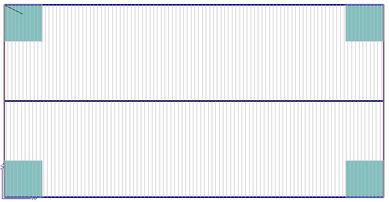
Select Insert Field Zone(s) – the operator is prompted to insert zones on Selected Planes or All Planes.
Field zones are inserted automatically based on Zone Option settings.
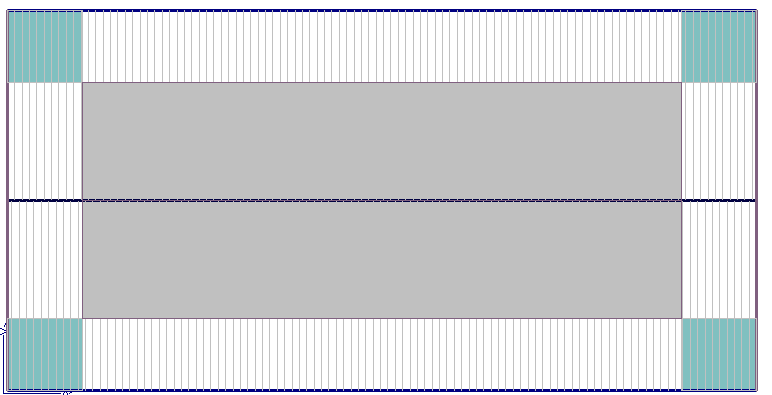
Select Insert Edge Zones and All Planes and the edge zones are inserted.
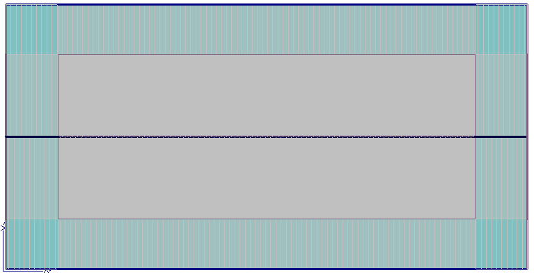
Once all the Zones are inserted (and the required materials defined), the lines representing the required roof systems materials must be inserted on the model.
Zones impact the use of materials and particularly, the use of additional fasteners based on the Zone definition. This requires the respective materials to be defined under Set Up > Flashings/Panels etc.
Typical Use of Zones
Insert the existing Purlins using Cover > Flashings > Purlin 1 (select and use Insert-Modify to insert them – refer to that section of the manual below [Cover > Flashing] for a detailed description of inserting Purlins). These become the primary structure for aligning and installing the new retrofit materials further constrained by the inserted zones.
Check Set-Up of Materials
You must also define line styles that suit the system you’re installing. In this example we will be using the Roof-Hugger® purlin system to describe the retrofit system.
Go to Set-Up > Preference Settings > Systems Preferences and set User line types such as Sub-Rafter, Sub-Purlin, Roof-Hugger® etc. While in Tools, it would be useful to check the line colour and style of the newly defined User defined line types – Set-Up > Preference Settings > Line Styles – so that they are clearly indentified on the model.
Extra User Defined Line Types


Change Line Styles to set your preference for line style, colour and weight so that the lines are displayed the way you wish to see them on your roof model.

For example, line style 4 is a dashed line.

Next go to Set-Up > Flashings and set up your roof huggers, sub-rafters and sub-purlins, based on the newly defined User lines.
Use the estimation options under Accessories to determine number of fasteners based on Intersection with Purlins, Sub-Purlins, Sub-Rafters etc. making sure that the correct accessory items such as clips and screws are defined as required, taking careful note of how these are associated with the flashing item.
For more detail please refer to defining Flashing/Trim.
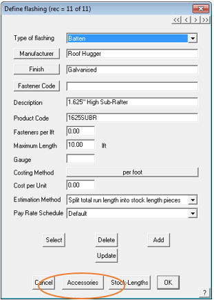
Selecting the correct Estimation Method is critical for accurate take-off of additional fixing items. These set up details only need to be done once.

They are now ready for use and re-use on all upcoming jobs.
Select Cover > Flashings. All line types currently on the model are listed. The next step is to insert the existing purlin system, if indeed that is required. Select the purlin to be inserted for Batten/Purlin 1 and select the Insert/Modify button. (If you are not concerned with the existing system, skip this step.)
Set the required intervals for the existing purlins and select [Apply All]. The existing purlins are inserted. Check that the Intermediate Spacing is correctly set for your situation – typically use Fixed Spacing.
The existing purlins inserted and displayed.
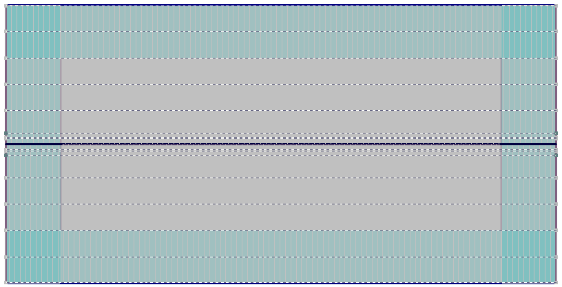
Zoom in to one corner to make it easier to find control lines. The next step is to insert the various infrastructure for the retrofit roof – the sub-rafters, sub-purlins and new roof purlins.
Go back to the Cover > Zones function. Select the [Zone Infrastructure] button so that you can insert the required sub-purlins and sub-rafters as specified by the engineering for this job. You apply these to each zone as required.

The following dialog is displayed which helps automate and control the insertion of retrofit structural items.
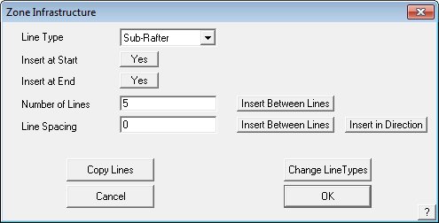
Line Type The type of line to be inserted
Line at Start Installs a line at the starting edge of the zone.
Line at End Installs a line at the end of the zone.
Then two methods of installing the lines; either –
Number of Lines The number of lines to be installed across a zone area spaced evenly between the start line and the end line.
Insert Between Lines The operator is prompted to select the Start Line and the End Line.
Line Spacing Uses a fixed spacing as defined here to insert the lines.
Insert Between Lines The operator is prompted to select the Start Line and the End Line.
or
Insert in Direction The operator indicates the direction the lines are to be inserted at the specified spacing.
Copy Lines Allows the operator to select all lines in say, a corner zone, to another corner, thus speeding up the process of doing multiple corners that have identical structures.
Change Line Types Allows the operator to change one line or multiple lines from one type to another – eg Sub-Rafters to Sub-Purlins.
In this example if we were to install Sub-Rafters first, then select that Line Type in the Zone Infrastructure dialog, then the number of lines and select the [Insert Between Lines] button. Select the left-hand edge of the Corner Zone, then the right-hand edge of the corner zone, the Sub-Rafters are inserted.
Existing purlins Sub-Rafters (Short vertical lines) Sub-Purlins (Short horizontal lines)
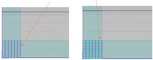
With the Sub-Rafters and Sub-Purlins inserted in the Corner Zone, the operator can now copy the whole set of lines to the other corners. Select the button, Copy Lines. Select the lines to copy and then following the prompts for start point and end point, snap the required points with the middle mouse button.
The final step in inserting the lines for our retrofit structure, are the new structural purlin lines.

Set the Line Type (eg Roof-Hugger purlin) then the spacing as determined by the existing purlins (5 feet) and select the [Insert between Lines] button. Select the lower existing purlin and the upper existing purlin and the new purlins are inserted.
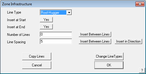
Represented by the bold lines. If for any reason the new lines do not align perfectly with the underlying existing purlin spacing, the new lines can be deleted and reinserted or even manually moved.

Redo this same process for the opposite side of the roof and the project is ready to be bid and the material cut list produced. The line types should be checked and the best way to do this is use Tools > Show Line Types in the ISO view.
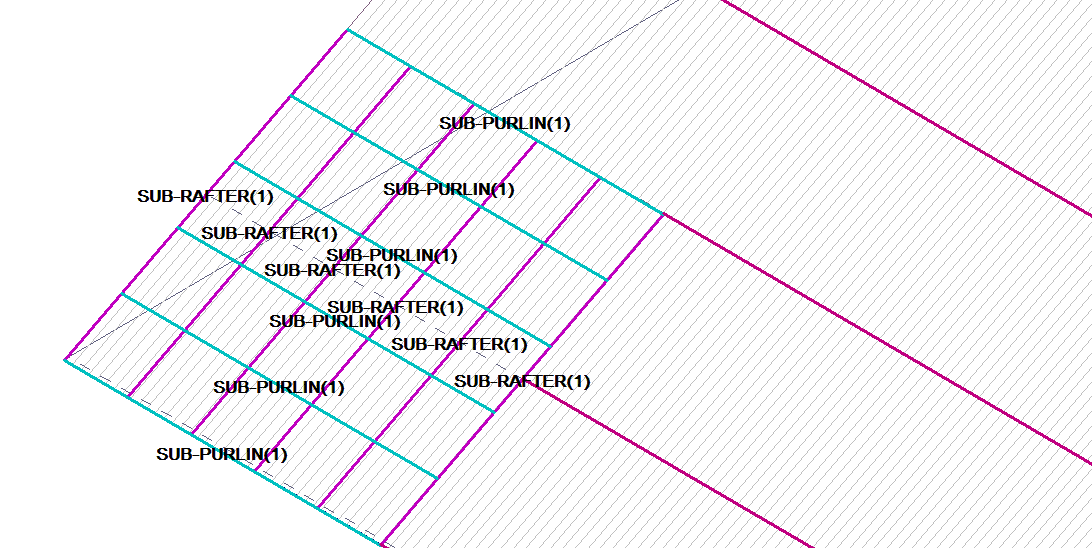
Select Cover > Flashings and the Select Trim dialog is displayed. Now that the new roof structural lines have been added to the model, they are listed as options.
Select the required material to be installed on the new lines and then select [Generate].
A more detailed description of the function of generating flashings and trim can found in the Cover > Flashings section below.

The correct material list is now displayed entirely automatically and with exactly the correct numbers for that job. The operator my now proceed to insert roof panels and roof trim for ridge and eaves over the job to complete the bid.
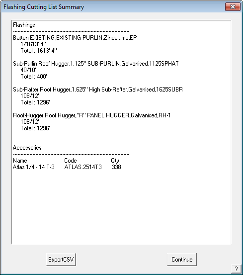
Stage-Manager
[Pulldown Menu Only]
Stage Manager is a process by which you can group together different parts of the job. Based on your preference settings, Stage Manager is either always on or always off. You would employ Stage Manager because:
- you want different installers for different sections of one job;
- you want materials for one part of a job ordered and delivered at different times;
- you want to quantify materials for a specific part of a job;
- you want to present your customer with quotations dealing with different stages;
- you want to present your customer with staged orders or invoices.
Once grouped, the job can be costed and ordered by stage. Stage Manager provides comprehensive control over ALL aspects of the job and the materials.
Stage Manager may be turned on or off as required and this is set under Set Up> System Preferences. If you do not use Stage Manager functions, it is best to have it turned off as the extra steps do cause a small degradation in the speed of processing larger jobs, since Stage Manager controls all subsequent reporting processes in the software. It can also unnecessarily complicate a job. You can also turn on or off Stage Manager from the Stage Manager screen by selecting the SM Enabled/Disabled button.
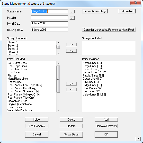
When you select Cover > Stage Manager, the Stage definition dialog box is displayed. This command lets you define a stage and set which items are included from what storey for each new stage.
Type the stage name and the installer’s name. Set the required dates as appropriate. Next you select the storey to be included in this stage then select the items that are required to be installed from this storey as part of this stage.
As each group of items is selected, it is displayed in the ‘Items Included’ pane of the dialog box and the storey number that it is to be included with this stage – ie Roof Planes [S2] indicates that only the roof planes for storey 2 are to be included whereas Barge Lines [S1,S2] indicates that barge cap will be included for both storey one and two.
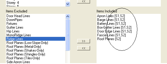
Stage name This is the name you want to call the stage (eg Main roof, Fascia and Gutter or Stage 1, Stage 2 or Top Roof, Bottom Roof etc.)
Installer This is the name of the installer for this stage. When you click the ‘…’ button, you can select the installer from the list of installers defined under Job Info from the Pulldown menu.
Install date This is the date you want this stage installed
Delivery date This is the date you want the materials delivered to the site.
Select This button lists the existing stages you have defined in this job and lets you select one.
Delete This button will delete the currently selected stage
Add This button adds a new stage.
Update After you select a stage, the update button updates the current stage with the new details.
[Cancel] This button cancels the dialog box without saving changes
Set as Active Stage When you start a new job, the stages are loaded from this file
[OK] This button will save the stages in the current job.
Remove-Elements This command lets you remove individual geometric elements from the stage already defined in the job.
Show Stage This button highlights all the roof items included in the stage being defined.
The stage definition information is stored in a text file called Stages.dat. It is in the form of:
Stage 1
0
17 April 2009
10 April 2009
0
Roof Planes
0
Ridge Lines
2
Hip Lines
2
Valley Lines
2
Fascia Lines
3
…… etc
The item category is listed, followed by a number indicating if that item is included in the stage and from which storey, in a mathematical progression.
A zero indicates not included in the stage, a 1 indicates storey 1; a 2 indicates storey 2; a 3 indicates storey one and two; 4 indicates storey 3 only etc. As this progression is automatically determined by the software from the input to the dialog box as shown above, the operator does not need to remember how this works.
![]()
Note: With Stage Manager enabled, ALL Reporting processes are controlled by it, including the generation of cutting lists, orders etc.
Take the example where a job is being developed according to stages, the required stages have been defined and the operator wishes to extract orders for material for Stage 1.
Select the Reporting > Supply+Install option. If a quotation has previously been saved, then the operator will be prompted to open a previous quote, or Re-Calculate quote. If this is a new job, you will go straight to the ‘Select Stage’ dialog. Assuming we wish to determine a new set of reports just for Stage 1, then we would select ‘Re-Calculate quote’.
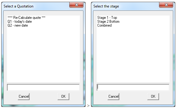
The software then prompts the operator for which stage is to be reported on – in our example we would select Stage 1. Regardless of what was previously done on the job, the materials for the whole job are then re-calculated from scratch, all the trim and roof cover etc. and the results displayed in the Supply+Install dialog box. The results will be just those materials necessary for this stage and any items defined as Extras, and nothing else. This quotation can be saved, and the process repeated for Stage 2 and saved. Once the operator is happy with the quotations for each stage, then the required reports and drawings may be printed.
The Stage Manager process can become quite complex and does impact on the final result dramatically, so careful thought must be applied to ensure all the stages are correctly defined. If there is any doubt, delete the stage and start again.
Test the definitions and the results on a simple ‘test job’ that is representative before using it on any real job. Create a model that has multi-levels and storeys and all manner of trim types. Become familiar with the job so that you know what to expect. If the result works for the test job, your confidence in the Stage Manager will increase substantially.
In any case, the operator should use all their skill and experience to check the job carefully – the software is only doing what you tell it to do.
IMPORTANT NOTE – Stage Manager Default Files
The Stage Manager has been set up to default to pre-defined flashings if none are selected at the start of your project. What this allows you to do is model a roof, select the roof material and go straight to the Supply and Install summary page. If Stage Manager is turned on in System Preferences, then the Stage Manager code will look for the default flashing definition file (RoofFL2.CSV) and apply those flashings to the job and calculate the cost, automatically.
The intent is to save time extracting a detailed quotation by not going through the Cover > Flashing / Generate Flashings process, but beware, Stage Manager may impose the wrong trim package to your roof, if you are not paying attention.
As soon as you go to Cover > Flashings and generate the trim for your roof, that set of materials is used instead.
If you do not wish to have Stage Manager select the trim for you, go to Cover > Flashings; set all fields to [None]; and select Save As – and select [System Default]. The default system will then have no flashing pre-selected, and flashing will only be applied after you have selected it and run Generate.
If you select any other flashing system, or your own flashing package, then this file is ignored.
- Zones
- Underlay
- Tapered (Metal) Panels
- Tally Panels
- Tally Blocks
- Stage Manager
- Set Panels
- Select Tile +
- Select Tile
- Select Metal
- Select Membrane
- Panel Allowances
- One Roof Plane/One Roof Panel/Reset Plane
- Modify Panels
- Modify Offcuts/Tally Offcuts/Delete Offcuts
- Modify Blocks
- Linear Nesting
- Insulation
- Generate Panels
- Generate Offcuts
- Generate Blocks
- Flashings
- Flashing Assemblies
- Fixture and Fixture Array
- Fall Protection
- Export to Rollformer
- Downpipes
- Delete Blocks
- Block Cutting
- Auto Blocking 2


