Contents
Estimate

The Estimate set of commands provides you with the tools to estimate metal panels on a roof. Indeed, it is only relevant to metal roofing. It is assumed of course, that you have already modelled a roof.
The estimation process involves two basic steps:
- Setting the allowances, such as gutter overhang, rounding up, annotation options, etc.
- Determining the panel/sheet estimation method you wish to use and then applying it
This will then result in a panel/sheet list. Commands are also provided to insert and change lap-direction arrows so that the installers install the panels as required in your specification.
The Metal Panel Estimation Methods
There are four panel estimation methods provided. These methods are called:
Blocking methods – Auto-Block or Block-Cut
Generating Off-cuts
Generating Panels – with Linear Nesting (of panels)
You would choose the estimation method based on the profile of the panel/sheeting material, as well as your preferred on-site installation processes.
![]() VERY IMPORTANT NOTE: Not all methods suit all materials, and most important of all, these different estimating methods ARE NOT interchangeable. What this means is that if you wish to estimate with a different method then you must completely delete the method just used, then apply the alternate method. For example – You MUST not apply Gen-Panels over the top of Auto-Blocking.
VERY IMPORTANT NOTE: Not all methods suit all materials, and most important of all, these different estimating methods ARE NOT interchangeable. What this means is that if you wish to estimate with a different method then you must completely delete the method just used, then apply the alternate method. For example – You MUST not apply Gen-Panels over the top of Auto-Blocking.
 Panel Allowances
Here you can set the standard allowances you want to apply for clearances or setbacks for the roof panel or sheet around ridges, hips and valleys. Also you can allow for gutter overhang and the thickness of the battens in calculating the resultant panel lengths. These values are used by the Estimate Offset-roof command to generate the new roof planes.

Offset-Roof Parameters
Gutter Overhang This is the amount to add to the panels for overhang into the gutter. It is also added automatically to blocks.
Box Gutter Clearance This is the amount to add to the panels for overhang into the box gutter.
Hip Clearance This is the clearance you want along a hip
Ridge Clearance This is the clearance you want along a ridge
Gable Clearance This is the clearance you want along a gable
Valley Clearance This is the clearance you want along a valley
Apron Clearance This is the clearance you want along an apron
Batten Thickness This is the batten thickness from the rafter to the underside of the sheet/panel. This may also used to define the thickness of insulated metal panels so that the correct panel length is calculated.
Blocking-Options
Show Pitch on Block Label [Y/N] Simply Yes or No to having the roof pitch shown.
Round Panels in Each Block [Y/N] Rounds the number of roof panels or sheets to a whole number in the initial pass. This effects both regular ‘Blocking’ and ‘Block-Cut’ methods of cutting list creation. This displays the actual number of sheets/panels and may be larger than the plane based measured rectangle of panels.
If you select No, then the panels of the same length are totalled at the end. This results in one or two sheets of each length less. A very tight result without room for error on the job site.
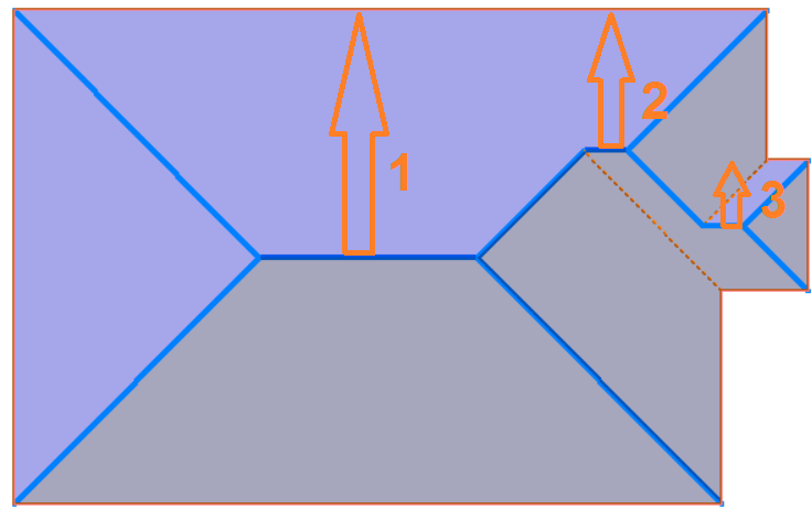
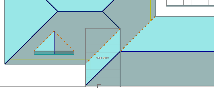
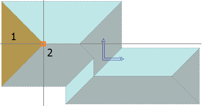
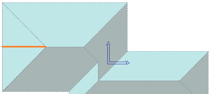
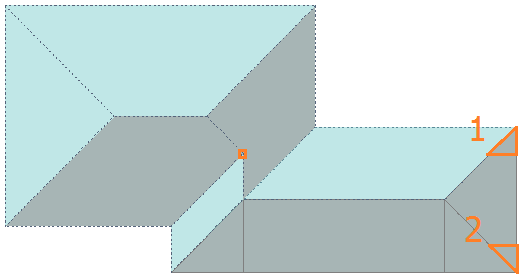
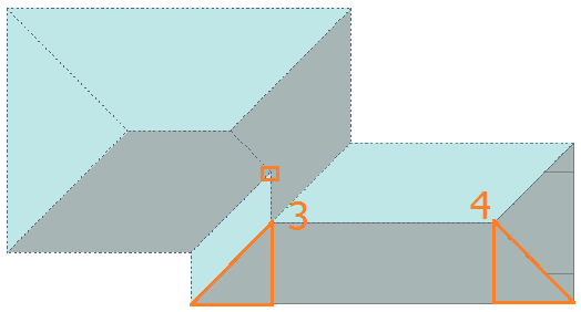
Reducing the Width of Straight Blocks [Y/N] Effectively, what this function is doing is looking across the width of a run of eave, in case of the illustration below, the combined width of Block 1 and Block 2 and determining the number of panels/sheets required to cover the roof and compares that with the number determined by the number of panels/sheets in each block.
In the example, Block 1 would require 6.6 panels and Block 2 would require 5.3.panels. If each block is rounded then the total number of panels supplied would be 13 (7 panels in Block 1 plus 6 panels in Block 2). If it is accepted that rounding the whole run instead of each block would work for the job, select Yes, then you will supply 12 panels – the over supply of the longer panel in Block 1 will account for the under supply in Block 2 (7 panels in Block 1 and 5 panels in Block 2).

Rounding the Sheets in Each Block [Y/N] By selecting NO, it will treat each block of same length sheets separately, and only round up once they have all been grouped together. e.g. 3.6 @ 3000, 2.2 @ 3000, will calculate 3.6 + 2.2 = 5.8 rounded to 6 sheets @ 3000mm.
If you select YES, each block is rounded up before being grouped together. e.g. 3.6 @ 3000, 2.2 @ 3000, will be rounded up first to 4 @ 3000 and 3 @ 3000 and calculate 4 + 3 = 7 sheets @ 3000mm.
By selecting NO it will not reduce the widths.
If you select YES, it will calculate the total length of the eave defining the length of the block(s) and divide it by the panel/sheet width. If this number is less than what has been calculated without reduction, it will use the smaller number of sheets. This process only works when Rounding is turned on.
Holes in Roof Planes The options are Ignore All, or Ask Each Time. If you select Ask Each Time, the software prompts whether a hole in a roof plane needs to be taken into account while blocking.
Drawing Style of Block The options are Original or Block-Cut. The Block Cut allows the blocks to extracted and sub-divided using the Block-Cut method.
Block-Cutting Text Size As the software generates the sub-divided blocks, they are annotated. This sets the text size so that it can be more easily read in the field when turned into a report using your template.

Generate-Offcuts Options
Show Pitches [Y/N] – Displays the pitch with the annotation of the off-cut areas
Show Panels [Y/N] – Displays the number of sheets in the off-cut group


Annotation Format [Abridged/Standard] – The standard output is displayed above. The abridged version of the annotation is shown below. This is designed to show the same information but in a shortened form to make the field drawings easier to read – as shown below:

Generate-Panels Options
Panel Side Underlap Distance This is the distance one panel is overlapped by the next panel. This is the amount subtracted from the overall panel width.
![]() NB – This would always be set to zero if the panel width is defined as the cover width or exposure of the panel. The only situation where this is set to any other number is when you use factory pre-cut or angle cut sheets. The side lap value defaults to 0.0. The Panel Side Underlap Distance is greyed out in the Metal Panels > Allowances dialog, unless the user inserts a blank/empty text file entitled “SIDELAP.DAT” in the ..\User folder. This is set for just two of all our users – these guys do angle cutting in the factory and the panel width is adjusted so that the correct angle of cut is calculated.
NB – This would always be set to zero if the panel width is defined as the cover width or exposure of the panel. The only situation where this is set to any other number is when you use factory pre-cut or angle cut sheets. The side lap value defaults to 0.0. The Panel Side Underlap Distance is greyed out in the Metal Panels > Allowances dialog, unless the user inserts a blank/empty text file entitled “SIDELAP.DAT” in the ..\User folder. This is set for just two of all our users – these guys do angle cutting in the factory and the panel width is adjusted so that the correct angle of cut is calculated.
How it works – You set the panel to the coverage width (say 761mm) and then add an underlap/sidelap amount in the panel Allowances (say 91mm) which is ignored from a panel layout perspective, so the panel layout on screen and in the report templates is correctly represented. The panel underlap is applied at nesting time (Estimate > Linear Nesting) to ensure panels are nested as per the full fabrication width (761+91 = 852mm) of the panel and the PCF file for each job is created and sent to production for the anglecut machine (which nests and cuts full fabrication width panels).
Show Panel Direction Arrows [Y/N] Allows the lay direction arrows to be shown, and printed on the report.
Panel Lay Direction Sets the lay direction of the panels. May be left to right, right to left or optimised. Optimised will select the best direction based on the most logical starting edge, such as the gable end, for example.
Tally-Panels Options

Combine Similar Length Sheets After you generate a sheet list, sheet lengths which are less than this amount apart, are assumed to be the same length and are merged together. The shorter lengths are merged into the longer lengths.
Round-Off Sheets to Next (mm) This can be defined as any number, it will then round up to that number. If you don’t want it to round up at all you need to set it to -1, as 0 will be rounded to the nearest 10mm.
Note – if you are using ‘Stock Length’ panels, such as long run tile profile metal roofing, then rounding must be set to the multiple of stock lengths available – eg 300mm or 500mm. (Refer [Split Panels] function below).
Annotate Panels With Here you can set how you want to annotate the drawing of the panels. The options are the identifier for each panel when you generate the cutting list using Estimate > Tally-panels.
You can have the Panel Identifier Only, Panel Length Only, Rounded Panel Length Only, Indentifier and Panel Length, Identifier and Rounded Panel or Nothing. The panel length is the length calculated by the software and adjusted for the allowances. You may also annotate the panels with the rounded up sheet or panel length adjusted by the operator under the Modify-Panels > Cha-Panel-Len option or the rounding set in the Allowances dialog as described above under Round-Off Panels.
Annotate Text Size The size of the text as it will appear on the reports. The size is in millimetres. If you work in Feet/Inches, the text size is still millimetres.
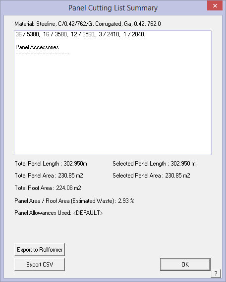
Apply the minimum panel length [Y/N] If you have set a minimum panel/sheet length, would you like it to be applied or not? Any panel length below the minimum panel length specified for the profile in use, will be combined to create a series of panels longer than the minimum length. The minimum order length is defined when you define each panel under SetUp > Metal Panels. When the Panel Cutting List Summary is displayed, the make-up of the combined lengths is displayed, as shown below.

Combine Min. Len. Panels This function provides for various methods of combining all the short length panels/sheets that can become a nuisance for manufacturers, especially how to pack them, and for installers. It only works if ‘Apply the Minimum Panel Length‘ option described above has been set to [Yes].
The options are to combine the short lengths into a series of panels that equal the maximum specified length; to combine the short lengths into a series of panels that equal the minimum specified length; or every short length less than the specified minimum length is simply ordered as a minumum length panel, that is – a 1’6″ and 2’2″ and 2’9″ all become 4′ panels if 4’ was the specified minimum length.

Let’s look at a simple example. We selected a panel where the minimum length was set at 400mm (15.75″).

With the Combine Min. Len. Panels set to [Combine for Maximum Lengths] you get the following sort of outcome (Combining all until you reach the maximum length, at which time you will get x number at 2200 and the rest combined to whatever length is less than 2200):

With it set to [Combine for Minimum Lengths] you get the following (combining minimum length panels until they are larger than the minimum length at which point it marks off on them and then starts a new amount):

The [Each Panel becomes Min. Len] then you get the following (each panel shorter than the minimum lengths becomes the minimum length):

In each case, only the full tallied members of the roof are highlighted on the model. The short panels (less than the minimum length) aren’t highlighted to show that they’re not represented separately (1:1) in the cutting list:

The minimum and maximum order lengths are defined when you define each panel under SetUp > Metal Panels.
Move Text for Sheets Shorter Than This number sets the length of sheet/panel where the annotation gets placed automatically beyond the borders of the roof model.

Should the location of the annotation still be difficult to read, a function exists to move the annotation and the leader line repositioned to suit. This is found under Estimate > Generate Panel Layout > Modify Panels option which displays the following dialog. Select the option Move-Text and the prompts guide you through selecting, moving and moving the text and reposition the leader line. A further button also provides for deleting or adding a leader line.
Add Square Brackets to Sheet Dimension [Y/N] provides the opportunity to remove the square brackets around the panel lengths.
Apply Offset Values without Offsetting [Y/N] This allows you to get the cutting list for the panels, as if the offsets had been applied, even though the offsets are not drawn on the job.
Manually Tally Panels [Y/N] allows users to turn off automatic tallying for larger jobs or for specific panel types.
Load This button allows you to load a pre-defined set of allowances for the particular roof system.
Delete Deletes a pre-defined allowances file.
Save-As Allows the operator to define allowances for a particular roof system and save that for future jobs. You may have as many allowance files as you have roof systems. Indeed, an allowance file is typically specific to a panel profile.
When you click [OK], these values are saved for use in all jobs.
[Cancel] quits the dialog box without making any changes.
Generate Blocks
 Auto-Block
This command constructs rectangular blocks across a roof shape using the roof geometry to generate the sheet/panel cutting list. There are actually two Blocking Methods that may be accessed from the Estimate menu – Auto-block 1 and Auto-block 2. Auto-block 1 is the process activated from the Icon menu.
![]() Note: The Icon menu starts Auto-Block 1. The Auto-block 2 method accessible from the Pulldown menu should only be used if the estimator understands the process and how the result will be employed by the installers.
Note: The Icon menu starts Auto-Block 1. The Auto-block 2 method accessible from the Pulldown menu should only be used if the estimator understands the process and how the result will be employed by the installers.
You should experiment with both methods for the jobs that you do. Each has a slightly different algorithm with quite different results, depending to some extent on the roof shape. AppliCad makes no recommendation as to which is the better blocking method. Each produces a result that replicates the methods used by estimators in different markets and you may not agree with the result.
This method is only feasible with certain profiles that maybe split and flipped etc. It is not practical for profiles such as standing seam for example.
The variation in result is the nature of these techniques. Everyone has their own methods and the slight variations can create striking differences in the resultant cutting lists. The Modify Block options are important tools that allow you to modify the result to provide the output that you are satisfied with. It should be noted that the Blocking tools will give the right result for the majority of jobs and you should expect to intervene in the balance of jobs. You may decide to manually draw the blocks on the whole job. That is what the tools are there for, so don’t be disappointed.
After you click the Auto-Block command, you are prompted with the following dialog box.
The two options you have relate to how you want your sheets “Optimised”, if at all.
After you click [OK], then the blocks are generated. If there are blocks already on the roof, they are first deleted.
After the blocks are generated, they are annotated with the number of sheets, sheet length as well as the pitch. There is also a hatching automatically applied to each block so they are identifiable. Also, the coverage direction of each block is defined by the side of the block which is highlighted (a fatter orange line).

![]()
Note: the automatic blocking algorithm has been enhanced and simplified. It may be found on the pulldown menu at Full Job > Estimate > Blocking > Auto Block 2. The results may better suit certain situations, but the operator must be very clear as to the impact of the technique on the installers. It creates a much simplified Block sequence and in many cases, further reduces the waste and the number of panel/sheet lengths.
Auto-block2 uses an algorithm that effectively breaks the entire roof area into rectangular areas. This is different to Auto-block1 which effectively divides the roof into triangles based around the hip end and then combines the triangles into rectangles. The rectangles are then divided into roof sheet widths to determine the number of sheets required.
The cutting list results between the two methods can be dramatically different on some jobs, and almost identical on others.
 Modify Blocks
This menu item displays a sub-menu, which provides a set of commands allowing you to manually insert and adjust the blocks. If you currently have blocks turned off, they are automatically turned back on.

Insert-Rect
This command lets you insert a block by digitizing two points.
After you select this command, you first select a line which orients the block correctly. Then you enter the storey to which this block relates then the pitch for the block. Then you digitise 2 points which define the block extents. After you have located the second point, the block is drawn.
Now you are to select the side (line) which defines the coverage direction. Once you have done that, the number of sheets, sheet length and pitch is annotated on the block. The coverage direction defines the direction the sheets are to run, and therefore the number and length of sheets for this block is totally dependent on the orientation of the coverage direction line.
Normally, the block orientation is square to the screen. In actual fact it is square to the construction plane (CPL). The CPL defines which direction is x and which is y. If you need a block to orient itself such that it is not square to the screen, you’ll have to change the CPL orientation using Drawing CPL Change 3-Points.
![]()
Remember: the size of the text that annotates the block can be changed by using the View > Plot-Scale command. The larger the value, the larger the text will be – most residential plots are best viewed at 1:100.
The following diagram shows the insertion of a block as a rectangle. The first digitise defines the alignment, d2 and d3 define the extent of the rectangle, and d4 defines which side of the block is the coverage direction.

This second example shows how you can insert the block, aligned to any direction.

Insert-Line
This command lets you insert a block by selecting a line. The line defines the bottom left and top right hand corners of the block. Normally you would select a hip or valley line to insert the block.
After you select this command, you first select a line which orients the block correctly. Then enter the storey to which this block relates then the pitch for the block. Then you locate the line which defines the extent of the block. After you have located the line, the block is drawn.
Now you select the side (line) which defines the coverage direction. Once you have done that, the number of sheets, sheet length and pitch is annotated on the block.
The following 2 examples show the same result as above but select the hip line as the basis for the block.


Extend-Edge
This command allows you to move an edge of a block, in effect re-sizing it. To extend an edge, simply click on the edge to move, then snap onto a point. After that, the edge is moved so it goes through that point, and the annotation of the block is updated.

Rotate
This command allows you to change the edge which defines the coverage direction.
Simply click on the block and you will notice, the coverage direction rotates to the next edge.
![]()
Note: There is no difference if the coverage direction line is the line on the opposite side of the block.

Change-details
This command allows you to change the details for selected blocks without changing the physical size of the block. After selecting this command, you are then prompted to locate the blocks to change. You locate the block by clicking on the hatch lines which cover the block or by selecting a window around the blocks.
Then the block details dialog box is displayed.

Here you can change the number of sheets and the sheet length for that block.
When you click [OK] the change you made is annotated on the blocks you selected.
If you modify the block with another command (such as Extend-Edge or Rotate), the original values are restored.
![]()
Note: The values you see annotated on the block are the actual values accumulated to form the final sheet list. You can therefore use this command to alter your sheetlist if you desire.

Change-Lengths
This command allows you to change the lengths of selected blocks. After you select the blocks you want to change, the Change Block Length dialog is displayed.

When you click “[OK]”, the length you enter is applied to the selected blocks.
Add-to-Verandah
This command allows you to apply a block to a bullnose verandah easily.
After you draw the bullnose verandah, you then insert a block to cover each segment. At the moment, the block has not taken the curve of the bullnosed into account.
Then, to take the bullnose into account, you first select the verandah in question, then the block to effect. The block sheet length changes to take the curve into account. You should only perform this once, as it simply adds the difference between the straight length and the curved length.

Change-Pitch
This command allows you to change the pitch of block. After you have changed the pitch, the effective length of the sheets is changed to suit.
To change the pitch, select the Change-Pitch command, then the particular block. Then you are prompted to enter the new pitch. After you click [OK], the effective sheet length is recalculated and annotated on the block.

Show/Hide-Pitch
This command allows you to turn on or off the reporting of the pitch for the blocks.
Show-Blocks
This command simply applies a hatch pattern to all the blocks in the model. You would use this to be able to visualize the blocks as well as being able to select the blocks easily.

Hide-Blocks
This command simply turns off the hatching from the blocks.

Delete-One
This command lets you delete blocks one by one.
Delete-All
This command deletes all the blocks in the model.
Verify
This command reports information about a selected block in the prompt area of the screen.
Merge-Blocks
This command automatically merges (combines) 2 or more blocks which share a common edge as well as having the same coverage direction. This process automatically checks all blocks in the current model.
This is performed automatically in the Auto-Block command and you should perform it if you have inserted any manual blocks.

Reduce-Runs
This command removes sheets from blocks based on proximity to other blocks.
It does this by first creating runs of blocks. A run is a set of blocks which abutt each other. Then it determines the overall physical length of the run and calculates the number of sheets required for this run. It then compares this value with the sum of the sheets associated with the blocks.
If there are more block sheets than run sheets, that number of sheets is removed from the annotations starting with the shorter length sheets.
This is performed automatically in the Auto-Block command and you should perform it if you have inserted any blocks manually.

Mirror
This command lets you mirror a block around a line. After selecting the block to mirror, you then select a line to act as a mirror axis. After selecting a line, the new block is drawn. Keep in mind that the new block will display the number of sheets and length of each sheet as per the physical size of the block. Therefore, if you had changed the details the original block they will not be the details displayed on the new block.
Copy
This command lets you copy a block to a new position. After selecting the block to copy, you then select two points which define the amount to move the block. After selecting the points, the new block is drawn. Keep in mind that the new block will display the number of sheets and length of each sheet as per the physical size of the block. Therefore, if you had changed the details of the original block they will not be the details displayed on the new block.
Move
This command lets you move a block to a new position. After selecting the block to copy, you then select two points which define the amount to move the block. After selecting the points, the new block is drawn. Keep in mind that the new block will display the number of sheets and length of each sheet as per the physical size of the block. Therefore, if you had changed the details of the original block they will not be the details displayed on the new block.
Measure
This is a short cut to the Tools > Measure dialog to save time jumping in and out of main menus.
 Tally Blocks
This command creates a sheet list from the blocks in the model.
It does this by accumulating all the annotations from each block in the model to create a consolidated list. You should have already set the cover for this roof, but if not, you will be prompted to do so. The lists will separate straight sheets from curved sheets.
The Sheet Allowances Used: <xxxx> indicates the name of the sheet allowances file being used on the job being reported. This is set when you select your sheet/panel type before blocking. Select Allowances under Estimate and define the settings that work for your roof system. You can have multiple allowance files for different roof systems, such as corrugated or KlipLok.
After the sheets are gathered, the sheet cutting list summary dialog box is displayed, showing the number of sheets of each length, adjusted (if specified under allowances) for the rounding factor – in this case to the nearest 5mm. Note that the total length of coil required from inventory is also displayed, the total panel area compared with the total roof area with panels on it which gives you a waste amount as a percentage. You may set up various panel allowance files for different types of panel and these may be saved for later use. The allowance file in use is displayed for your information – in this case we used the [default] allowance file.

[Export to Rollformer]
The cutting list maybe exported in a file format for specific roll forming machines:

Select the required roll former controller format and select [OK]. The cutting list is instantly written and available to be sent with your job information.

You can also see on the summary, the total sheet length, sheet area, total roof area and block area. If you want to export this list to a comma separated value file (.csv) for import into another computer system, click ExportCSV.
[Export CSV]
The Export Panel Lengths option in the software from the Tally-Blocks menu allows the user to specify whether the output to a CSV should be split by Storey.
The default value for “Combine Storeys” is set to “Yes”, setting the value to “No” will split the panel length output by storey.

![]()
Remember : if you want to alter the final sheet list you can use the Man-Block > Change-details option.
 Delete Blocks
Allows you to delete all blocks with one click so that you can start again or use a more appropriate method of waste minimisation for that roof shape.
Note for when you are setting up your report templates: Use the key text string ###SheetList to display the panel lengths in a table on the report.
Now let us explore the most powerful of our sheet waste optimisation routines – Block-Cutting. Not only does this method allow you to work out the best method of laying the panels, but the report is produced to share this information with the installers.

 Block-Cutting
A development of the long established ‘Auto-Blocking’ process is available where the estimator determines where roof sheets can go and more particularly, shows where the offcuts must go, as part of a block, to substantially reduce waste material – this is called ‘Block-Cutting’.
 Developing a block-cut layout drawing is an interactive process that may result in multiple ‘correct’ results. In many respects this is what makes learning how to do this quite difficult – there is often more than one correct answer.
The first thing to look at is how many different ridge-to-eave lengths are there? In this example, there are three, so we are aiming for three sheet lengths in our sheet order cutting list or pack.
It takes the blocks created and allows the operator to identify roof plane areas, block-pieces effectively sub-dividing the block to account for each roof plane, and to show on the block where each off-cut is expected to be extracted from and applied to the roof plane.
This Block-Cutting process is taking what roofing installers (at least those who reduce waste by flipping sheets around) actually do in the field and shows them exactly how to achieve the best fit, before they get to the job site. It is an interactive process that is ‘driven’ by the operator to get the required result.
Block-Cutting Tools:
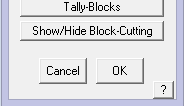
The detailed description of Block-Cutting process and the functions of the dialog box are below. The Block-Cutting dialog box also provides additional functionality for navigating the model and the Block-Cutting process from within the Block-Cutting dialog, while maintaining a slim-toolset dialog that allows for as much modelling space for the estimator as possible.
The measure routines for measuring between 2 points and also the length of a line have also been added to assist users to stay in the Block-Cutting process without having to step in and out of the dialog.
 The [Check Model] and [Delete Free L/P] are the standard Tools > Check Model functions made more accessible during the process of setting up a Block-Cut job.
The [View Plot Scale] button allows for the modification of the annotation text relating to Block-Cutting, without modification of the blocks (panel numbers etc.) themselves.
The [Save Model] button allows users to save the current state of the model without the need for quitting out of the Block-Cutting process. This button is useful for breaks in work such as lunch, long meetings where estimators do not want to exit out of the block cutting process but want to make sure their work is backed up.
 The [Block Cutting Dimension Reference] button adds the functionality of Panel Labelling, by providing a dimension insertion option within Block-Cutting, as well as adding the block reference into the dimension. Note – the [Dimension Reference] function must be enabled in System Preferences for it to appear in the dialog and to use. Read about it in System Preferences so that you understand the purpose, before you turn it on.
The same applies to Flashing annotation, with the additional functionality that flashing labels can be grouped by just their length, or additionally by a line also. If set to this latter option individual lines, despite having the same flashing type and length, will still have a separate identifier so that they are more easily identified on the drawing, and where the material is to be installed on the roof, thus greatly assisting the installers position materials around the job.

See example below for a Soaker Flashing along a Step line.

The Block-Cutting Process
The Block-Cutting process can be loosely broken into three steps –
- Define the Block;
- Place the Block and
- Assign Roof Plane block-pieces.
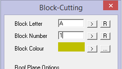
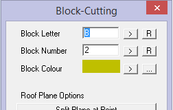
Select Estimate > Block-Cut to bring up the Block Cutting dialog. Set the first Block Letter, colour and number. If a roof panel has not been selected, then you will be prompted to select one from your previously defined panels.
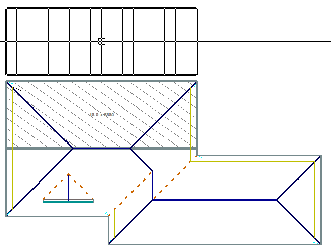
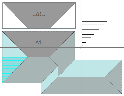
Step 1 Define Block
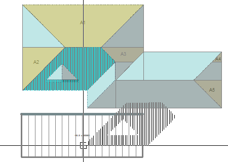
Select Define Block and select the first roof plane you wish to put a block on – Step 1.
Once you click on the plane the software asks you to locate any Block Edge Lines you want to Stretch. (This may be required if the automatically inserted block doesn’t extend into the area that you wish to apply the block to). This can be any of the lines you just need to stretch them one at a time.
 In this case this block is [OK] as it is, so right click [Cancel], and the Block will attach itself to your cursor and you can place it outside of the roof area ready for roof planes to be assigned to the block.
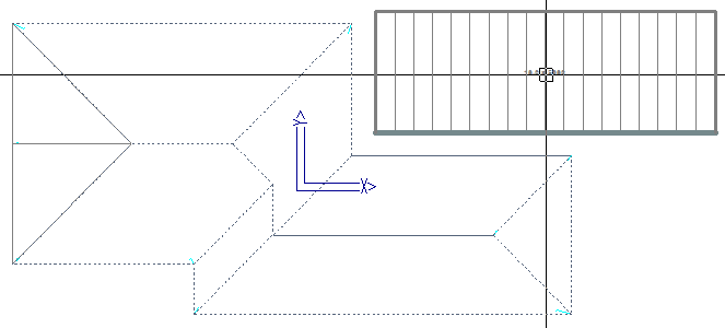
Step 2 – Place Block

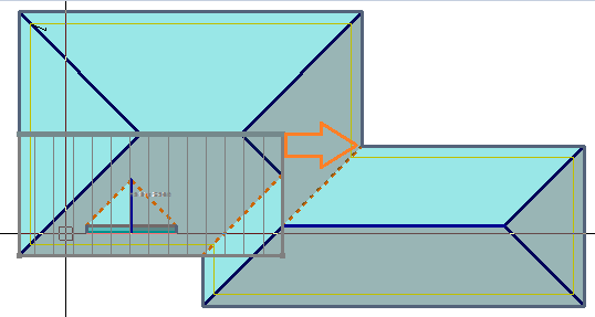
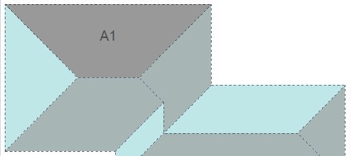
Next select Assign Roof Planes to Blocks and select the section of roof you want to be called A1.
 Rotate Plane/Change Snap Point
This will attach the roof plane to the cursor and you can use function keys F1 & F2 to rotate the plane and use F3 & F4 to select a point on the plane that makes it easy for you to attach it by ‘snapping’ to a point on the block outside the roof.
Alternate ‘snap points’ using F3 and F4 to conveniently snap to the corner of a block.
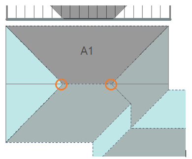
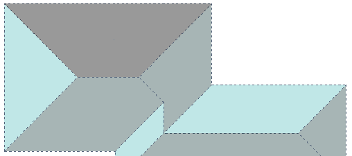
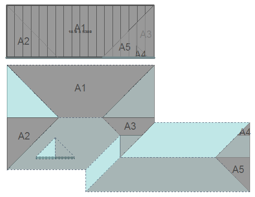
Step 3 – Assign Roof Planes to Block and Repeat until Complete
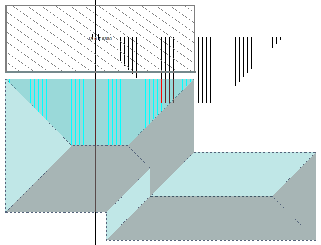
Middle mouse button, ‘Snap’ the roof plane to the corner of the block. Once attached to the block it will display as A1.
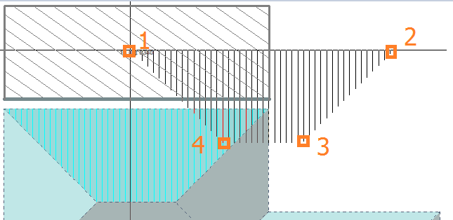
 To get the off cuts into the correct place right click to cancel from the Assign function, and select the Split Plane at Point command.
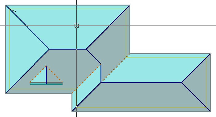
Using the far left plane as a starting example, select the roof plane to divide and then snap to the point at which you want to split the plane – in this instance it’s the apex of the two hip lines, you should now see a line that separates the 2 halves of the hip end triangle.
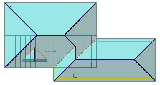
Select the opposite hip apex by snapping, and divide that roof plane as well.
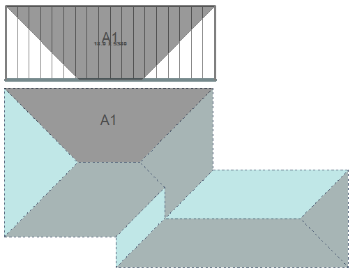
Now go back to Assign Roof Planes to Blocks and by selecting one side of the split line and using F1 or F2 to rotate the block-piece until it fits in place on our block taking note of the panel lay direction indicated by the hatch lines.
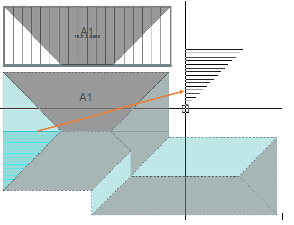
F1 or F2 to rotate into the correct orientation, then snap to the corner of the block. Note that the block-piece designation automatically increments to the next number ie A2.
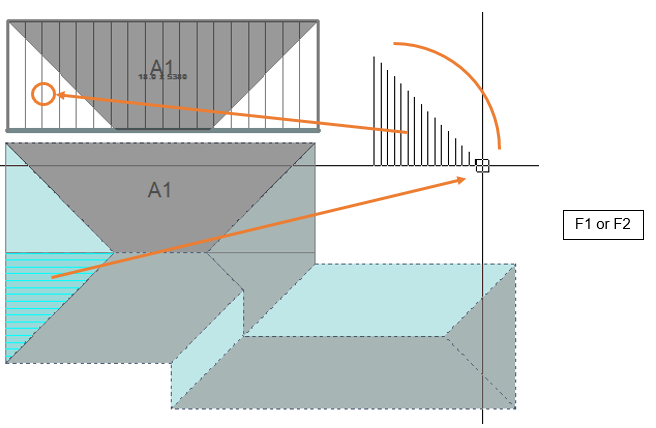
Repeat on the other side, finding the appropriate place for block-piece A3 by using rotate until that block-piece fits.
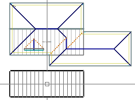
Split the hip end at the right using Split Plane at Point, so that two areas are created to reveal A4 and A5,
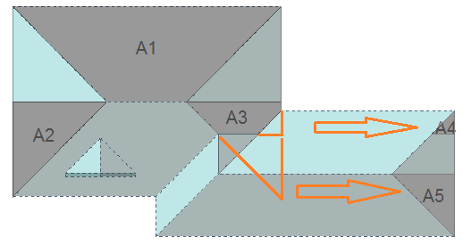
Now assign the 2 planes that were just created to Block A as A4 & A5.

Now that all of block A has been filled, we must define a new block which will be block B. Select the plane area that will define block B; select the right hand edge to stretch, and stretch the edge as shown, using the middle mouse button to snap to the corner.
Right click to cancel that operation (assuming that you stretched it correctly), and move the block to a spot outside the roof area so that block-pieces can be assigned to that block.
Once that is done and the Block-Cutting dialog box comes back up, click [>] at Block Letter to increment it to the next letter or R to reset it back to A, with Block Number Clicking [>] takes it to the next number or clicking R takes it back to 1. With Block Colour clicking > takes it to the next colour in the pallet or clicking […] lets you pick any colour in the colour table that you have set up.
Assign this block to be “B”
That gives us B1 & B2 which are obvious. Then split the planes as shown to give us B3 and then assign block-pieces B3 and B4 to the block. Next, move block-piece B5 onto our block.
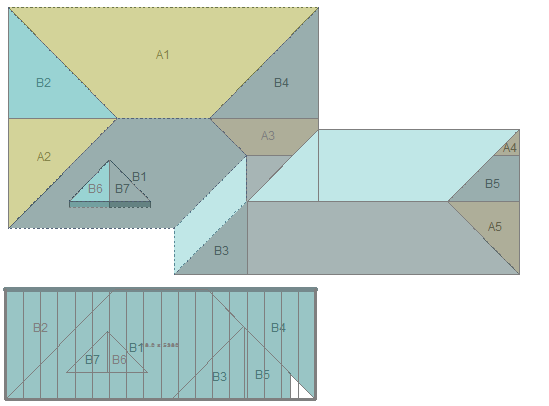
Split the planes on the dormers at the bottom of the valley. And Assign those as B6 and B7. Then move the block-pieces B6 & B7 onto our block B.
Then define a new block which will be labelled C.
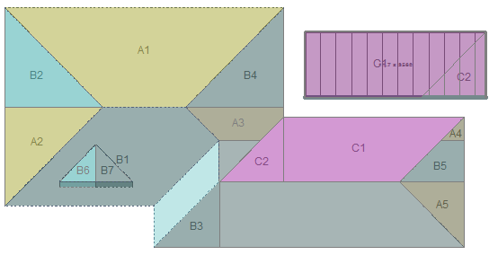
Continue this process for each subsequent block, splitting and assigning until they are all accounted for.
In the case of the small hip/valley (where E1 and E2 will be placed) don’t have a point to snap to, so scroll zoom in and select a point close as you can to the valley.
Select extend edge and then click on one of the block lines then snap to the top of D2 and B1 depending on which edge you started on and then repeat on the other side.
Stretch the edge back to the apex of the hip and ridge by snapping to the apex point. Then stretch the outer edge and snap to the geometry on the valley.
Can now move the block out and insert the remaining corners to create E1 and E2.
Note: If you have jumped in an out of the Block-Cutting dialog it is possible that the software has lost track of which block you’re trying to associate with which roof plane. Use the Cut Plane Option – Select Block before you select Assign Planes to Blocks to get yourself back on track.

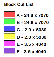
After all Blocks have been accounted for, you can use the function Place/Move Legend to annotate the Block-Cut drawing with the summary of the cutting list – for example:
Note that this shows fractions of sheets. This can be adjusted to round-up to whole numbers of sheets by changing the settings in Estimate > Allowances.
Then to finish it off 2 straight sheets for F1 & F2 on the front of the dormer.
Using Estimate > Tally-Blocks we see the correct cutting list and optimised for re-use of the waste – just 2.93%.
This method takes some adjusting to but after many years of using this exact same process manually, most roofers will find this interactive process for generating what they currently do with coloured pencils, a real bonus.
It shows the estimator that everything has been accounted for and the automated report is then available for the installers as well.
Block-Cutting Options
The block Letter, Number and Colour options set the designation that you will use to identify each block as they are associated with the respective roof planes.

They automatically increment, as each block-piece is applied to the block. The [>] button takes you to the next letter or number in the sequence; the [R] button resets to A or 0,
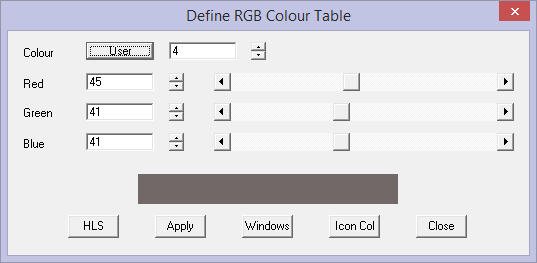
The block colour can be any of 256 colour numbers and any colour number can be any colour as defined under CAD > Defaults > Colour Table.
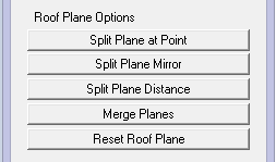
Block-Cutting > Roof Plane Options
Split Plane at Point
This function allows you to select a plane, in the example, the plane at the hip end (1), then middle button snap the apex of the ridge and hip for a point to split the plane through (2).
The hip end plane is split to form two block-piece planes that are available to use on the blocks as you create them.
Split Plane Mirror
There are other situations where you need a bunch of extra block-pieces defined on the roof. The command Split Plane Mirror will give you a mirror image of a split point on the same plane.
And the adjacent roof plane can be split in a similar manner to create block-pieces 3 and 4 using the same snap point.
Split Plane Distance
This function allows you to split a plane to create a block-piece of a specific distance from a reference point. Follow the prompts carefully as you must define the reference point, the distance from and the distance to the location of your split line.
In this example, we needed a split line 1200mm (~4’) from the apex point to create a block piece that suited how we intended to utilise the block pieces.
Merge Planes
This option allows you to remerge planes that you might have mistakenly split. Planes 1 and 2 will become one again.
Reset Roof Plane
Removes the annotations that might have been placed incorrectly and allows you to do it again with new annotation.
Now you see it, then you don’t.
Block-Cutting > Block Options
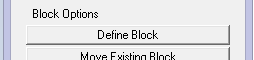
Define Block
This function automatically creates a block about the extents of the roof plane selected, then prompts to extend the block edge, if required. If the block is the correct size, then right click [Cancel] to place the block ready for placement of block-pieces.
Move Existing Block
Once a block is placed, you may decide to place it elsewhere to make room for new blocks around the roof model.
Modify Blocks
 This brings up the Modify Blocks toolkit that allows all manner of modifications to the automatically created blocks. These functions are well described in the previous section on Blocking (as distinct from Block-Cut). The key function specifically relevant to the Block-Cutting process is the option Show/Hide Block-Cutting which turns the block-cut outlines on and off.
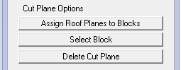
Block-Cutting > Cut Plane Options
Assign Planes to Blocks
Once you have created your blocks and split the roof planes into block-pieces, you then assign the block-pieces to the block.
You do this typically starting with the largest and most obvious block-piece and it will be annotated block-piece 1 – in this case block-piece A1. Then select the next block-piece to be placed and this will be annotated A2 etc.
As the block-pieces are selected, they may not be oriented to suit the placement onto the block, so use function keys F1 and F2 to rotate the block-piece. If the ‘snap-handle’ is not in the correct corner, use F3 and F4 to change the handle so you can middle mouse button ‘snap’ it to the block, repeating the process until all block-pieces are placed and that block is complete.
Select Block
If you have been moving around the model and changing blocks etc, you may need to re-select the block so that you can assign the block-pieces to the correct block.
Delete Cut Plane
This function deletes a cut plane that you might have created so that you can create a new one.
Place/Move legend
After all Blocks have been accounted for, you can use the function Place/Move Legend to annotate the Block-Cut drawing with the summary of the cutting list – for example:
Note that this example shows fractions of sheets. This can be adjusted to round up to whole numbers of sheets by changing the settings in Allowances.
Delete All Block-Cut Planes
Deletes all the cut planes so that you can start again. Sometimes you learn a more efficient way to do a job only after doing it a different way. Since this is so quick, don’t be afraid to try alternate ways to block and split planes.
Move Text
Moves the annotation text so it is easy to read.
Move Group
Allows you to move an entire block and all its block-pieces to a different part of the screen sothat the report is more easily read.
Undo
Undo the last operation.
Redo
Redo if you Undo too far or you decide that the Undo was actually correct.
Tools
This group of functions uses the same functions available elsewhere in the software, but puts them at your immediate disposal, saving time navigating to these often used functions.
Measure b/t 2 pts Uses the Tools > Measure function to establish the distance between two points in the model so you can calculate the split or the block.
Measure Length of Entity Uses the Tools > Measure function to measure the length of a line or roof plane edge.
Check Model Uses the Tools > Check > Check Model Integrity function to make sure that your changes to the model to accommodate the blocks etc have not messed up the model geometry.
Delete Free Lines Points Uses the Tools > Check function to delete redundent geometry in the model, keeping it clean.
Block-Cut Output
The Block-Cut template for MS Word creates the required report for your installers. The template for this is in the ..\User folder. Refer to Templates and Key Text Strings for more details.
VERY Important Note for the Block-Cut Method
Always pay attention to the placement of your block pieces. Consider how the installer is going to install the individual sheets and how they must then handle the offcut sheet.
What you must be aware of is that each sheet has an overlap and underlap side.

You must never place two underlap edges or overlap edges together on the layout – they cannot be installed this way. Consider the example below:

The placement of block piece B5 made for a very efficient use of material and they run the correct way up and down the roof, but when the sheet is flipped, we have two of the same laps together.

It cannot be installed this way, so you have to find another location for that piece, or change the layout of your blocks.
You will note that the complete block has a thin line along one edge, and a thicker line along the opposite edge.
Use this to guide you as to what pieces can go where when they are flipped into place.

This technique helps guide your installer how to install sheets in the most efficient way, re-using as many of the offcut sheets as is possible to reduce waste and hence reduce costs – but this only works if they are set out correctly.
The installer will also try to account for the prevailing weather, and start laying the sheets with this in mind.

This information is very rarely, if ever provided to you, and the installer will make the call when on site, so don’t stress about that consideration. Focus on getting all the laps the same direction when each piece in a block is flipped .
 Auto-Block-2
This method of blocking panels is a derivative of regular blocking of panels that simplifies the cutting list and the panel layout, but does require the field installers to understand the estimator’s intentions with the panel placement. You do not get the coloured placement drawings of the Block-Cut method although the theory of panel placement is derived in an identical way. However, it is fully automatic where Block-Cut is interative, requiring the user to control where blocks go and how they are split etc.
This has also been largely superceded by the ‘Block-Cut’ method of generating the cutting list.

Result using Auto-Block-2
Essentially it presumes that all triangle areas have a corresponding and matching off-cut triangle and when combined, create larger rectangular areas which become the ‘block’ areas. The benefit is a very quick and simple method of blocking the roof. It works for most roof geometry and not so well on others. If your crews know and understand this method, you will know that you’re using the correct estimating method for them. The calculation of the blocked areas is based upon the ridge lines. Each ridge line in the model is represented by 2 blocks that occur on either side of the ridge and extend as far as the roof geometry permits.
Compare this with regular Auto-Block shown below:

Result using Auto-Block
The waste factors for each may also vary depending on roof geometry. Experiment for your particular style of work for the best result for your business. In use the operator is prompted whether round the number of sheets in block. This rounds the number of panels/sheets up to a whole number as it goes instead of at the end. This may result in a few extra panels.

Select [OK] and the blocks are calculated. Then select Tally Blocks to generate your cut list.

The cutting list that is produced is the simplest of all cutting lists and is preferred by the manufacturers, but as stated above, your install crew must have the experience with using your result.
All the manual blocking tools may be used to adjust the result as for Auto-Block-1, but this would not normally be expected.
Generate Offcuts
(Pulldown Menu Only – Totally superceded by the Block-Cut method as it provides for greater flexibility of the output, thus better suited to the variety of options you find in practice.)
The Gen-Offcuts method of estimation utilises the off-cut created from hips and valleys and places it elsewhere on the roof, thus reducing wastage and optimizing the material required. Effectively it is ‘flip-flop’ing triangles of material, rather than rectangles of material as was used in the previous method of estimating we call Blocking.
This method is only feasible with certain profiles that maybe split and flipped etc. It is not practical for profiles such as standing seam for example. Gen-Offcuts has been largely superceded by the Block-Cut method, which provides for a better result for a greater number of different roof shapes. Gen-Offcuts really only suited to the simpler roof shapes.
Upon selecting Gen-Off-cuts as your estimation method you are prompted with the following dialog box:

The three options you have, relate to how you want your panels/sheets “Optimised”, if at all.
Do you want to Merge Jack-End Sub-Blocks?
By selecting NO it will not review the placement of Jack-End Sub-Blocks.
If you select YES, the software looks at each and every Jack-End Sub-Block (the triangle shaped block bounded by a hip and a valley) and determines whether that block can be accounted for with an adjacent triangle in the same roof plane – O8 and C8 in the example below.
Gen-Offcuts
The Gen-Offcuts method of estimation utilises the off-cut created from hips and valleys and places it elsewhere on the roof, thus reducing wastage and optimizing the material required. Effectively it is ‘flip-flop’ing triangles of material, rather than rectangles of material as was used in the previous method of estimating we call Blocking.
This method is only feasible with certain profiles that maybe split and flipped etc. It is not practical for profiles such as standing seam for example.
Upon selecting Gen-Offcuts as your estimation method you are prompted with the following dialog box:

The three options you have, relate to how you want your panels/sheets “Optimised”, if at all.
Do you want to Merge Jack-End Sub-Blocks?
By selecting NO it will not review the placement of Jack-End Sub-Blocks.
If you select YES, the software looks at each and every Jack-End Sub-Block (the triangle shaped block bounded by a hip and a valley) and determines whether that block can be accounted for with an adjacent triangle in the same roof plane – O8 and C8 in the example below.

Do you want to Modify the Length of Straight Blocks (Half)?
By selecting NO it will not reduce the number of panels/sheets in a block.
If you select YES, it will calculate the total length of the eave defining the length of the block(s) and divide it by the panel/sheet width. If this number is less than what has been calculated without reduction, it will use the smaller number of panels/sheets. This process only works when Rounding is turned on.
Effectively, what this function is doing is looking across the width of a run of eave, in case of the illustration below, the combined width of Block 1 and Block 2 and determining the number of panels/sheets required to cover the roof and compares that with the number determined by the number of panels/sheets in each block.
In the example, Block 1 would require 6.6 panels and Block 2 would require 5.3.panels. If each block is rounded then the total number of panels supplied would be 13 (7 panels in Block 1 plus 6 panels in Block 2). If it is accepted that rounding the whole run instead of each block would work for the job, select Yes, then you will supply 12 panels – the over supply of the longer panel in Block 1 will account for the under supply in Block 2 (7 panels in Block 1 and 5 panels in Block 2).

To the prompt – “Do you want to round the sheets in each block?”
Selecting NO, will treat each block of same length sheets in the whole job separately, and only round up once they have all been grouped together. e.g. 3.6 @ 3000, 2.2 @ 3000, will calculate 3.6 + 2.2 = 5.8 rounded to 6 sheets @ 3000mm. This is the smallest number of panels/sheets to cover the roof and the best result in the cut-list, but has no margin for error on site.
If you select YES, each block is rounded up before being grouped together. e.g. 3.6 @ 3000, 2.2 @ 3000, will be rounded up first to 4 @ 3000, 3 @ 3000 and calculate 4 + 3 = 7 sheets @ 3000mm. This is efficient and with maybe one or two spare panels/sheets in case of error on site
By clicking [OK], the off-cuts process will begin. Once the off-cuts have been generated, you are prompted with the following dialog box.

Often you get a lot of short sheets on roofs where a hip and valley are close together, and other areas of material that do not end up with a matching triangle of off-cuts. This prompt relates to the way they are nested together to further reduce waste.
Maximum sheet length:
This length then determines the order of the sequence. As you reduce the maximum length, the amount of waste increases. Also, pieces longer than the maximum length are not modified. The default length you are presented with is the one associated with that profile when you created it. If you enter zero (0), then the process ignores a maximum sheet length.
Nesting of narrow pieces:
Here you choose to either combine the narrow pieces into the nesting, or ignore them, and simply add them to the end of the coil.
Detailing of narrow pieces:
If you choose to add the narrow pieces to the end of the sequence you can nominate how you have them annotated. You can have them annotated collectively or individually.
By clicking [OK] the off-cuts are generated giving you your cut list, similar to the following.
By clicking [Continue], you can see how the job has been estimated by the software. As with the Blocking method of estimation there is provision to manually interact with the layout or lengths of sheets to reduce waste through having too much off-cut material.
As this example shows, waste was reduced from 12.4% to 8.3% of the material supplied. Other examples have produced savings of as much as 10 or 12% depending on the roof shape and the number of cuts.
Do you want to Turn Remaining Sub-Blocks into Strips?
By selecting NO it will not divide sub-clocks into individual roof sheets, instead just describing the area as a number sheets that will cover the area and it will not attempt to nest the panels into one or multiple lengths to reduce waste from off-cuts.
If you select YES, the areas that cannot be divided into triangular Off-cut Blocks, are then further divided into individual panels/sheets that are then nested using the linear nesting algorithm to reduce the waste from cut sheets as shown below.

There are 3 different categories for how the sheets are reported:
C/O – Cut sheet and related Off-cut, which are also grouped by colour – matched triangles of roof areas.
S – Straight sheet areas – rectangular blocks/Areas.
Sht – Single sheets, individual or nested sheets.

Once the Gen-OffCuts process is complete, the placement of sheets are shown on the off-cut layout drawing (shown above) and tallied on the accompanying sheet printout shown below. The 2 main drawings for the off-cut method are found under Reporting > Drawings and are called Off-cut Layout and Panel Cutting Details.

The top table is a summary of the individual sheets which may be nested, required for the job. The bottom table is a summary of the Cut/Off-cuts and Straight sheets/blocks.
Following is an example of the Panel Cutting Details drawing generated for the individual sheets in a nested group.

Do you want to Modify the Length of Straight Blocks (Half)?
By selecting NO it will not reduce the number of panels/sheets in a block.
If you select YES, it will calculate the total length of the eave defining the length of the block(s) and divide it by the panel/sheet width. If this number is less than what has been calculated without reduction, it will use the smaller number of panels/sheets. This process only works when Rounding is turned on.
Effectively, what this function is doing is looking across the width of a run of eave, in case of the illustration below, the combined width of Block 1 and Block 2 and determining the number of panels/sheets required to cover the roof and compares that with the number determined by the number of panels/sheets in each block.
In the example, Block 1 would require 6.6 panels and Block 2 would require 5.3.panels. If each block is rounded then the total number of panels supplied would be 13 (7 panels in Block 1 plus 6 panels in Block 2). If it is accepted that rounding the whole run instead of each block would work for the job, select Yes, then you will supply 12 panels – the over supply of the longer panel in Block 1 will account for the under supply in Block 2 (7 panels in Block 1 and 5 panels in Block 2).

To the prompt – “Do you want to round the sheets in each block?” Selecting NO, will treat each block of same length sheets in the whole job separately, and only round up once they have all been grouped together. e.g. 3.6 @ 3000, 2.2 @ 3000, will calculate 3.6 + 2.2 = 5.8 rounded to 6 sheets @ 3000mm. This is the smallest number of panels/sheets to cover the roof and the best result in the cut-list, but has no margin for error on site.
If you select YES, each block is rounded up before being grouped together. e.g. 3.6 @ 3000, 2.2 @ 3000, will be rounded up first to 4 @ 3000, 3 @ 3000 and calculate 4 + 3 = 7 sheets @ 3000mm. This is efficient and with maybe one or two spare panels/sheets in case of error on site
By clicking [OK], the off-cuts process will begin. Once the off-cuts have been generated, you are prompted with the following dialog box.

Often you get a lot of short sheets on roofs where a hip and valley are close together, and other areas of material that do not end up with a matching triangle of off-cuts. This prompt relates to the way they are nested together to further reduce waste.
Maximum sheet length:
This length then determines the order of the sequence. As you reduce the maximum length, the amount of waste increases. Also, pieces longer than the maximum length are not modified. The default length you are presented with is the one associated with that profile when you created it. If you enter zero (0), then the process ignores a maximum sheet length.
Nesting of narrow pieces:
Here you choose to either combine the narrow pieces into the nesting, or ignore them, and simply add them to the end of the coil.
Detailing of narrow pieces:
If you choose to add the narrow pieces to the end of the sequence you can nominate how you have them annotated. You can have them annotated collectively or individually.
By clicking [OK] the off-cuts are generated giving you your cut list, similar to the following.
By clicking [Continue], you can see how the job has been estimated by the software. As with the Blocking method of estimation there is provision to manually interact with the layout or lengths of sheets to reduce waste through having too much off-cut material.
As this example shows, waste was reduced from 12.4% to 8.3% of the material supplied. Other examples have produced savings of as much as 10 or 12% depending on the roof shape and the number of cuts.
Do you want to Turn Remaining Sub-Blocks into Strips?
By selecting NO it will not divide sub-clocks into individual roof sheets, instead just describing the area as a number sheets that will cover the area and it will not attempt to nest the panels into one or multiple lengths to reduce waste from off-cuts.
If you select YES, the areas that cannot be divided into triangular Off-cut Blocks, are then further divided into individual panels/sheets that are then nested using the linear nesting algorithm to reduce the waste from cut sheets as shown below.

There are 3 different categories for how the sheets are reported:
C/O – Cut sheet and related Off-cut, which are also grouped by colour – matched triangles of roof areas.
S – Straight sheet areas – rectangular blocks/Areas.
Sht – Single sheets, individual or nested sheets.

Once the Gen-OffCuts process is complete, the placement of sheets are shown on the off-cut layout drawing (shown above) and tallied on the accompanying sheet printout shown below. The 2 main drawings for the off-cut method are found under Reporting > Drawings and are called Off-cut Layout and Panel Cutting Details.

The top table is a summary of the individual sheets which may be nested, required for the job. The bottom table is a summary of the Cut/Off-cuts and Straight sheets/blocks.
Following is an example of the Panel Cutting Details drawing generated for the individual sheets in a nested group.

Modify Offcuts
 Modify Offcuts provides tools that permit viewing and liited changing the Off-cut Layout generated automatically.
Verify-Combo highlights the matched pair of triangular areas of panels that will make up a cut/off-cut area.
Delete-Combo deletes a combined cut/off-cut pair from the job.
Merge-Off-cuts merges a selected panel/sheet with an adjoining group of cut/off-cut triangular areas. The panel/sheets as shown below can be merged with the adjoining area.
Sht-12 can be merged with C11; S5 with O4 and S6 with O3 etc. around the entire job.

On this side of the roof, the following panels/sheets can be merged without effecting the job and reducing waste from off-cuts.

Removing the Sht-12 (0.18 of a sheet width) and merging it with C11 and this area goes from 5.51 of a sheet width to 5.69 of a sheet width – enough material to cover the job, without adding an extra panel/sheet.

The installers can see at a glance, where all the material is to be installed.
Delete-Sheet allows the operator to delete an individual panel from the cut list. This would be done if it was clear that an off-cut strip from another area of roof could be used instead.
Change-Length allows the operator to change the length of a cut/off-cut combination.
Change-Sheets allows the operator to change the total number of sheets in the job by adding or subtracting from the sheet count.
Tally Offcut Panels
This command generates the cut list for the optimized panels and reports total number of panels, and the total length of coil required, just like the previous methods. It must be run before a cut-list is created or costs can be determined under Reporting.
Del Offcuts
This command simply deletes the off-cut areas from the model.
![]()
Note for when you are setting up your report templates: Use the key text string ###SheetList to display the panel lengths in a table on the report.
If the text that annotates the panel areas appears to be too small on the Microsoft Word report, that is not a problem with the template, it will be the plot scale of the roof before you print. The trick is to set the plot scale so that the text is legible on screen, then generate the report.
 Generate Panels
(Pulldown Menu – Estimate (Metal) Only)

The Gen-Panels command automatically draws individual metal panels on every metal roof plane in the model.
If you have not yet set the roof cover material with the Cover Roofing command, you will be prompted to do so. After that the metal panels are generated.
The actual line you see on the roof plane is the line you see on the roof. The following diagram illustrates the lap direction
The lap direction is used when generating the panels. The starting point for the layout is determined by the longest gable line on the roof plane, the lap direction and the panel underlap distance. If there is no gable on the roof plane, the starting point will be the end as determined by the lap direction.
The following diagram shows a full hip roof and the metal panels.

The following diagram shows how gables on a roof plane can reposition the starting point of the layout. In the case of a dutch-gable feature, the full width sheet starts at the gable.

Gen One Plane
(Pulldown Menu – Estimate (Metal) Only) > Generate Panel Layout > Generate One Panel)
This function generates panels precisely the same as described above, but one plane at a time.
 Set Panels
These are a series of commands that allow you to set up the lay of the panels on the roof and the panel offsets according to settings defined in the Allowances.


Ins-Lap-Dir
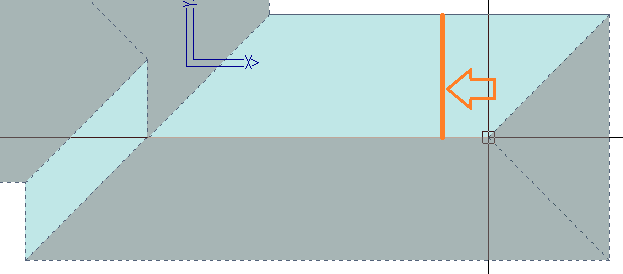
This command lets you draw an arrow on the model which defines the lap direction for the Gen-Panels-One command and the Gen-Panels-All command. If not selected, the software automatically determines the lap direction with the priority being laying away from a gable end on the roof.
The lap direction defines the overlap side of the sheet, and consequently will alter how the panel sequence is generated in the Linear-Nesting command.
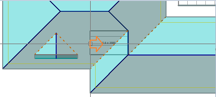
The following diagram shows the insertion of a single lap direction:

You will see that d3 defines the direction of the arrow as left or right (compared to d2).
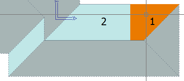
The following diagram shows you the effect of the lap direction with respect to the underlap.
For a good result using linear nesting, it is necessary that consecutive roof planes have opposite lap directions.

Ins-Lap-Dir-Auto
This command automatically draws lap direction arrows on the model which defines the lap direction for the Gen-Panels-One command and the Gen-Panels-All command. In effect, the lap direction defines the underlap side of each panel.
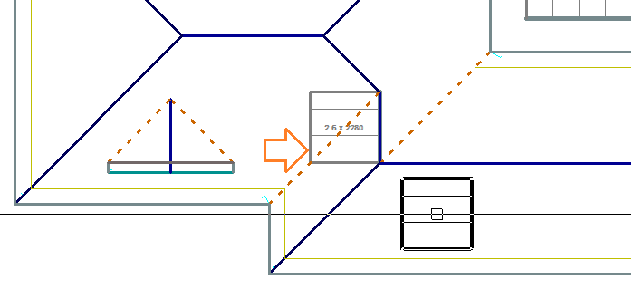
The following diagram shows the lap direction arrows automatically inserted onto the model

You will notice on the above diagram, that some optimisation of lap direction occurs. You will see at each hip end, that there is one lap direction going away and one going into the hip. Also, around each hip end, the directions are not the same in subsequent sides. However, you will notice that the directions are the same for the bottom and right hand roof planes. You can change this using the next command.
Swap-Lap-Dir
This command lets you swap the direction of a lap arrow if you want to change the direction to account for the visual appeal of the roof or perhaps to account for prevailing weather.
The following diagram shows 3 lap directions changed. As a rule of thumb you get a better nesting result with linear nesting if the lap direction on consecutive roof planes is opposite.

Swap-Lap-Dir-Win
This command does the same as the previous command, but lets you select the lap direction arrows using a window or by selecting more than one at a time.
Del-Lap-Dir
This command lets you delete a lap direction arrow.
Offset roof
This command automatically creates an off-set roof given the clearance values and the batten thickness you set in the Estimate Allowances dialog box. This defines the geometry of the panels as distinct from the geometry of the roof, which are not usually the same. When roof panels/sheets are next generated using Gen-Panels, they are generated to this geometry, not the roof geometry.


Change-Offset
This command allows you to manually change the offset on each line at a time. By selecting on the roof plane to change the offset on, you are prompted with the following dialog box.

Simply enter in the new offset and click [OK]. The new offset will then be applied to that line. This helps to make minor adjustments to the offset plane which effectively adjusts the sheet lengths following verification of field measurements of the roof to be covered.
Del-Offset
This command deletes the offset roof planes created by Offset-Roof.
Set-Section
The Set Section function allows you to name a group of planes that will be tallied and drawn together, thus simplifying ordering, delivery and installation, especially on very large projects.

Then when you you set the sequence, it is clear which area is associated with what and the sequence can be set.

Set-Sequence
This command lets you sequence the numbering of the roof planes for the Tally-Panels and Linear-Nesting commands. You do not have to define the sequence as Roof Wizard will do it for you. Here you have the opportunity to change the sequence. When you select Set-Sequence, the sequence numbers of each roof plane are displayed.

The initial numbering of the roof planes is based on the order of the roof planes in the Roof Wizard database. In the above drawing, you may want plane 11 to be number 1, then go clockwise around the roof.
To change the sequence, you first click 11. This then becomes 1 and what was 1 is now 11. Then you click 10. This becomes 2, and what was 2 now becomes 10. You then proceed around the roof in the order you wish the roof planes to be covered.
To finish assigning the sequence, click the abort button. The sequence numbers then disappear. To see the sequence again, click Set-Sequence.
The Tally-Panels command and the Linear-nesting command use this sequence to number the panels on each of the roof planes.
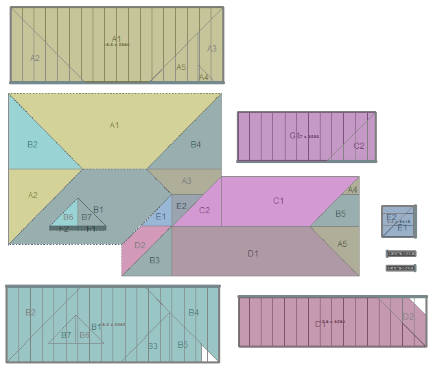
This is also used in producing the drawing called the Section Report. This shows each area of roof panels as a separate drawing. (Refer to report templates and key text strings for ###RoofSectionDrawing and ###SectionReport).

An example of a full section report may be downloaded here along with the usual roof quotation details report here. This is an extremely helpful report for your customers, especially the installers, as it helps them understand how you want the job completed, right down to how each of the long panels are to be cut to create the short panels as shown below.

An example Section Report template has been provided for your use. Feel free to download this, save it to your user folder, edit the UserReportNames.csv file to add it to your available list and try it for yourself.
 Modify-Panels
This command brings up another menu with several options for modifying and annotating the panels.

Realign-Panel
This command automatically draws individual sheets on a selected roof plane in the model. You would use this command to change the starting point of the sheets on a plane.
After you select the command you are prompted to select the plane you want to generate the sheets on. Then you locate a point through which you want a sheet edge to go.
After you have located the point, the sheet alignment is updated to suit.
The following diagram shows the selection of a plane (d1) then snapping to the hip apex (d2). This forces the seam to go through the ridge apex point.

Split-Panels
This command lets you split metal panels on a roof based on maximum length of the panels or by the positions of battens on the roof.

The dialog box displays parameters for standard panels and the splitting methods you can use.
Overlap – Bottom of Panel sets the amount added to the sheet for lap. It is, in actual practice half this amount as it is calculated about the centre line of the purlin or batten.
Underlap – Top of Panel is the amount added to each panel at the top of the panel and this is also calculated about the centre line of the purlin or batten.
If the base of the panel is at the eave, then the eave overhang value is added to that panel length.
The panel parameters of “Eave overhang” are set under the Gen-Panels > Allowances option.

Splitting Methods
Specify/Use the maximum panel/stock length
This method will use the maximum panel length you defined for this panel to split the panels in the roof or the number you specify when prompted –

The length starts at the base of the panel. You can modify which panels are split by selecting an option under “Apply split to”. Here you can limit the splitting to a single roof plane or a single panel rather than splitting all panels on the roof.
Note – If a selected panel definition has a ‘Stock Length’ table defined, such as one would have with a long run metal tile profile which has a repeating pattern of say 300mm or 500mm, then the appropriate stock length will be selected.

However, for this to calculate and display correctly, the allowances must be set to round off using the [Round-Off Panels to Next (mm)] setting for the profile selected, and also set the annotation to rounded panel length [(Rnd) Panel length Only] or you will not get the correct cutting list or correctly annotated panel layout you would send to site.

Once set, the cutting list reflects the material selected and the way it is to be supplied.

Note also that if you the setting [Combine for Maximum Lengths] , then the cutting list is optimised for this purpose, making it easier to pack and ship the job.
Select the batten up to the maximum length
This method lets you select the batten to split the panels. In this case, you need to select the batten for each roof plane.
Auto select the batten up to the maximum panel length
For this method the split position will be at the intersection of a roof batten which falls short of the maximum panel length. (You must have inserted battens using Cover > Battens for this method to work). Again, you can modify which panels are split by selecting the relevant “Apply split to” field.
Insert a new panel between battens (Roof Lights)
This method lets you insert a new panel between battens and adjust the lengths of the adjoining panels to suit. You would have already split the initial panels at a batten before carrying out this command. After selecting the new panel to insert, you then select the 2 battens between which the new panel will be inserted. You then select pairs of panels, each on the same run which will be trimmed back to squeeze in the new panel.
Merge-Panels
This command allows you to merge two panels together. You can either merge two panels butting into each other to make a longer panel or two adjacent panels to make a wider panel
Change-Panel-Typ
This command allows you to change the material for individual panels. By selecting this command the roof metal panel dialog appears. Simply click the change button, select the new material and click [OK]. Crosshairs will appear and the panels will become highlighted. Simply select the panels that you would like to change, right click the mouse and confirm the entities. You will need to Tally the panels for the changes to be calculated.
Change-Panel-Len
This command allows the operator to change the calculated length of an individual panel, or group of panels by adding or subtracting and amount to or from the calculated length. This function allows for the panel length(s) to be adjusted subsequent to a site check-measure, without remodelling the entire job.
Select the panels to add/subtract an amount to; confirm selection.

Then specify the amount to add or subtract. A [+] sign adds to the calculated length, a [–] sign subtracts from the calculated length.

This will subtract 50mm from the calculated length.
Delete-Panels
This command allows you delete singular panels manually or every panel shorter than a specified length. By selecting this command the following dialog will appear.

By setting a number in the Select Sheets Shorter than field, then clicking Delete, any panels shorter than this length will be deleted automatically. By clicking on the Delete Sheets Manually, crosshairs will appear and all of the panels will be shown, simply click on the panels to delete. When you have selected all of the required panels, right click the mouse and confirm the entities.
Renumber-Panels
This command will automatically re-number all of the panels for you.
Show-All-Panels
This command will highlight all of the panels.


Move-Text
Should the location of the annotation still be difficult to read, a function exists to move the annotation and the leader line repositioned to suit. Select the option Move-Text and the prompts guide you through selecting, moving and moving the text and reposition the leader line. If you move the text, the software remembers where you move it to when the panels are ‘re-tallied’, unless the text is deleted.
Add-Del-Leader
This button also provides for deleting or adding a leader line to a panel annotation.
Add-Panel-Angles
For the correct installation of insulated metal panels, the installer will usually cut the panels to match the geometry of the roof, taking account of the thickness of the panel. This will also apply to structural insulated panels.
When we model the roof geometry in Roof Wizard, we make an assumption that, notionally at least, the panels have no thickness, so the geometry of the roof is not actually the geometry of the panels. Adding batten/purlin offsets as described above allows us to account for the panel thickness as well as or indeed, instead of purlin thickness thus defining the thcikness of the panels, and represented as shown below:
Now that we have the panel surface raised to the actual panel surface height (and added overhang into the gutter if required) we can now see that we are correctly representing the true panel size. Before we can install the panels, the installer must cut the panel edges so that opposite panels at the ridges, hips and valleys fit together perfectly.
To set the correct cutting angles for the saw, we need to advise the installer what these angles are as it is not a simple calculation.
Select the option Add-Panel-Angles, select a panel that is representative of the other panels on that side of the roof and insert all the details required to make the cut.

The software will correctly show the compound angle across each panel as well as the angle through the panel. As all installers know too well, the ridge and hip cuts are different.
It will display this for all edges that are cut, including roofs with multiplte pitches as shown above.


Simply select one panel that represents the panels to be installed on that side of the roof and the details for each panel cut, at the top edge and the bottom edge are displayed.

If a leader line is required, simply use the CAD > Line > Insert > Free option.
It is recommended that this function be used in conjunction with the Linear Nesting report function which shows the finished cut length of each and every panel on a job.
Del-Panel-Angles
Deletes the panel angle text.
 Tally-Panels
This command creates a panel/sheet list from the panels in the model. It will display up to 4 different materials, totalling 5000 different panel lengths. First, each panel is given a unique identifier which is derived as a combination of a roof plane number and a sheet number. The numbering is done in the lap direction.
After the sheets are gathered, the sheet cutting list summary dialog box is displayed, showing the number of sheets of each length, adjusted (if specified under allowances) for the rounding factor – in this case to the nearest 5mm. Note that the total length of coil required from inventory is also displayed, the total panel area compared with the total roof area with panels on it which gives you a waste amount as a percentage. You may set up various panel allowance files for different types of panel and these may be saved for later use. The allowance file in use is displayed for your information – in this case we used the [default] allowance file.

[Export To Rollformer]
The cutting list maybe exported in a file format for specific roll forming machines:

Select the required roll former controller format and select [OK]. The cutting list is instantly written and available to be sent with your job information.

The cutlist can be exported to the roll-former and can be grouped by section (as per Sections from Section Reports) or by storey, or no grouping.
The following controllers are currently supported:
- AMS Eclipse Controller
- Beck Automation Controller (not all models)
- Proface Controller
- New Tech Machinery 200 Controller
- New Tech Machinery 100 Controller
- New Tech Machinery UNIQ CS controller
- AppliCAD Standard Rollformer Output
Note that not all controllers have the ability to import a cutting list file. They are usually shared via a USB memory stick or a network cable – check with your machine supplier to ensure that you can take advantage of this function.
[Export CSV]
The Export Panel Lengths option in the software from the Tally-Panels menu allows the user to specify whether the output to a CSV should be split by Storey.
The default value for “Combine Storeys” is set to “Yes”, setting the value to “No” will split the panel length output by storey.
How The List is Determined

The drop down list shows the definition of the panel. To see the cutting list for other panel materials you have defined in the job, select their name from the drop down list.
You can also Delete or Change your panels here if required instead of going into Modify-Panels.
The roof panels are displayed highlighting any gaps or errors. It will also show the roof panels/sheets for the different materials that you may have selected for the roof. For example, if you have inserted translucent roof panels then they will be displayed separately from the rest of the roof panels/sheets. The illustrations below demonstrate how this is displayed.

The Sheet Allowances Used shows the allowance file selected by the operator and used for this roof system.


If you want to export this sheet list to a comma separated value file (.csv) for import into another computer system, click ExportCSV. Short panel lengths (shorter than the minimum sheet length) are added together to form longer sheets (but not longer than the maximum). If the last sheet is shorter than the minimum, then it reports as the minimum.
![]()
Remember : this method assumes that off-cuts will not be used. The panel/sheet length reported is therefore the maximum length of each panel/sheet, long point to long point. To reduce waste from Gen-Panels, use the Linear Nesting function described below.
Minimum Panel Length Breakdown shows the make-up of all the shorter lengths and how they have been incorporated into one length as shown below. The minimum panel length is set when the panel is defined (refer to the section on defining metal panels).

Section Report
A new report process has been created called the Section Report. This provides for a summary of all panels on the roof, plane by plane, with precise details for every panel on each plane.
The first step is to set the plane section ID and section sequence as described above and is used in setting the install sequence when producing the drawing called the Section Report. This shows each area of roof panels as a separate drawing. (Refer to report templates and key text strings for ###RoofSectionDrawing and ###SectionReport).
An example of a full section report may be downloaded here along with the usual roof quotation details report here. This is an extremely helpful report for your customers, especially the installers, as it helps them understand how you want the job completed, right down to how each of the long panels are to be cut to create the short panels as shown below.
To reduce the number of short panels in the pack to be shipped, you should set the minimum panel length when defining your panel profile (Set Up > Metal Panels). This may then be applied automatically for each panel by setting the switch in the allowances for that panel profile. The key switch is the one that sets [Apply Minimum Panel Length] and then you decide the basis for combining short panels into longer ones [Combine Min. Len. Panels].

An example Section Report template has been provided for your use. Feel free to download this, save it to your user folder, edit the UserReportNames.csv file to add it to your available list and try it for yourself.
 Linear Nesting
This process takes all panels from the roof, orients them with respect to lap direction and sequentially adds them together to form a single, continuous length of coil material. From the panel sequence list, individual panels are derived which form the basis of the cutting list.
After you confirm that you want to nest the sheets, the Linear Nesting defaults dialog box is displayed.
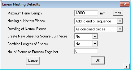
Maximum sheet length This length then determines the order of the sequence. As you reduce the maximum length, the amount of waste increases. Also, pieces longer than the maximum length are not modified. The default length you are presented with is the one associated with that profile when you created it (see Set-Up > Metal-Panels). If you enter zero (0), then the process ignores a maximum sheet length. If you set the length to be very small, then you get a result similar to Tally-Panels. Note however, that Tally-Panels does not take overlap into account.
Max. This button permits the longest sheet to be calculated by the software from the roof model and displayed for the user. This will help determine the optimum maximum panel length for the job.
Nesting of narrow pieces Here you choose to either combine the narrow pieces into the nesting or ignore them, and simply add them to the end of the coil.
Detailing of narrow pieces If you choose to add the narrow pieces to the end of the sequence, you can nominate how you have them annotated. You can have them annotated collectively or individually.
Create New Sheet for Square Cut Pieces This option provides controls for bundling panels into more manageable packs and may be used in conjunction with the following option.
Combine Lengths of Sheets This option provides controls for bundling panels into more manageable packs.
No. of Planes to Process Together forces the software to nest within a range of adjacent planes. This reduces the opportunity for the software to nest a piece from the opposite side of a roof requiring the installer to carry it across the job.
The following diagram shows you the end of the sequence and the narrow pieces simply added to the end.
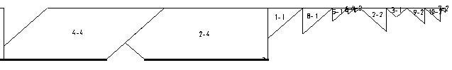
If you incorporate the narrow pieces in the nesting process, then you get a result similar to that below.
![]()
If annotated collectively, you get the following result.
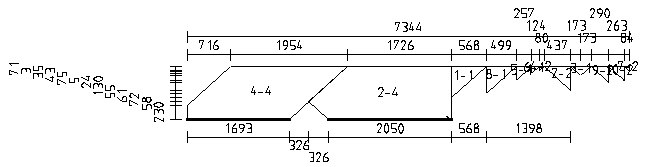
If annotated separately, you get the following –
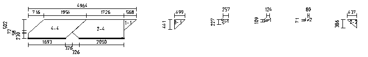
During the process, you see the generation of the panel sequence diagram and the panel detail diagrams. After the process these diagrams are saved in their own files and the dimensions that have been automatically inserted may be moved to tidy up the appearance of the output.
You can see the panel sequence diagram in the model called RW-Sheet-Sequence in the same database as the roof model. The entire panel sequence is automatically broken into smaller strips ready for it to be printed on A4 and letter size landscape format at a scale of 1:100. The entire sequence may also span multiple pages.
You can see the panel cutting diagrams in the model RW-Sheet-Cutting in the same database as the roof model. The individual panels are automatically positioned to fit on A4 and letter size, drawing at a scale of 1:100.
As part of the process, a PCF (Piece Coordinate File) is written detailing the coordinate perimeter of each piece on each sheet. Refer to the appendix for the format of the piece coordinate file. The actual name of the PCF file is <databasename>.PCF
Linear Nesting is performed by the software by calculation of how sheet cuts can be optimised using the seam/lap side. To define seam/lap sides in the software, you do this by inserting lap direction arrows. These arrows can be modified by simply selecting the Swap-Lap-Direction button and then clicking on the arrows that define the lap direction. Once inserted, the software will then nest the sheets according to these seam/lap direction arrows. If no lap direction is defined, the software simply takes each panel and places it into the nesting schedule, but does not allow for any rotation of sheets as it does not know which side the seam is on. As a result, very little successful nesting will occur compared to what would normally be expected.
If the lap directions are inserted in the way in which a roofer would normally lay out a roof, then the linear nesting will be much more successful, because the lay directions on a simple hip configuration, for example, will result in almost zero waste, when compared to laying out the roof in a haphazard manner.
The following diagram shows the annotation of the metal panels on the roof.
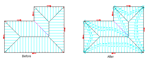
The panel sequence drawing is pre-processed to fit on A4 and letter size reports.
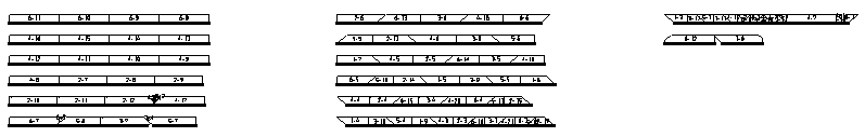
A close up of one page shows the annotation and sequence of the panels more clearly.
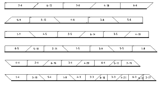
The cutting details are also preprocessed to fit on A4 and letter size reports.
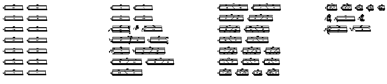
An enlargement of one page shows the annotations and dimensions for the nested sheets.
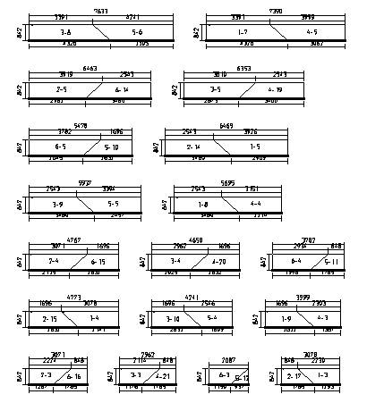
The cutting list sequence is modified by selecting those sheets with the minimum sequence number.
Gen-Panels ‘Show’ Options
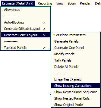
These options (available only from the Pulldown menu) allow the operator to review the Nesting Calculations, the nested Panel Sequence and the nested Panel Cut drawings without losing the model.
Once you are satisfied with the output displayed, select Show Original Model to bring the job back with the panels drawn according to the definitions used. These reports may be printed from the Reporting > Print Drawings menu.
 Delete Panels
Deletes the panel layout and also prompts for the removal of the lay direction arrows too.
Export to Rollformer
This button is at the bottom of all the Panel Cutting List Summary dialog boxes and provides for the generated cutting list to be exported to a text file for transfer via your network or memory stick to the controller of the machine.

Select the Export to Rollformer button and the dialog pops up that allows you to select the required output format.


The options are:
AMS Controls (Eclipse) – the proprietary format for the AMS Eclipse controller
Beck Automation – the proprietary format for Beck Automation controllers
Pro-face Controller – the proprietary format of Pro-face Automation PLC controllers
New Tech Machinery UNIQ CS Controller – the proprietary format of the NewTechUNIQ CS Controller
New Tech Machinery 200 Controller – the proprietary format of the NewTech NTM 200 controller
New Tech Machinery 100 Controller – the proprietary format of the NewTech NTM 100 controller
AppliCad PCF Output – the AppliCad proprietary format that describes the complete cutting details including the shape of each panel. For more details go here.
You are prompted for the required file name and the ellipsis button […] allows you to set the desired path for saving the file.
Select [OK] and the file is written.
Inserting Roof Lights/Skylights
This is the process for adding an alternate material to a metal roof, typically to install polycarbonate roof lights or skylights. The first step is to define your roof panels and purlins or battens. This is because you cannot have rooflights installed without a purlin to attach them to, especially if they are not full length panels. In this illustration, we will use a relatively small roof as our example for ease of use.
First model your roof and apply the selected roof panels – Cover > Select Panel.

Then apply purlins/battens to the roof – Cover >Flashing > Purlins/Battens.

Next we need to identify which panels will be switched out for polycarbonate rooflights.

You may have roof lights that run the full length, or you might be splitting them at a purlin/batten.
If you are simply switching the panels out, go to Cover > One Panel, the Panel Material dialog box is displayed, select the [Change Metal] button,

then select the polycarbonate panel you need.
![]() NOTE: the polycarbonate MUST be the same width profile for this to work.
NOTE: the polycarbonate MUST be the same width profile for this to work.
Now select [OK] and then select the existing panels that you want to become the alternate panel material, in this case, polycarbonate. As each panel is selected, it is highlighted as shown above. When you have finished selecting the panels to change, right click to cancel selection and you’re done.
Once complete, when you display the tally panel list, you get two lists under the heading of Material – the list of the primary panel, and the list of the alternate panel with the tallied panels listed highlighted confirming what you have done.


Roof Lights in Split Panels
If you are only switching out partial panels similar to this roof below,

then first you need to split the panels – use the Estimate > Modify Panels > Split Panels function to split the panels.

The panels are typically split at a purlin to provide a method of attaching the join to the structure. In so doing, the program will account for the lap between the two panels, so set this variable first [1].
Then we select the option to select each panel to split [2]. The panels have been laid on the roof at full length, we need to split them – we can split all of them or select individual panels to split. We will split individual panels in this example. Next we need to select the method of splitting – we will select the purlin line to split along, so select that option [3].

You will be prompted to select the line to split at [1], then you will be prompted to select the panels to split [2].

Once you have finished selecting the panels, right click and the panels will be split and a line indicating the split will be drawn so you can see that you have done it correctly. If you mess it up, simply select [Undo] and redo the same steps.
Often the panels are in the middle of the roof, so you need to further split the panels again by redoing the same steps but this time selecting a lower purlin [1], then the panels to split [2] – obviously, selecting the lower part of the same panels again.

The split line is drawn and you know that you’re OK. Note that you can select a full length panel at this time and split just the bottom half. These steps allow you to make any combination of short and long panels with a variety of materials on the same roof – provided they are all the same cover width.

You can see that you have done it correctly when the selected panels are highlighted.
Your cutting list now displays the list for the entire job.

Tapered Panels
(Pulldown Menu Only)
The Tapered Metal Panels function is only available from the Pulldown menu. It is used to create a cutting list for tapered standing seam panels automatically. The panels will be bound by an outline comprising at least one arc and may be pitched up or down.
Selecting the option Estimate > Tapered panels > Generate presents the following dialog box.

Arc Length Displays the actual length of the defining arc. The arc may be the high point or the low point of the geometry, but is usually the edge that defines the widest edge of each panel.
Panel Width Max. The width of the widest part of the panel.
Storey This sets the pay scale to use for the installation.
Num. Panels Displays the number of panels that will fit along that arc. This would typically be modified to a whole number of panels.
Pitch The pitch or slope up or down from the defining arc.
Pitch Direction Either up or down from the defining arc.
Eave height The eave or gutter height of the defining arc.
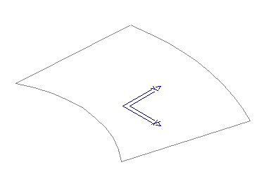
Defining the Geometry
Prior to generating any Tapered Panel roofing panels, you need to define the geometry that is used to place the panels upon. The geometry can be created as a 2D outline or profile, while the panels will be drawn accurately in 3D up the slope as defined by the pitch. The reasoning for this is that the geometry is generally provided from an architectural CAD model and is more often than not provided in 2D and may be imported directly into the workspace.
You may also draw the outline by using the tools provided in AppliCad. Typically use the CAD > Arc > Insert and CAD > Line > Insert functions.
Creating the Panels
Once the geometry has been created, define the Tapered Panels using the Estimate -> Tapered-Panels -> Generate command. Select the Roof Material to use. Typically this will be a standing seam profile previously defined under Set-Up > Metal Panels.
Locate the arc defining the tapered panel layout, near the lay start end. The panels are generated from that end. The dialog box for the roof parameters is displayed.
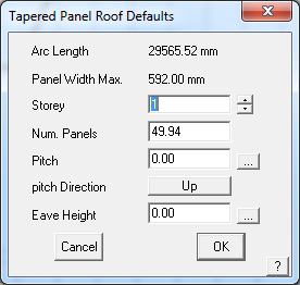
Once modified, the operator is then asked to identify the entities that constrain the panels. These are essentially the remaining entities in defining the panel extents and should be located in order:
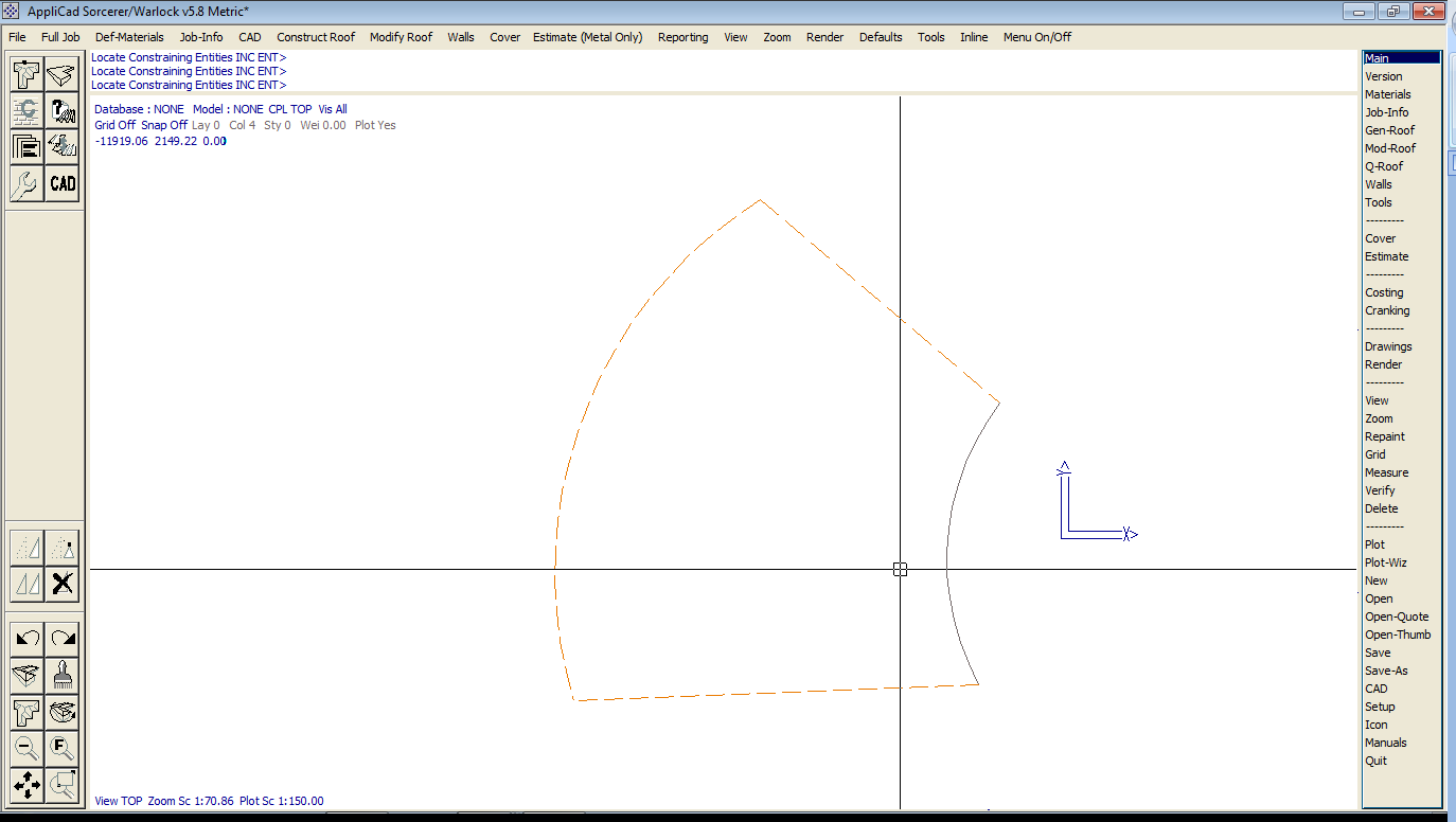
Once the constraining entities have been defined, the panels are drawn according to the constraining shape and the information specified in the previous dialog. An example of panels being drawn on our constructed geometry is provided below:
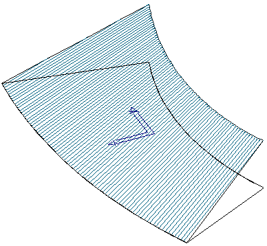
Once these have been defined, the Panels can be quantified using the Estimate > Tapered-Panels > Tally command. An example of this is as below:
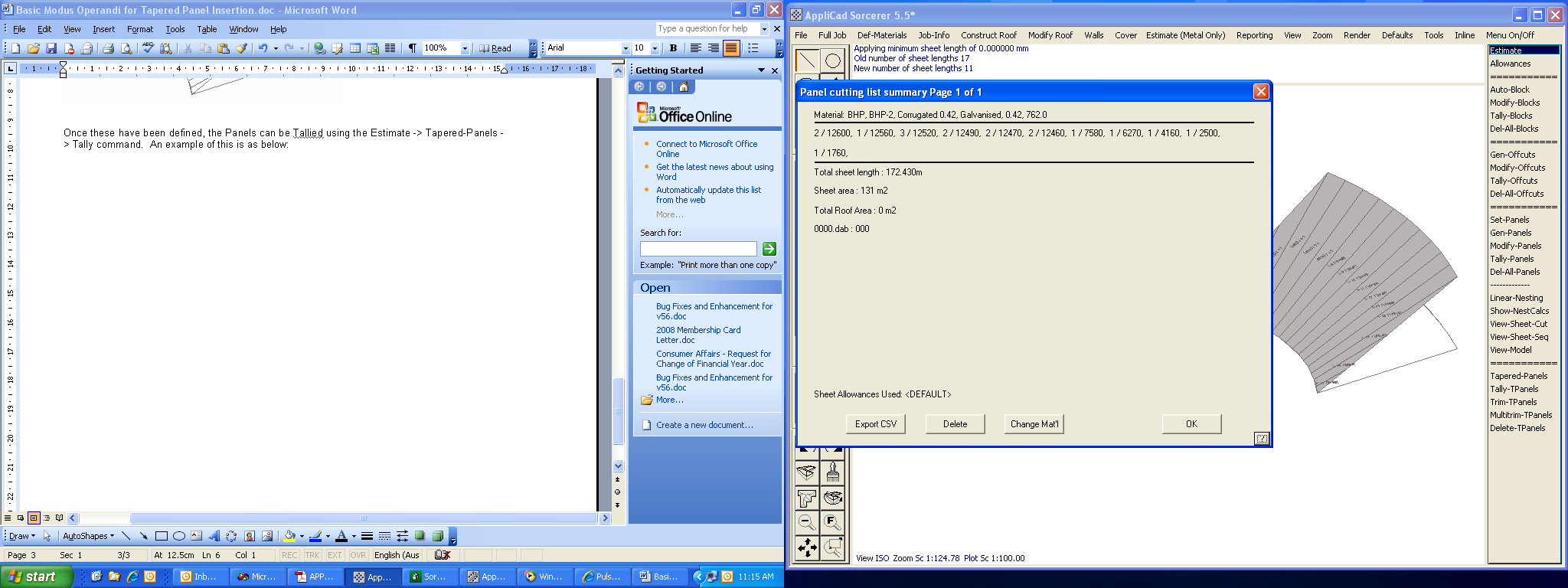
Trim Panels
If a Tapered Panel needs to be trimmed around a roof feature, the Estimate > Tapered-Panels > Trim command can be utilised. As an example, we have provided some graphics that may be required to have the panels trimmed to.
In this example, we would normally trim the 2 centre panels, thus leaving the 2 outside panels at their maximum lengths for trimming in the field. Part of the panels actually extends to these lengths:
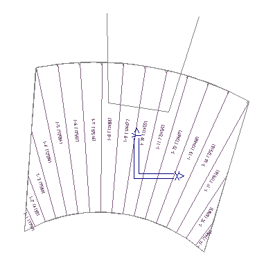
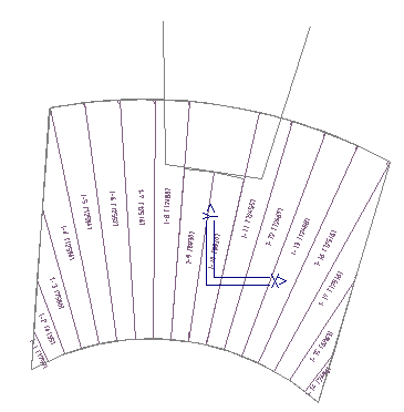
When selecting the command, we simply select the panel to trim and then select the location to trim the panel to. In this instance, we can simply snap using the centre mouse button or just use the left mouse button. Re-Tallying provides the new cut lengths prior to Reporting the job.
The Multi-Trim function allows you to trim many panel lines at a time.
Place Dimensions
The Place-TP-Dimensions feature allows the user to place documentation on the roof drawing about each panel, so that construction information can be included along with the roof plan/drawing. This is useful when panels are being constructed on-site.
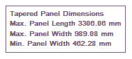
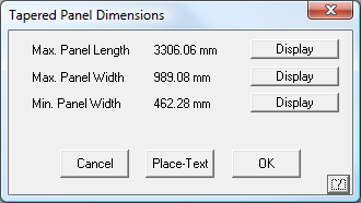
The user must first select the defining circle/arc that determines the Tapered Panel path. When defining Tapered Panels, this is the first circle/arc selected. Once selected, a dialog box will appear highlighting the 3 major items that can be displayed, such as the Maximum Panel Length, and the Panel Maximum and Minimum Widths. Selecting the Display button allows the user to define what to display and then selection of the Place-Text button allows the text to be placed onto the Drawing in an appropriate location.
Some very elaborate shapes may be created and panels calculated for. The example below is just one more situation. Almost any combination of shapes where the defining edge is an arc.
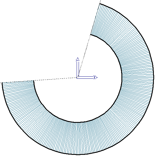
Delete Tapered Panels
This function deletes a set of Tapered Panels by selecting the defining arc/circle.
Cranked/Crimped Panels
The software will automatically recognise any of the following base shapes and complete the fabrication table for you, with dimensions. Any other profile may also be created and dimensioned, but as the shape is not pre-determined, the dimensions may end up in an awkward location on the drawing.
“Standard Shapes”

Construct-Roof > Section

Once the roof profile is defined, we use the [Construct-Roof > Section] command to “extrude” the section drawing along the ‘ridge’ line (although strictly speaking, there may not be a ridge).
The material is selected that is to cover the roof. The material must be curved quality material, so you may have to select regular flat roof metal material as well as curved quality metal if you haven’t selected a default material at the start.
The Process
We will create a simple bullnose roof shape as shown here.


Once complete, the software will then cost the job and generate the workshop fabrication details, automatically.
Example of the production details table, and below, the sketch that is automatically generated on the production report.

Before you can estimate a curved metal roof, first you must create the roof profile – the dark line in the sketch above. This may be done using any of the standard CAD drawing commands. It may also be done using the drawing commands in CAD.


For this exercise, since we are already familiar with the process of drawing a roof outline using Track-Outline, we may use the [Construct Roof > More > Track Line] command, or we could also use the CAD functions.
Insert line up, length 900mm, the add another line at direction 80 (degrees), length 2750.


 Next select [CAD > Arc > Fillet] command, and enter a radius of 350, then select the ends of each of the lines where the fillet is to be constructed.

This command adds a filleting arc between the two lines, using a radius you define, and automatically trims the lines back to be a tangent to the arc.
And you end up with this:

Create the Roof
To actually create the roof using this section profile, we use the [Construct-Roof > Section] option from the main menu. You are prompted to indicate the entities that define the section, and you will select the line and the arc and the line in our drawing. You are then prompted for the roof Section Defaults. We need to select metal, select a storey (so the correct pay scale is used) and the length of the roof – as below:

The section is then projected along the length, and this may best be seen by selecting the ISO (isometric) view. You may also find that the perspective view is helpful – Pulldown Menu View > Select > Perspective. You can choose between four predefined perspective views.

And you will get this view of your roof.

Once satisfied that the roof shape is correct, you must select your material. Because roll formed curved roofing material is usually a heavier gauge or higher tensile strength, we must have previously defined a curve quality material. As well as selecting regular material, you must now select curving metal – main menu [Cover > Select Metal].
Note – The dialogue box below shows the regular or straight material we selected, and the curving metal on the right hand side. You must have a curve quality panel/sheet profile defined for it to appear in this list – this section of Setup refers to how.

 Estimate > Tally Panels
To quantify the panels, simply select from the menu, [Estimate > Tally Panels]. Answer the question do you wish to tally panels, [YES]. And you’re nearly done.
The panel list will be displayed similar to that below:

The quotation is completed as for a regular roof, select either [Reporting > Supply Only] or [Reporting > Supply and Install].

Then print the fabrication report/order form, the purpose of this whole exercise. Select Reporting > Drawings and Arc Roof Production Dwgs.

You will be prompted for the [depth of the panel] – this is important because the actual length of the panel is the outside dimension, not the inside shape.

And the notional pitch for information only.

And that’s it! The report will be created and then you will be prompted to print it.
Example of a Fabrication Report for Safintra. The report may be edited just like a regular template, except that it is in a file called CRANKING.Dab in the User folder. There are two templates, one for the ‘standard’ curved shapes and the other for custom shapes that the software determines doesn’t fit the constraints of a ‘standard’ shape.

There is no real constraint to the shape either. If you can make it, then draw it!


The software will still determine the number of sheets and how they’re to be formed.