Contents
- 1 Walls
- 1.1 Track Wall (Outline) Perimeter
- 1.2 Track Single Wall
- 1.3 Draw Single Wall
- 1.4 Create Wall
- 1.5 Track Edge
- 1.6 Project Wall
- 1.7 Add Gable
- 1.8 Merge Gable
- 1.9 Orientation
- 1.10 Openings
- 1.11 Show / Hide Walls
- 1.12 Show/Hide Direction
- 1.13 Change Direction
- 1.14 Tally Walls
- 1.15 Wall Material Menu
- 1.16 Wall Allowances
- 1.17 Select Wall Material
- 1.18 Generate Wall Panels
- 1.19 Modify Wall Panels
- 1.20 Set-Identifier for Wall Plane
- 1.21 Tally-Cutlist of Wall Panels
- 1.22 Delete Wall Panels
- 1.23 Wall Flashing
Walls
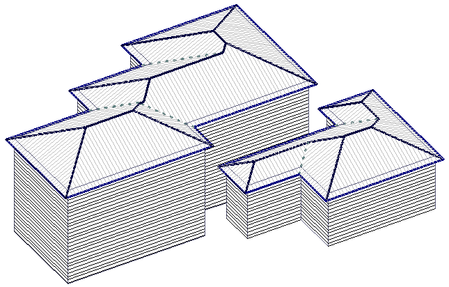
 The Roof Wizard will allow you to model roof AND walls, or just walls by themselves and check that the model is correct; then extract a detailed quotation for roof cladding and/or wall cladding, and trim – labour and materials. You have the option of tracking or digitising (tracing) the wall perimeter from plan view or tracking or digitising the walls in elevation. The best option will be determined by the information you receive.


 Track Wall (Outline) Perimeter
This is the basic command for drawing wall perimeter lines when viewed in plan or top view. To create the walls, you must project them after you draw the wall perimeter lines. You would use this command to draw the wall lines given the direction and length of each wall perimeter line.
When you select [Track-Walls], you first select a starting point, then the Track Lines dialog box is displayed.
This dialog box lets you enter directions by clicking one of the accelerator buttons (up, down, left, right), or one of the half angle directions (\ or /), or by entering the direction directly into the direction field. The direction is defined as 0 up the screen then positive clockwise. This is much like a compass bearing approach. The distance you simply enter directly into the distance field.
When you want to insert a new wall line, click Insert or hit the enter key. Then you will see dotted wall lines drawn on the screen, annotated with a wall number and the length of the wall. You will also notice that the shape is automatically zoomed to fit the screen.
When you want to automatically close the shape, click [Close].
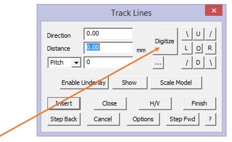
If you have horizontal and vertical distances defining the wall (rather than direction and distance) then click Hor-Vert. If you make a mistake with an input, click Stepback. If you want to re-enter values you stepped back over, then click Stepforward.
When you have finished entering walls, click Finish. When you click Finish, the wall lines are drawn.
You can enter the direction more quickly by using coded input. That is, if you type u50 in the distance field, then click enter, this input is read as Up 50 (whatever the units are, feet or millimetres). You can also use the characters of d, l and r for up, down, left and right.
Digitise Wall Perimeter
You would use the digitise option command to digitise wall perimeters from an underlay image, or if you know the coordinates of the wall corners. When you select [Digitise], you enter the constrain angle and the constrain length. These values are used to round your input to some “nice” values. If accuracy is important, then set both of these to zero (0) so that no rounding will occur as you select points on screen.
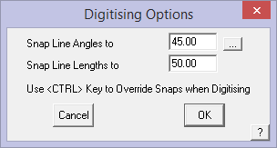
By clicking [OK] you will then be prompted to enter the required storey. Simply enter the storey and click [OK] to continue. When you digitise each corner, you will see a dotted wall line drawn as well as the length of the line.
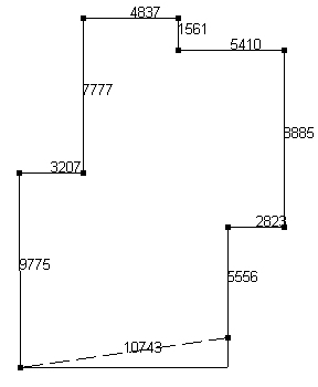
After digitising a wall outline
You will notice that when you close the outline by snapping to the last point, the last leg is adjusted so as to maintain the constrain angle you set earlier. If you do not snap to the first point to close the outline but click the right mouse button, the Close dialog is displayed.
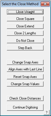
Close Straight This simply joins the last point to the first point
Close Square This creates another corner
Close Extend This extends the last direction to intersect the first wall.
Close 2 Lengths Prompts the user to close to a pre-defined line length
Don’t Close If there is a gap between the last and first points, then it does the same as the Close Straight method
Step Back Allows the operator to back track in the event that the line digitised is incorrect.
Change Snap Axes Allows the operator to change the direction of the Construction Plane (CPL) so as to continue digitising at a different orientation angle to the previously digitised lines. To access, when you need to change the CPL direction, right click the mouse and then select the option. The operator is prompted to select the origin of the new CPL, then the X axis of the CPL and then the Y axis of the CPL. Then select [Continue] Digitising. This may be repeated as many times as required until the job is completed. To finish, right click and select Close Straight or Close Square as required. The CPL may be reset to normal model origin by selecting
Reset Constraint Axes. It is also useful to have the constrain angles set, typically to 45° so as to ensure that your outline is square at all corners.
Align Axes with Last Line Rotates construction plane axes with last digitised line.
Reset Snap Axes Resets the snap axes to original settings.
Check Close Distances This command allows you to check the final two distances before you close the outline.
[Continue] Digitising Lets the operator back into the digitise process.
To enter exact coordinates while digitising, you would first know what the wall lengths are. At the relevant prompt in the prompt area of the screen (typically at the bottom of the screen) you would enter (x,y) coordinates in one of the following ways immediately after the prompt –
Locate next point LOC>:
Examples are –
Locate next point LOC> 10, 0 {10 units in the x and zero in the y}
Locate next point LOC> -10, 0 {-10 units in the x and zero in the y}
Locate next point LOC> 10’6”, 0 {10 foot 6 inches in the x and zero in the y}
Locate next point LOC> 10.5, 0 {10.5 feet in the x and zero in the y}
The above coordinates represent absolute coordinates whereas you could use incremental coordinates. Incremental coordinates are with respect to the previous point you enter.
For example, to draw a building 20 foot long and 50 foot wide, you could enter the size as:
Locate first point LOC> 0, 0 {Make 0,0 the starting point}
Locate next point LOC> i 50, 0 {Move 50 feet in the x}
Locate next point LOC> i 0, 20 {Move 20 feet in the y}
Locate next point LOC> i -50, 0 {Move -50 feet in the x}
Locate next point LOC> i 0, -20 {Move -20 feet in the y returning to 0,0}
Remember that this command simply draws wall perimeter lines or outlines and that you must project the wall lines to form walls on completion.
 Draw Walls
Select Walls > Draw Single Wall command to digitise wall perimeters, one or multiple walls at a time from the top or plan view. The usual constraints will be whatever you last used, typically multiples of 45° and 10mm (1/2″). This will force the wall lines to be square and rounded to the nearest 10mm (1/2″ increment), thus substantially improving digitising accuracy.
Select the wall corner on the underlay plan and left click at each end. Use the middle mouse scroll function to get closer to the corner if required. This helps in selecting the corner more precisely. Then zoom out, and back in to capture the other end of the wall line. Note that you cannot use middle mouse snap, because there is no line end point to snap to – the underlay is a bitmap or pixel image, there are no wall lines yet.

Extra precision is possible by typing the actual length of the wall line using the direction prefix U, D, L, R (up, down, left. right) in the prompt area – for example R2750 will draw a line precisely 2750mm, instead of being +/-10mm of the digitised location.
The wall line will be inserted. Be aware that if an edge changes from one wall thickness to another along the wall in the same direction, you need to split the line at the change of material. The line needs to stop and start again so that a different material can be applied at the next step.

After selecting the end point, you may continue in a new direction for the next wall line. Right click the mouse to finish that line and start a new line. [Continue] digitising more wall lines until you have captured them all. If appropriate, consider inside versus outside of the wall and aim to select the outside at all corners if the definition is outside.

The walls are drawn on the CPL (Construction Plane) which would usually be the floor in our situation where we have not defined the roof. At this stage we are not fussed about the type or thickness of the wall material. This will be set in a subsequent step.
The command will also ‘snap’ the line end point to the Z of any intersecting lines that it finds within the pick box on the cursor (the little square at the intersection of the cross hairs) and the prompt area will confirm that a line has been ‘snapped to’. This ensures that lines are neat and tidy and the required length.

Figure shows traced wall lines over scaled PDF underlay. Model is full size after correctly scaling the image.
The wall lines are on the CPL and essentially define the location of the wall base lines. They are ready to be projected as required – to the roof plane or to a height.
 Track Single Wall
This command allows you to track around the outline of a single wall in elevation. As with Draw-Single-Wall you can insert multiple wall elevations on the one job. The basics of this command work the same as Track-Walls (described above).
Draw Single Wall
This command allows you to digitise or track around the outline of a single wall in elevation. This is typically used to create a wall using an underlay image from the Microsoft Windows clipboard of a PDF document or a scanned image of a wall elevation drawing.
For walls, clip the image of the wall elevation:

Digitise the wall (Walls > Draw Single Wall) and generate the wall panel cut list (requires AppliCad Roof Wizard module) using function Walls > Apply Wall Set-Up > Generate Wall Panels.

These functions are easy, quick and accurate (as accurate as the images permit). For more details on digitising, refer to the section on digitising roof geometry above. Note that the software requires you to digitise the wall base last (and reminds you in the prompt area), This is so that the panels are aligned as specified relative to the wall base.
If you happen to digitise in a different order, and the wall base is not done last, you get a wall corner instead of a wall base. The fix is simply to use the Tools > Change Line Type function (or double click the line) to change each line to the correct attribute and then the panels will be aligned as required. If the wall base is not 100% horizontal, then the software uses the wall top line to align the panels as shown below.

Note: When using this function, the software tags the wall corner ‘External Corner’ by default, as this is the more likely requirement. If the corner is an ‘Internal Corner’ use the function Walls > Define Int Corner to change the line to internal corner, or Walls > Define Ext Corner to switch it back again.
The software uses the wall top to align the cladding panels, so if you need the panels to be aligned vertically on a wall that is ‘crooked’ top and bottom, you need a short piece of wall top that is horizontal – like this example:

where we added a 50mm/3″ length of wall top line. Remember to still digitise the wall base last and all lines will be correctly identified according the construction rules.

In the event that the wall outline doesn’t lend itself to orienting the panels correctly, such as a sloping Wall-Top line like the examples shown here, the easy fix is to digitise the exact outline required, then use the Modify Wall Cladding/Siding option and realign the panels to the required wall line. (Described in more detail later in this section.)
If you want to be able to align panels for walls in a different direction, aligning to the line serves 2 purposes, it allows the panel to be aligned through a point (the line end point), but the line also allows for the direction of the panels to be changed.

Select the wall plane to change and then the line to align the cladding panels with and you’re all set –
For vertical panels:

For horizontal panels:

If you wish to align the panels through a location where a line doesn’t currently exist, simply use the Smartlines > Copy Line function and copy it to the required location. For example, aligning panels through the apex of the gable end.

‘Snap’ the line to the apex of the gable end.

The use the Modify-Panels function, Realign Panels, select the new line and you’re done. Don’t forget to delete the line if you copied a line with attributes or you will be adding to the quantities for that line. You could also use the CAD > Insert > Line > Vertical Length function, but copying an existing line is quicker.

 Create Wall
This command allows you to select any closed polygonal shape and create a wall plane upon it.


Very useful for restoring wall planes after modifying wall edge lines etc as shown here. We use the [Smartlines] functions to delete walls, and trim and cut lines, then [Create Wall] to reinstate the wall planes. Follow the prompts…
 Track Edge
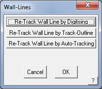
The Walls > Track-Edge command lets you realign the wall profile to whatever shape you wish. Select the option and you are prompted for the method of re-tracking the wall edge.
Re-Track Wall Line by Digitising This option automatically moves the construction plane from horizontal to the same plane as the wall you selected to modify – indicated by the CPL (Construction Plane) icon. A construction line attaches itself to the start point of the selected wall line and waits for you to digitize the next apex or corner of the wall.
Once you have the wall shape required, right click to cancel and the outline closes to the end of the line and the wall reconstructed.
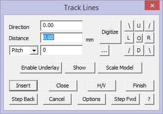
Re-Track Wall Line by Track-Outline This option moves the construction plane onto the plane of the selected wall. A construction line attaches itself to the start point of the wall line and then presents the Track wall edge dialog for the operator to redefine the wall edge.
After selecting the wall edge to track, the Track-Edge dialog is displayed.
Here you enter the new wall segments, starting from the wall line start point, and ending at the wall end point.
You can select the top or bottom of the walls as well as the tops or sides of an opening. If the edge is not square or regular in shape, you can use the [H/V] option to define the edge with both horizontal and vertical offsets from the start point or previously defined point.
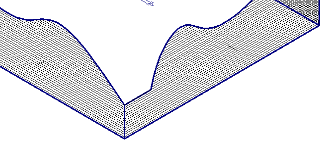
Re-Track Wall Line by Auto-Tracking This option will automatically track the profile of a roof line, or a site line for example, to adjust the shape of the wall to match the shape of the roof or the terrain.
Select the option, then select the wall line to modify. When prompted, select the line(s) to adjust the wall line to. The wall is projected vertically either up or down as appropriate to exactly conform to the shape of the defining line.
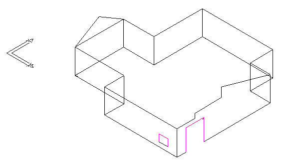
After tracking the top of a wall.
Below – [auto-track wall] to an adjacent curve – such as a curved ceiling.
 Project Wall
This command automatically projects the wall lines in the model down by an amount you enter, to the construction plane or selecting one wall at a time and project that to a specified height. After you select the command, you are prompted to enter the wall height. The default value is the eave height you have entered earlier. The original wall lines are modified to become the top of the wall then are projected down the height you want. Note that the original wall lines are deleted.
The following diagram shows an elevation view of a roof confirming where the walls are projected from.

After you draw the wall lines, it is necessary to project them to their actual height. Walls may be projected up or down from the digitised wall lines. In order that the wall lines are compatible with the AppliCad roofing products, the wall lines you draw to create the perimeter for the roof geometry are at the top of the wall, if you have a roof in your model. If you do not have a roof in your model then the wall lines would typically be on the floor level (the CPL).
Select [Project Walls], a dialog box is displayed.
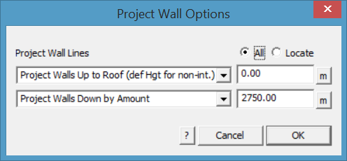
[Project Wall Lines] has multiple options that relate to whether the walls project up to the roof plane(s) and/or down to floor or ground level.
Project Walls Up
The [Project wall Up to Roof] simply takes all walls up to the under side of the roof planes. If a wall line extends beyond the perimeter of the roof for any reason, you can set the wall height to extend to. You might use the Measure function [m] to establish the height of the eave line to set the correct height.
If the walls are to be projected to the whole roof, then select the [All] button. On occasion, it may be necessary to select the walls and roof planes separately then use the [Locate] button. The walls will stretch up to the slope of the underside of the roof plane. Note the option for when the walls do not intersect with a roof plane, you must define a project distance or height (def Hgt for non-int = define height for none intersecting walls).
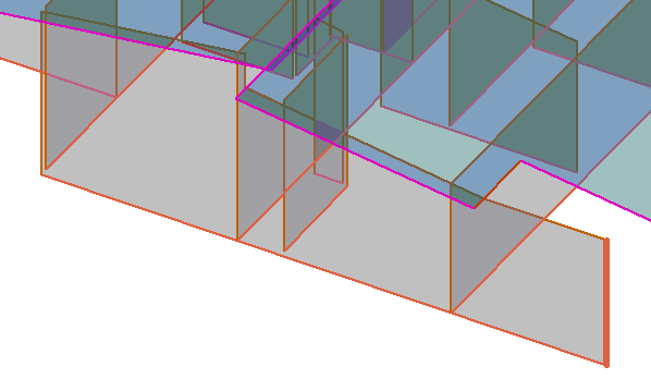
A wall line that extends beyond the roof with the height defined to the height of the eave line.
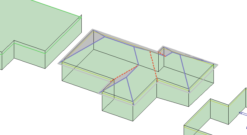
With a pitched roof, the distance from the ceiling height to the underside of the rafter is automatically calculated and the wall top is projected to the roof. It is NOT the same height as the eave height. You may choose to adjust this if required.

You would typically use the height calculated. In the box displayed above, this is the actual wall height for an eave height of 3000 and a roof pitch of 30°. After you enter the height of the walls, the wall lines are projected down to construct the walls. Each wall comprises the boundary lines and a plane entity.
![]()
Hint : It is a good idea to change your view to isometric at this stage so you can more easily see the 3D walls and select them to perform operations on later – use the function View > Isometric. You can rotate the iso view to better see what the walls are showing.
Define Int/Ext Corner
When using the function Track or Draw Single wall, the software tags the wall corner ‘External Corner’ by default, as this is the more likely requirement. If the corner is an ‘Internal Corner’ use the function Walls > Define Int Corner to change the line to internal corner, or Walls > Define Ext Corner to switch it back again.

Project Walls Down
The second options relate to projecting down (if required). [Project Walls Down by Amount] allows you to set the exact amount down or [Project Walls Down to RL (Z Hgt)] projects down to the CPL.

Note the option for when the walls do not intersect with a roof plane, you must define a project down distance (def Hgt for non-int = define height for none intersecting walls).
The wall lines are automatically tagged as Wall-Top, Wall-Base and Wall-Corner. These identifiers then define the type of flashing imposed on each line type. The following shows walls projected without the roof.
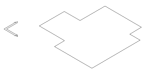
Walls before Project
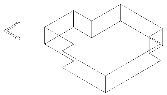
Walls after Projecting down to the specified height
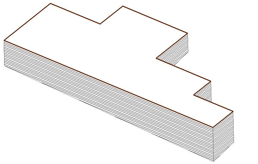
 Add Gable
This command inserts a gable plane on top of a wall. After you enter the slope of the gable, you then select the line at the top of the wall. You must have already projected the wall lines.
A gable plane is then inserted on top of the wall. You can keep it separate from the wall below it, or you can merge them together later on. You will be prompted whether you wish to merge the gable plane with the wall plane.

After adding a gable to a wall top line
 Merge Gable
After you inserted a gable on a wall, you may wish it to adopt the same material and orientation as the base wall. If you do, then you must merge the gable plane and the wall plane.
Merged gable Gable not merged

To merge them together, first select the gable plane, then the wall plane.
![]()
Hint : It is a good idea to display the hatch pattern on the planes at this stage by selecting Show-Walls. Remember that the hatch pattern also shows the orientation of the siding.
 Orientation
When the walls are first projected, they default to adopting horizontal siding. This command lets you change the orientation from horizontal to vertical (and vice-versa).

![]()
Note: Walls showing horizontal and vertical siding as a hatch pattern. Panel direction or orientation lines are only visible if Hatching is the default setting for your wall planes. If you have Filled planes as the default setting, you cannot see the direction of the panels until after panels have been applied. Panel orientation can be changed after panels have been applied and they will automatically re-draw.
 Openings
This command lets you insert door and window openings into a selected wall. You may also create a library of pre-defined windows and doors.
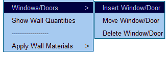
Select Walls > Window/Doors .
The following dialog is displayed. Type in the required description, indicate whether it is a door or window and the required opening size and then click Add. This creates a new opening item that may be used on your job.
Typically you would define the sizes of your favourite supplier. Once they are defined, you don’t have to do it again.
The delete button [x] removes an opening definition from the list. The [v] down button allows you to see all previously saved windows and doors in your system.
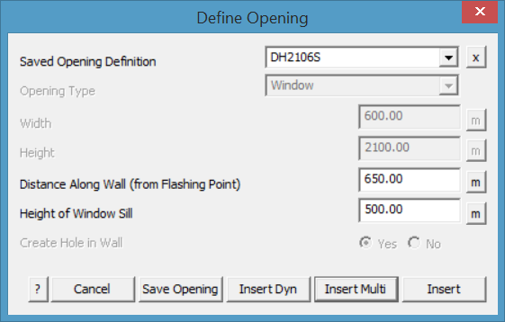
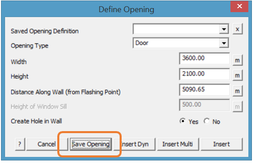
After you select the wall line at the base of the wall that requires the opening, the Define Opening dialog box is displayed. You can select from a list or define a new opening.
If this is a non-standard or custom door, then simply set the height and width of the door as shown and then the distance along the line measured from the flashing point at the corner. If you think that you will use this opening again, select Save Opening – this adds the new door to the list for later re-use.
Other functions on this dialog box:
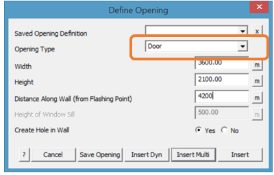
Opening type This toggles between Window and Door. A door will always be inserted from the base of the wall.
Distance along the wall The distance from the end of the wall line to the near side of the door. Notice that each of the distance fields have a [m] measure button next to it so that you can measure the distance or length of an opening on an underlay image while digitising.
For a door, you see the following parameters:
Width of door The width of the door.
Height of door The height of the door.
For a window, you see the following parameters:
Height of window sill The height of the window sill
Width of window The width of the window
Height of window The height of the window
After you enter the parameters, click Insert to insert the opening. If you make a mistake inserting the door or window, you can cancel the function (right mouse ) and select Undo to delete the previous opening.
Move a Window/Door
The Move Window/Door option (pulldown menu) allows the operator to move an opening in the wall plane. The selected wall is displayed on its own in the construction plane and the opening may be dynamically moved. The coordinates from the lower corner of the wall are displayed in the top left of the working area of the screen. You may also move an opening from one wall to another.
You may also select Delete Window/Door from the Pulldown menu.
Odd Shaped Openings
Openings may also be inserted by ‘Tracking’ or ‘Digitising’ the outline of the opening in the wall such as an architectural window feature, or Auto-Tracking an existing line, circle or curve on the wall.
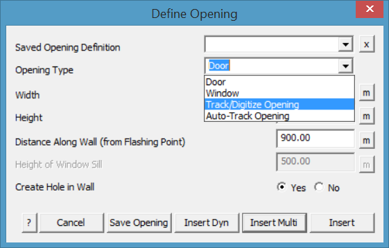
For example:
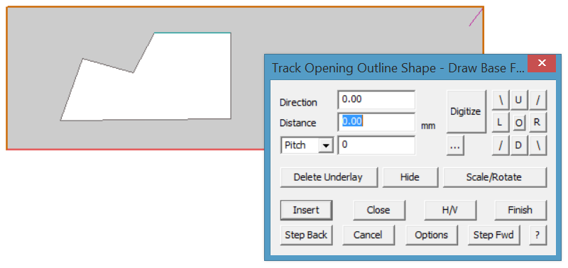
Insert Openings in Dynamic Mode
Windows and doors may also be inserted in Dynamic mode – [Insert-Dyn]. In this mode, the described window/door is attached to the cursor while the workspace is flipped into the plane of the selected wall.
The window/door may be placed by sighting it against other features.
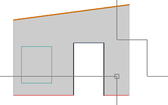
While in ‘Dynamic’ mode – you may also use the inline functions to place the window/door using precise measurements. When prompted to place the window/door, the crosshair cursor is displayed, move it up to the pulldown menu and select [CAD > Inline] and the most appropriate function for what you are doing from the options that include ‘reference point’, ‘mid-point’ or ‘distance along’. Follow the prompts and place the window/door at the required location.
When you are finished inserting openings, click the right mouse button to [Cancel].
Alignment of Openings
If the bottom of the wall (line selected) is not level, then the window sill simply follows the direction of the reference line.
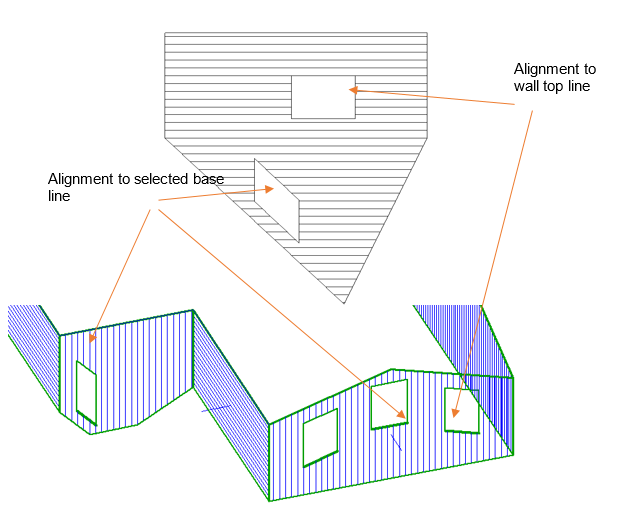
The window or door will also align with a top edge as well. For odd shaped walls, the wall may be re-drawn using the [Track-Wall-Edge] function described above. The line is automatically tagged Wall-Top or Wall-Bottom as appropriate. Openings will automatically align to these wall line types.
If the gable end has been inserted using the [Add Gable End] command, you will have to change the line type to Wall-Top to add the window or door aligned with that line. Use the Tools > Change-Line-Type function to achieve this. Often it is easier to select the wall lines to align with in the ISO view. The software will then switch to the appropriate view for positioning the opening.
The lines describing the openings are automatically tagged as Door-Edge, Door-Head, Window-Edge, Window-Sill or Window-Head as appropriate to the geometry.
Multiple Openings
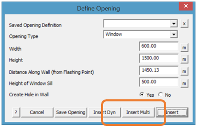
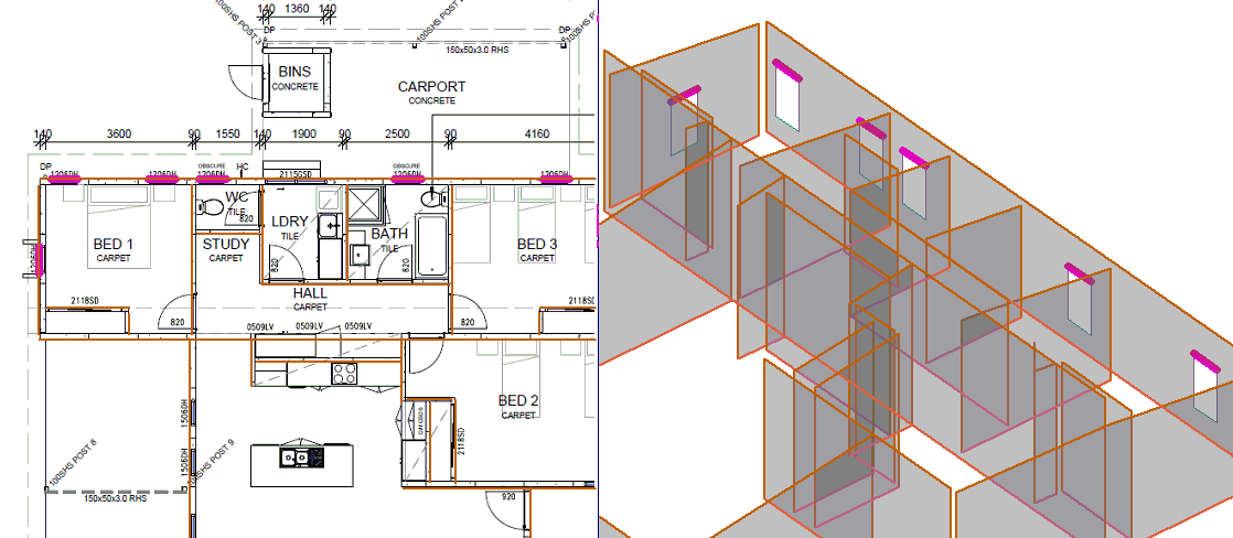
If you have to insert a few windows or doors along the same line, such as we do along the back wall in our example, use the option [Insert Multi] on the dialog box. Select the openings command, select the wall line to attach to and then set up the correct size a sill height for the window, (or select from a pre-defined window). Then start placing your openings along the wall one after the other.
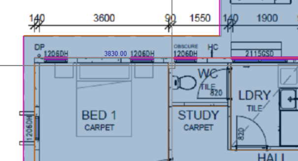
In top or plan view, the user gets a distance measurement displayed along the wall.
Distance to edge of each opening… (viewed from the top or in plan view)
Distance to edge of next opening…
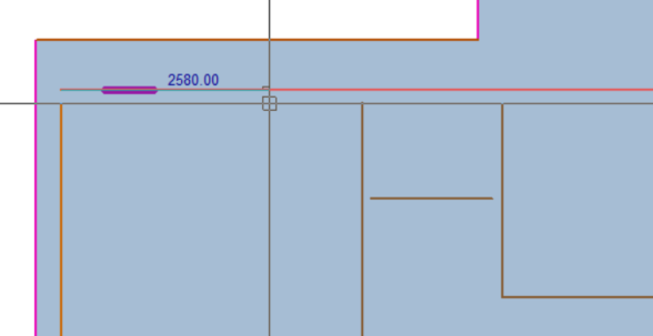
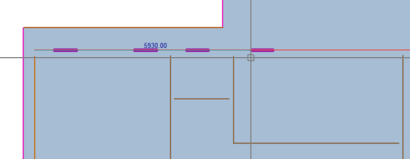
And so on.
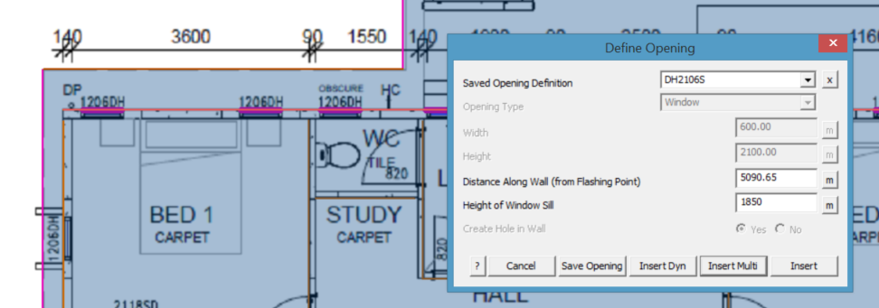
When the wall has all its openings, cancel that wall (right mouse click), select a new wall and go again until all openings have been installed on each wall.
The same process is applied to inserting a door in a wall. Select opening type to be door or select from pre-defined doors saved previously. It is often useful to work in split screen mode for doors as well.
No Hole
In some situations, wall panels are cut on site to suit the structure, essentially the hole for the opening is waste material. For this situation, select the option Create Hole [No]. The window or door is shown, but the wall cladding is not removed.
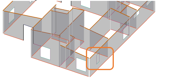
Window shown in position without the hole being cut out.
Defining Windows and Doors
If you have a regular supplier of windows and doors, it is very effective to have these predefined as has been discussed above. When you define a new window or door, select the [Save Opening] button and you will get a dialog displayed to give the opening a name. Use a name that will be easily recognised by all users and select [OK]. The definition is saved and ready to be used again and again.

Openings – A Unique Case
Inserting multiple doors into a wall that are taller than the wall, effectively “breaks” the wall and will cause issues. The code assumes that any hole in a wall is a secondary occurrence and so assumes the first plane area in any wall is the whole wall and the part that you want to insert the opening into. In this example below, we insert openings of full height into the lower wall. We start at the left:

If we insert the first opening, we get the following:

The problem now is that the wall is broken cleanly in two, but it’s still a single plane. When the “Remove Holes” command is called, which normally removes windows only (but in this case the door that carves the wall in two) it also removes the second part of the wall, assuming that is also a ‘window’. Any subsequent attempt to insert the window/door fails because the wall is now defined by the code as that little bit on the left hand side. But, if you insert the opening in the other end of the wall first, then the second opening where this one is, it we get the following result:

If you then alternate each side from this first one, it generates the wall as required, although now it is effectively a series of small wall segments:

 Show / Hide Walls
Once you have modelled some walls, you can display a hatch pattern on the walls. This makes it easier to select the walls to perform some operation plus it confirms the Roof Wizard software recognises those planes as walls (and not just plane entities). The hatching will either be vertical or horizontal which depicts the style of the siding being vertical or horizontal. You can change the style using the [Hor/Vert] command.
If you have turned the hatching on using [Show/Hide-Walls], will simply turn off the hatch pattern. You can still select the walls by clicking onto their individual tick marks located in one of the corners of the wall outline.

Walls before [Show-Walls]
![]()
Note: The appearance of the walls on screen is determined by the System Preference settings for Planes. You can have hatched planes or filled planes.

Hatched planes

Filled planes
 Show/Hide Direction
This command shows or hides you the direction of the wall. By clicking this command, lines are drawn at the centroid of each wall. You should interpret the side the line points to as the outside of the wall.
Change Direction
This command allows you to change the direction of the wall. This is done by simply clicking on the wall plane that you would like to change. It is important that this direction is correct for formatting the wall drawings during the creation of the wall reports.
 Tally Walls
At any stage when you are modelling the walls, you can report on the geometric quantities for the walls. When you select Tally, the specific summary of quantities are displayed on the tally dialog like that below.
Here you see the total wall area, total line lengths for the openings as well as the number of each line type. You can also export these quantities to a CSV (comma separated value file) for import into other computer systems for further analysis.

The Print option allows the operator to print the contents of the Wall Quantities Tally screen to a Word or Excel template file.
Wall Material Menu
 Wall Allowances
This command allows you to set allowances for your wall cladding. These allowances will be applied to your wall panels/sheets. Panel allowances for Wall/Siding panels and work in much the same way as they do for roof panels. The allowances can be modified through the Walls > Allowances menu option and present as per the image displayed here
Panel Allowances for Intersection with – Applies the specified additional length to the calculation of a panel length at the intersection of the specified line type. If no additional material is required, set all to zero.
Combine similar length panels – After you generate your panel list, lengths which are less than this amount apart, are assumed to be the same length and are merged together. The shorter lengths are merged into the longer lengths.
Round off panels to next – This allows you to enter in a number to round your panels/sheets up to, for example the next 10mm
Annotate panels with – Here you can set how you want to annotate the identifier for each panel when you generate the cutting list using Estimate > Tally-panels. You can have the identifier, the length, both the length and identifier, or no annotation at all. If the operator requires the wall panel lengths to be rounded up to a whole number, then the option exists to display the rounded number as well.

Annotation Text Size This is the size of the annotation (in millimeters) on the wall panel placement drawings.
Apply the panel minimum length If you have set a minimum panel length below this number will be grouped together to create panels longer than this number.
Default Direction for Panel Insertion
Sets the starting direction for panels inserted on the wall planes.
Saving the allowances away to a named configuration allows different panel allowances to be selected depending on the user requirements.
![]() Note: Unlike roof plane offsets, where you have to specify whether you want these offsets applied to each panel directly or you wish to create an “as-built” or offset plane, the offsets for walls are immediately applied without this requirement. That is to say, that once defined, they will be applied when you next generate wall panels.
Note: Unlike roof plane offsets, where you have to specify whether you want these offsets applied to each panel directly or you wish to create an “as-built” or offset plane, the offsets for walls are immediately applied without this requirement. That is to say, that once defined, they will be applied when you next generate wall panels.
 Select Wall Material
This command selects the material you want to use for the cladding. Firstly, you select the material you want from a list. Notice that we store cladding materials and roofing materials in the same database, as frequently they are the same product.

You should have already defined the cladding material using the Set-Up > Metal-Panels command and the information saved in the file sheeting.csv. This is the same file where roof panels/sheets are also saved. The insulation is defined with Set-Up > Insulation and will be displayed in the list on the drop do box.
Once defined use Walls > Apply Wall Set-Up >Select Wall Cladding to select the wall pay rate, allowances, material and fasteners you wish to apply to the wall.
You will also select the required wall insulation through this dialog box. It is good practice to check the accessories that have been previously defined for the selected panel. These may change from a roof application to a wall application.
The calculation of wall panel lengths when divided into [Stock Lengths] ensures all lengths created and specified as stock lengths are used. The calculation reduces the amount of waste and returns lengths of material in-line with the cladding stock lengths.

The internal and external flashing allowances further provides benefit to the calculation of the correct panel lengths, with these allowances either pushing the calculations up to the next panel length or being absorbed into the current stock length.
On One Wall
The cover command allows you to assign a different metal cladding material to one or more wall planes.
When you click this command, the cladding material dialog box is displayed. If you have already selected a cladding material, then you see the following dialog box:
Here you set the new material specification you want by clicking Change and selecting the required panel from your list.
After you click [OK], you then select the wall planes you want to adopt this material.
On One Panel
This command lets you change the materials used on one or more panels. For your convenience, the panels are highlighted to make them easier to select.


You can see the result by regenerating the cutting list using [Generate Wall Panels]. When the cut list appears, change to the different material by clicking on the arrow to the right of the material list shown. You can list the individual panels or the complete list of panels. Also displayed is the total length of coil required for this job, plus the area of panels compared with the area of walls.
Generate Wall Panels
This command will generate individual panels on the walls using the material you have selected. If you have not already selected a panel to use, you are prompted to select one. The selected panel is then generated on each wall plane in the model, taking account of the operator defined lay direction and all openings.

After Generate showing the placement horizontal and vertical cladding panels.
 Modify Wall Panels
This command allows you to modify how the panels have been generated on the walls. By clicking on this command the following dialog will appear.

From this dialog you can set your join underlap, split siding panels, insert panels, merge panels and delete panels.
Splitting Options:
Join Underlap This is where you enter the amount you require to overlap your panels by, at a join.
Splitting Method
Use the Maximum Panel By selecting this option, any panel lengths that exceed the Length Only Maximum Panel Length will be split at this length.
Select Panel Split Line This option allows you to manually select a line where you want to split your panels at. eg a window edge, a door edge or even a wall purlin. This is especially useful if you are using panels that are cut to length and/or are supplied in a range of factory cut stock lengths as shown in the image below.

Split into Stock Lengths – If a panel is supplied as a series of stock lengths, these may be defined (refer Setup > Metal Panels) and when the wall has these panels applied, the software automatically selects the appropriate size for the length required. When the funciton is used, you are asked if you wish to display the actual length of the last panel in the run or the rounded up length that matches a stock length from your list of stock lengths as defined in Setup.

Inserting Wall Panels
Insert Cladding Panels This option allows you to generate panels on a single wall plane at a time.
Merging Wall Panels
Merge 2 Panels This option allows you to merge two panels together to create one panel.
Deleting Wall Panels
Delete Individual Panels This option allows you to manually select panels to delete one at a time.
Delete All Panels on Wall This option allows you to delete all panels on a selected wall plane.
Modifying Wall Panels
Change Panel Length This option provides the operator to individually modify the calculated sheet/panel length to suit the job. This is usually done subsequent to a site measure where small changes to the required panel length becomes necessary due to construction variations. The option requests an amount to add or subtract from a panel length.
Realign Wall Panels Allows you to align panels with a random line or the edge of a door or window aperture.
The default starting point for each wall is with panels applied and aligned with the wall corner.

But you can align the wall panels with any line in th egeometry of the model.
You might like to create a line using [CAD > Line Insert > Vertical Length] and snap the start point to the apex. It doesn’t matter how long the line is. Then align the panels with that line, aligning the panels with the highest point of the wall.

Instead of adding a line, you can copy an existing line which is even easier to do, if you wish to align the panels through a location where a line doesn’t currently exist.
Simply use the Smartlines > Copy Line function and copy it to the required location (snapping to the point at that location).
For example, aligning panels through the ridge apex of the gable end.
Don’t forget to delete the line if you copied a line with attributes or you will be adding to the quantities for that line type.

An example might be – aligned with a door edge:

or more creative still, aligned with a random line and divided into stock length panels.
If you do not get the result you need, simply [Undo] it and try something else.
 Set-Identifier for Wall Plane
This command lets you give each wall a unique identifier which is used to identify individual cladding panels as well as identifying the walls on plans and elevation drawings.
Simply select the wall to identify and enter the identifier you want.
 Tally-Cutlist of Wall Panels
This command will quantify the cladding panels into a cutting list. After you generate the cladding panels, select [Tally]. The cutting list is displayed on a dialog box similar to that below. It shows the material selected, including all material types if multiple have been selected.
It also shows a summary of the panel lengths and the number of each length to be cut; the total length of coil required to complete the job; the area of wall panels plus the area of the walls. Also shown is the database and model name for the file created for this job.
At the bottom of the screen is displayed the sheet allowance file being used. This is selected when the operator sets up the cutting allowances for a job. The Export CSV button exports the data displayed to a text file in a Comma Separated Values file that may be imported to Excel or any other program that can read text files.
The Delete allows the operator to automatically delete wall sheets/panels less than a specified amount. This would usually be done if it is expected that the small pieces can be accounted for from off-cut material.

The operator may also manually indicate certain sheets/panels for deletion. The Change Material button allows for the material used on the entire job to be re-selected and the alternate material is applied to the job.

 Delete Wall Panels
This command deletes the cladding panels from all of the walls.
Wall Flashing
This command generates the flashings for the opening trims and corners of the walls.
When you select Flashing, the Wall Flashing dialog box is displayed.
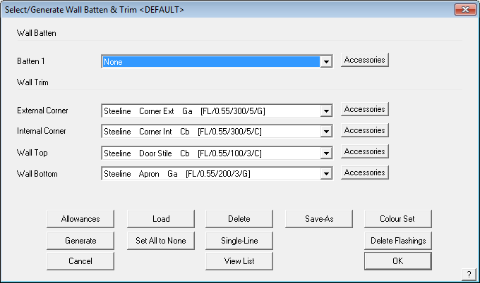
This dialog box shows you the flashing/trim material to be used on each of the line types created in the model of your walls. To change the type of trim, click on the relevant button. Selecting the [Batten button brings up the list of batten materials available for that line style. In this example we have quite a few batten material options.
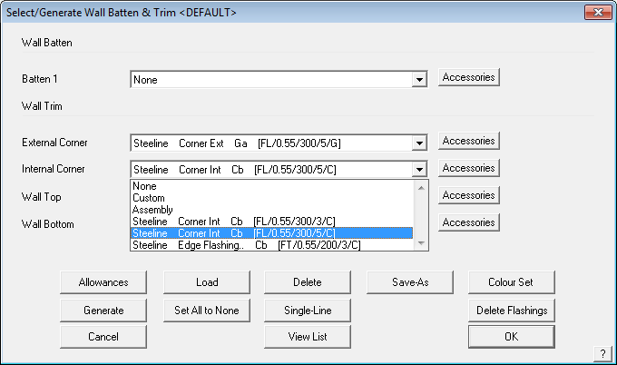
Here, you either select [None], so that you don’t want any material on that line type; or Custom, a fabricated flashing profile, usually made in a press break to a custom specification; or a bought in regular flashing item usually fabricated in a roll-former. You may also select from a Flashing Assembly which is an assembly of flashing profiles such as used on parapet caps and box gutters. All these materials must first be defined using Set-Up > Flashing. Refer to this section of the Reference Manual for more details about defining and using your flashing materials.
Wall Battens
The wall batten button Batten has an Insert/Modify option. Selecting this button opens up the dialog box shown below and allows for comprehensive set up of your wall battens/purlins.

The operator can define the batten spacing and the program provides for the spacing to use near the top and bottom and left and right of the wall plane to suit the requirements of certain building codes, especially in cyclonic or hurricane prone areas.
The intermediate batten spacing may also be set. The options for the intermediate spacing, that is the batten spacing after the pre-set batten spacing, may be a fixed spacing of the specified amount or spaced evenly along the length of the wall up to a maximum spacing.
Notice that you can also specify additional battens around openings and wall top and bottom.

Many batten/purlin configurations require the battens/purlins to be split at a wall frame. This may be the case for a typical portal frame commercial structure. If the battens/purlins need to be split, use the Divide at Wall Frame Line option then the operator needs to indicate at which frame member the batten/purlins will be divided. Individual battens/purlins can be divided or all the battens/purlins on the wall plane using the Divide All at Wall Frame Line.
If a batten/purlin is incorrectly divided, then use the Merge Batten Line button. The Delete Batten Line completely removes the Batten/Purlin from the model.
Apply All Applies battens/purlins using the spacing definitions set.
Delete All Deletes all batten/purlins from the model.
Delete Deletes the battens as selected.
Apply Selected Applies battens to a wall using the current settings. Use this to modify batten spacing on a wall by wall basis.
Continue Takes the operator back to the Flashing dialog to continue setting up wall trim.
Change Batten Changes to a different batten material.
Save Spacings Saves the current settings. Use this to set up different spacing settings for various wall systems.
Load Spacings Read into the current job, spacing settings from a predefined set.
Wall Flashing Allowances
Clicking Allowance, will display the allowances dialog box.

These allowances work in much the same way that they do for roof flashings and rely on wall directions (inside/outside) and connections to determine whether two successive flashing lines configured in an internal or external way. As such, the allowances are not automatically applied for walls drawn individually or flat. In this case, the [Single-Allow] button needs to be used to modify flashing allowance lengths accordingly.
The Run Allowance is the length added to each line length to ensure that the installers have enough material. The Lap Allowance is the length added to allow for lap joins in the material. The run allowances and lap allowances will be added to each run to compute the cutting list. The Internal and External allowance provides for extra material specifically for creating mitred corners on the trim.
Generate Wall Flashings
To generate the cutting list of wall flashings, including the battens and all associated accessory items required to install the trim package, select Generate. After the software reviews all the materials and accessories, and generates the cutting list, you will see the list similar to that below. If a roof has been quoted as well, you will get roof trim as well as wall trim in the list.
Selecting the ExportCSV button will export the information displayed in the list to a comma separated values file (a text file) of the flashing cutting list. This may be used by other systems or imported into your favourite spreadsheet program.
Selecting the Accessories button brings up the complete list of accessory items for this set of trim including clips, brackets, screws etc.
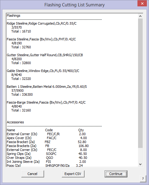
Selecting View-List will simply display the cutting list you generated earlier.
The Delete button, will delete the cutting list so it is no longer costed.
Single-Line will let you assign a separate flashing to a line you select.
Set-As-default, will set the current configuration as the default set of flashings you want to use.
Set-Colour sets the colour for painted flashings to be the same.


