Contents
- 1 Tools/Check
- 2 Show/Hide-Planes
- 3 Show LineTypes
- 4 Dimension Roof
- 5 Tools Change
- 6 Tools > Check
- 7 Check Model
- 8 Tools > Measure
- 9 Set Display
- 10 Export Image from Screen
- 11 Plot
- 12 Tally-Quantities
- 13 Verify Entity
- 14 Wizards
- 15 Define Report Notes
- 16 Define Print Options
- 17 Define Drawing Options
- 18 Edit User Templates
- 19 Modify Text
- 20 Create Flat Pattern
Tools/Check

The functions under the Tools menu have all the things you need to check that your model is correct. If the model is correct, then your quotation will be correct.
The Tools menu is your friend!


 Show/Hide-Planes
Selecting this button toggles between roof planes on and roof planes off. This command automatically cycles through the model and draws a shaded or ‘filled’ area or a cross-hatch pattern on each roof plane. It is very wise to model with planes displayed for those times when you need to select a roof plane for a command or simply to determine that roof planes are indeed present. With planes on, you can see whether planes have been correctly constructed. Remember, if there are no roof planes, there is not roof material being estimated.
The default hatch differs depending on the type of roof material on the roof plane. For tiles, shingles and shakes, the hatching runs along the plane; for metal, the hatching runs up the plane and for Low-Slope roofs, the hatching runs at an angle of 35 degrees across the plane. This helps you visually differentiate what is on each roof plane especially when you want to combine materials.
Below is an example of the ‘filled’ planes. These may be a different colour for different material categories, and darker or lighter as required.
This is set under Set-Up > Preference Settings > System Preferences > Plane Options.

The following diagram shows the different hatch patterns based on the different roof plane materials, also set under Set-Up > Preference Settings > System Preferences > Plane Options.

 Show LineTypes
This command automatically displays the line types of each line. These are tags with the prefix ENTITY TYPE:. These labels are turned off by selecting the button again.


The line type will also show the storey number in brackets so that the correct installers’ pay rate will be applied based on storey (if defined to be dependent upon storey).
The line type determines the material that goes onto that line. Showing the line type is NOT selecting the material. This is done under Cover > Flashings.
Dimension Roof
 Insert-Auto
This dimensioning command inserts dimensions automatically around the outside of the roof. Running dimensions are automatically inserted along the top, right, bottom and left hand sides of the roof model.
The following diagram shows the perimeter dimensions.
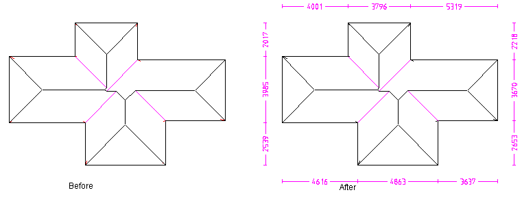
This button is a ‘toggle’ button – select it once to insert dimensions, select again to delete them. If Zones are present on the model, it ignores USER1-4 lines, as these may be in the corners and could make dimensions quite overcrowded.
The size of the dimension text is controlled by the settings in [Setup > Preferences > Dimension Defaults] and are automatically scaled to suit the size of the job. The scale is proportional to the size of the job and may need adjusting using the [View > Plot Scale] function.
 Insert Pnt-Pnt
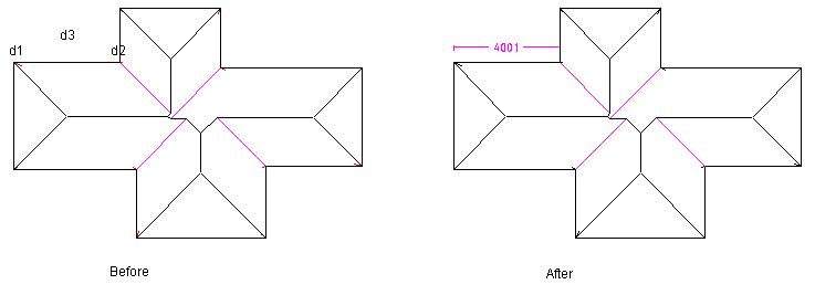
In this case, you first locate the two points you wish to dimension, usually by ‘snapping’ to an existing point using the middle mouse button at (d1) and (d2), followed by the position for the dimension (d3).
 Insert Line-Line
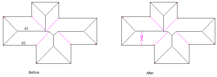
In this case, you first locate the two parallel lines you wish to dimension between. The dimension will represent the 3D distance from the first line to the second line. The position of the dimension is determined by the the point where you selected the first line. You would use this dimensioning command to detail the rafter length on a roof plane. Note that if the lines you select are not parallel, the dimension is not inserted.
If the lines you want to dimension between are boundary lines of 2d-roof planes (created by 2D Design), then you will get the 3d distance reported.
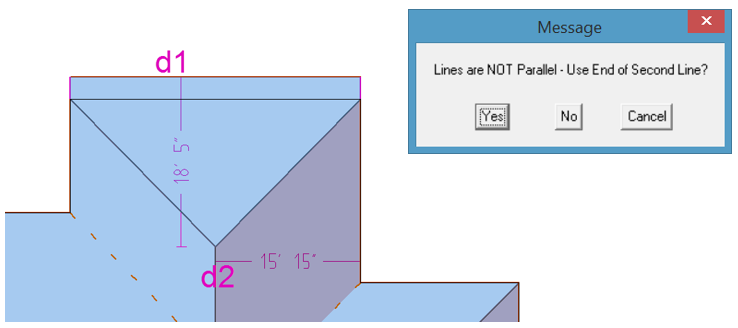
If this function is used on the eave and ridge line of a hip end, the apex will be used to determine the dimension. Select the eave line first (d1) as this sets the position for the dimension. Then select the ridge line. The reminder message is displayed, giving you the option to accept the dimension, in case you selected lines in error.
 Roof Line Lengths
This command annotates the dimension of each roof line (except for aprons). The dimension is rounded to the nearest mm (or ¼ inch) and truncated. The colour of the dimension text may be set to be the same as the line associated with it. This aids in reading the dimensions. This is set under the Dimension Defaults. They can also be set to be a distance away from the associated line to aid in the reading.

This button is a ‘toggle’ button – select it once to insert dimensions, select again to delete them. You can also set the length below which, no dimension is inserted – you do this under Set-Up > Preference Settings > Dimension Defaults. It helps to ‘de-clutter’ the model.
Reposition Dimension
(Pulldown Menu – Tools > Dimension Roof > Reposition Dimension)
This command lets you move the dimension text so it does not over-write another part of the drawing
 Delete
This command deletes selected dimensions in the model. If you wish to dimension multiple dimensions, consider drawing a selection box around them.
![]()
The size of the dimensions are plot scale dependent. That means, the smaller the plot scale, the smaller the dimension text will be on screen. To view the dimensions on screen, make sure the plot screen setting is suitable (perhaps 1:200 for larger commercial jobs, 1:100 for residential). You can change the plot scale by selecting View > Plot-Scale.
The dimensions are printed/plotted with the roof drawings using the [Reports] command. You can also plot them using the Tools > Plot command.
Coursing Dimension
Specific Options
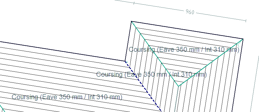
Inserts the coursing dimension onto the roof model after tiles have been installed using the coursing methiod. Set the height of the course dimension text and also the information to be displayed on the roof plan.
For example – Coursing (Eave ###E mm / Int ###I mm) would insert Coursing (Eave 310mm / Int 349mm) on the drawing as shown below.

 Roof/Wall Plane Areas
Inserts individual roof or wall plane areas. These will be printed on the roof/wall report.
The Suffix can be set to suit the situation – you do this under Set-Up > Preference Settings > Dimension Defaults.

 Project Wall
(On the Tools Pulldown Menu, but is the same function as Walls > Project Walls)
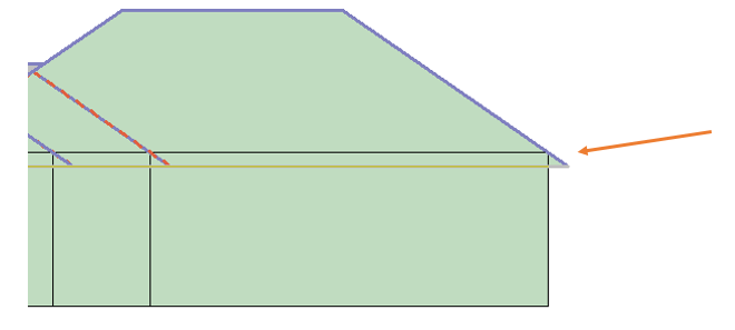
This command automatically projects the wall lines in the model down by an amount you enter, to the construction plane or selecting one wall at a time and project that to a specified height. It is a quick way to add walls to a roof model to improve appearance when viewed in ISO view.
After you select the command, you are prompted to enter the wall height. The default value is the eave height you have entered earlier. The original wall lines are modified to become the top of the wall then are projected down the height you want. Note that the original wall lines are deleted.
The following diagram shows an elevation view of a roof confirming where the walls are projected from.
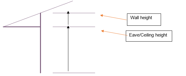
After you draw the wall lines, it is necessary to project them to their actual height. Walls may be projected up or down from the digitised wall lines. In order that the wall lines are compatible with the AppliCad roofing products, the wall lines you draw to create the perimeter for the roof geometry are at the top of the wall, if you have a roof in your model. If you do not have a roof in your model then the wall lines would typically be on the floor level (the CPL).
Select [Project Walls], a dialog box is displayed.
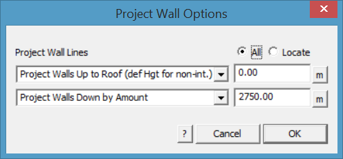
[Project Wall Lines] has multiple options that relate to whether the walls project up to the roof plane(s) and/or down to floor or ground level.
Project Walls Up
The [Project wall Up to Roof] simply takes all walls up to the under side of the roof planes. If a wall line extends beyond the perimeter of the roof for any reason, you can set the wall height to extend to. You might use the Measure function [m] to establish the height of the eave line to set the correct height.
If the walls are to be projected to the whole roof, then select the [All] button. On occasion, it may be necessary to select the walls and roof planes separately then use the [Locate] button. The walls will stretch up to the slope of the underside of the roof plane. Note the option for when the walls do not intersect with a roof plane, you must define a project distance or height (def Hgt for non-int = define height for none intersecting walls).
A wall line that extends beyond the roof with the height defined to the height of the eave line.
With a pitched roof, the distance from the ceiling height to the underside of the rafter is automatically calculated and the wall top is projected to the roof. It is NOT the same height as the eave height. You may choose to adjust this if required.
You would typically use the height calculated. In the box displayed above, this is the actual wall height for an eave height of 3000 and a roof pitch of 30°. After you enter the height of the walls, the wall lines are projected down to construct the walls. Each wall comprises the boundary lines and a plane entity.
![]()
Hint : It is a good idea to change your view to isometric at this stage so you can more easily see the 3D walls and select them to perform operations on later – use the function View > Isometric.
Project Walls Down
The second options relate to projecting down (if required). [Project Walls Down by Amount] allows you to set the exact amount down or [Project Walls Down to RL (Z Hgt)] projects down to the CPL.

Note the option for when the walls do not intersect with a roof plane, you must define a project down distance (def Hgt for non-int = define height for none intersecting walls).
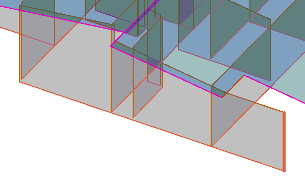
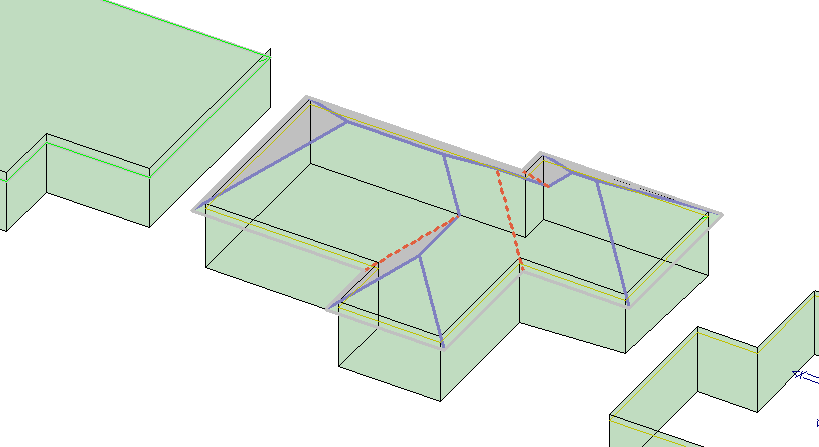
The wall lines are automatically tagged as Wall-Top, Wall-Base and Wall-Corner. These identifiers then define the type of flashing imposed on each line type. The following shows walls projected without the roof.
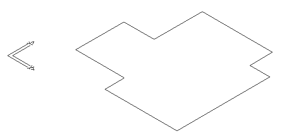
Walls before Project
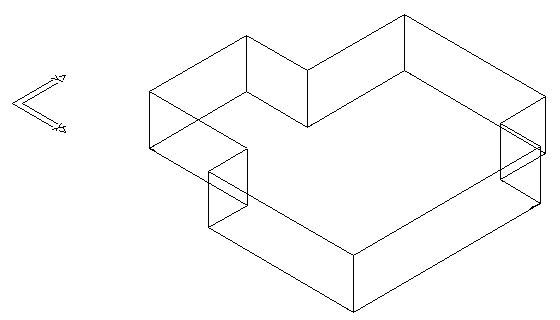
Walls after Projecting down to the specified height
Walls may be inserted on a sloping site too by projecting down to the RL.
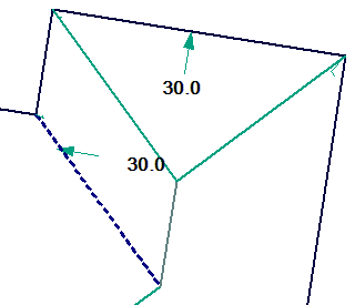
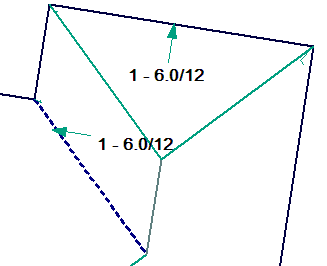
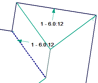
 Show Pitches
This command automatically displays the storey and the pitch/slope on each roof plane in the model. These labels disappear after a repaint.
The following diagram shows a roof where the roof planes have a 27.5 degree pitch. There are options to show the storey number and the direction of fall (down the roof) or not, as required, and these are set under Set-up > Dimension Defaults.


Roof Wizard only shows pitches for roof planes that are turned on. Also, it doesn’t try to dimension non-roof planes.
Tools Change
 Cha-LineType
[Tools > Change Entity > Line Type]
 This command allows you to change the line type or category to another line-type or to nothing. The command may also be accessed by simply pointing the cursor at a line and double clicking the mouse.
For modelling and estimation purposes, each line is given a line type automatically. This option allows you to change individual lines or groups of lines on a line by line basis. For example, the software automatically assigns the lowest point of the roof to be an eave, you may wish to install box gutter. In that case you will change the line type to Box-Gutter.
This function may also be activated by a double click of the left mouse button on the line.
After you select the command, the following dialog box is displayed, listing the different line type categories available.
You then select one of the line types. Crosshairs will appear and you simply select the lines that you would like to change to that line type. By doing so, the tag will change and the colour of the line may change and the style of the line may change to whatever you have defined in the Tools > Set Line Style command. You can use Verify on each line to see what the tag actually is, or you can use the Show button in the Flashings dialog.
Once you double-click on one line, you can then go and select other lines of the same type. The command stays in the loop until finished which makes it much faster to use.
The table below describes the menu item, the tag the system assigns, and how the flashing is reported.
| Line Type | Tag | Reported Flashing |
| None | NONE | Ignored |
| Ridge | RIDGE | Reports ridge flashing |
| Valley | VALLEY | Reports valley flashing |
| Hip | HIP | Reports hip flashing |
| Fascia&Gutter | FASCIA | Reports both fascia and gutter. |
| Gable | GABLE | Reports both barge and fascia flashings. |
| Fascia-Barge | FASCIA-BARGE | Only reports fascia as barge flashing. |
| Fascia-Only | FASCIA-ONLY | Only reports fascia flashing. |
| Gutter-Only | GUTTER-ONLY | Only reports gutter flashing. |
| Barge-Only | BARGE-ONLY | Only reports barge flashing. |
| Apron | APRON | Only reports fascia flashing. |
| Tuck-Under | TUCK-UNDER | Ignored |
| Box-Gutter | BOX-GUTTER | Only reports as a box gutter |
| Step | STEP | Reports the step flashing |
| Monoridge | MONORIDGE | Reports monoridge tiles |
| Purlin | BATTEN | Reports batten or purlin |
| Purlin2 | BATTEN2 | Reports alternate batten or purlin |
| Headwall | HEADWALL | Reports headwall flashing |
| User 1 | User Defined | Reports as defined by the operator |
| User 2 | User Defined | Reports as defined by the operator |
| User 3 | User Defined | Reports as defined by the operator |
| User 4 | User Defined | Reports as defined by the operator |
| Drawing Entity | DRAWINGLINE | Will appear on your drawings but will not affect the material or labour estimate. This may also be applied to other graphical elements that you add to a model, not part of the model, such as descriptive text, and you need them to appear on the report (refer to example below). |
| Wall-Base | WALL-BASE | Reports wall base flashing |
| Wall-Top | WALL-TOP | Reports wall top flashing |
| Wall-Corner | WALL-CORNER | Reports wall corner flashing |
| Window-Head | WINDOW-HEAD | Reports window head flashing |
| Window-Sill | WINDOW-SILL | Reports window sill flashing |
| Window-Edge | WINDOW-EDGE | Reports window edge flashing |
| Door-Head | DOOR-HEAD | Reports door head flashing |
| Door-Edge | DOOR-EDGE | Reports door edge flashing |

An example of the use of [Drawing Entity] – changing the text so that the text becomes part of standard annotation, and copying extra lines to provide for optional extras on a job.
The User defined line types are defined under the Set-Up > Preference Settings > System Preferences.
 Cha-PlaneType
[Tools > Change Entity > Plane Type]

This command allows you to change the type of plane to a Roof Plane, Wall Plane or to None. Changing to None has the effect of the system not recognizing that plane as a roof plane in its calculations.
Cha-PlaneMat
[Tools > Change Entity > Plane Material]

This command allows you to change the material assigned to a roof plane. By selecting this command you are prompted with another menu with the options, Tiles, Shingles, Shakes, Metal or Low-Slope. Select the material that you want o change you plane to and then select the planes required to be changed.
This function may also be activated by a double click of the left mouse button on the plane.
You can determine the roof plane material by selecting the Verify command from the main menu, then selecting a plane. You can then read the tags on the plane. The plane material is stored as a ROOFMAT tag.
 Cha-Storey
[Tools > Change Entity > Storey]
This command allows you to change the storey of one or more roof planes. After selecting the command, you then select the planes you want to change. You are then prompted to enter the new storey. Any line work attached to the planes is changed to that new storey also. The storey number allows different pat scales to be applied to different levels of the roof -typically, installers get paid more as they get further from the ground (but not always).
Tools > Check
 Check Model
This option takes you to a set of tools for automatically checking the model data structure and overall integrity. This is extremely useful if you had attempted a large number of modifications and undo and redo operations on a model that might have affected the model data structure in any negative way. The results are reported in the prompt area of the screen.

Check-Model-Integrity checks the integrity of the CAD model of your roof and deletes errant data. The resukts are displayed in the prompt area should any elements be deleted. The required outcome is nothing deleted which confirms that the model structure is sound. Note – You cannot perform an Undo on anything the system deletes using this command.

Display-Coincident-Lines checks for lines that share the same position in space. This would cause additional flashing materials to be ordered unnecessarily. (refer to Link Panes below)
Merge-CoLinear-Lines merges lines that have been identified as being co-linear.
Show-CoPlanar-Roof-Planes displays roof planes that are exactly across one another in space.
Delete-Free-Lines-Points automatically deletes all free lines and points not associated with a roof plane.
Link-Planes removes coincident lines between roof planes. These are created on occasions when major modifications or additions to the roof geometry are made by the user. This cleans these up.
CAUTION! The following functions are not for general use.
Show-EleList This function is for the use of system administrators to help debug models, perhaps models that are corrupt. The EleList shows all CAD entities that are related – for example, two points define a line, and multiple lines will define a plane outline. The points, lines and planes are related and connected to each other in a list. This function displays the related entities. It is hierachical from the starting entity – select the point to show the lines for example.
Show-AppList This function is for the use of system administrators to help debug models, perhaps models that are corrupt. The AppList shows all Roof Wizard elements (displayed as lines and planes) that are related – for example, batten lines are applied to a roof plane and become part of the application list for the plane. The lines and planes are related and connected to each other in a list. This function displays the related entities.
Delete-Element allows the System Administrator to delete elements, but must be used with extreme caution as anything deleted can break the structure that allows cuttinglists, costing, labour etc to be extracted. Undo will allow you to back up if you have deleted anything by mistake.
Delete-Associated allows the System Administrator to delete elements and all associated elements in the list. Undo will allow you to back up if you have deleted anything by mistake.
Find-Text Allows the user to find any bit of text, such as panel or flashing annotation on a large model. If you can’t find the text to change it in any way or delete it, then select the option, define the exact wording of the text and the software finds it, flashes it at you so you can do what you have to do to it.

Note – all the menu options in this dialog are continuous strings, which is what is required for options to be included in command strings such as the Pulldown menus and function keys etc.
 Tools > Measure
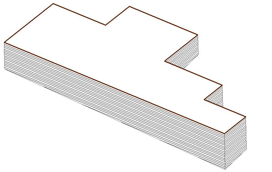
The measure commands allow you to measure a variety of geometric properties in the model. The most used functions are in the Icon Menu for ease of use. The Pulldown menu has the comprehensive list of options.
Distance b/t (between) 2 points
This command reports the distance between 2 points you locate, typically with the middle mouse button so that you are ‘snapping’ exactly to the point.
The dialog displays the Model coordinates with respect to the Absolute origin and the construction plane (CPL) coordinates with respect to the CPL origin. For roofing, this will usually be the same origin as we have no need to change origins. The display shows the coordinates in X, Y and Z. It also shows the distance in each axis between the two points selected. This is a very handy command to use to measure the relative eave heights on two parts of the roof.
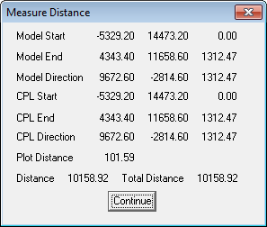
Entity Length
This command reports the length of a line or arc you select. The precision [number of decimal places] for measure length is determined by the defaults set in the CAD program – CAD > Defaults > Systems Settings > Configure.
Sum of Lengths
This command reports the length of a group of lines and arcs you select. You may use this to check the total length of an eave around a roof. The command aggregates the eave line lengths.
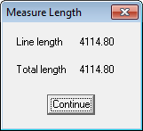
Area
This command reports the area of a plane (for example a roof or wall plane) you select.
Area and Perimeter
This command reports the area of a closed boundary you select. The command requires you to select the first line and then the successive list of connected lines is automatically traced. (ie instead of selecting a plane, you can select the lines that form the plane boundary).
Area b/t Points
This command reports the area of a shape you have digitised. In this case, you digitise a series of points which define the corners of the shape, typically using the middle button so that you ‘snap’ exactly to the required point.
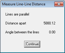
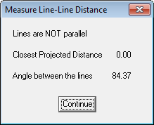
Distance b/t Parallel Lines
This command reports the distance between two lines if they are parallel and the angle between if they are not.
Angle
This command lets you measure the angle given 3 points. Select the points using the middle mouse ‘snap’ feature to ensure that you are EXACTLY on the line end point.
Bearing
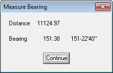
This command lets you measure the bearing given 2 points relative to North (up the page) and also the distance between the two points.
Rainfall Capture
(Pulldown Only)
[Tools > Measure > Rainfall Capture]
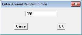
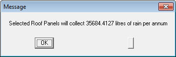
This command provides the ability to determine the amount of rainfall that may be captured from the roof based on average, or specific rainfall. You select the roof planes that will contribute to the catchment and the rainfall for the period, say 240mm in a year – these planes are highlighted, then confirm your selection and then input the rainfall for the period in mm or inches depending on your units defined under preferences. If you wish to calculate rainfall for a shorter period, simply input the rainfall for that period. The result will be displayed as shown below.
Mass Calculations
(Pulldown Only)
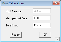
This command allows you to calculate the mass for the roof based on the roof area and a mass per unit area.
 Measure Pitch Aerial Image
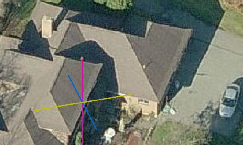
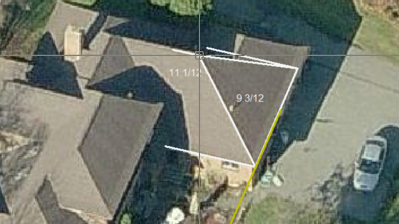
This function allows the operator to import an oblique aerial image and by placing the 3D cursor on a corner, typically an eave corner and aligning the X,Y,Z axes to the image, the pitch of the hip or gable end can be determined. The resultant pitch may be used to create a 2D model or a 3D model of your roof.
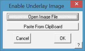
First, import the image. To do this select the Construct Roof > Track Outline function; and select the [Enable Underlay Image] button (refer below for more detail) to place the image on screen from a file (usually saved into the …\Roof Wizard\User folder) or from the image captured in the Windows clipboard using the Windows utility ‘Snipping Tool’ or something similar.
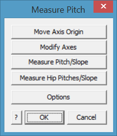
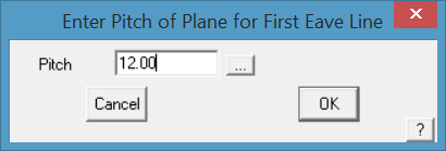
Then select the Measure Pitch tool button. The following dialog box is displayed and the 3D axis icon is placed at the model origin.

Typically the 3 axis indicator comes on screen at an apparent random location (in fact at the work space origin (X,Y,Z = 0), which may not match the current image).
The button [Move Axis Origin] places the 3D axis icon on the desired corner of the roof, typically at an eave corner.
The [Modify Axes] aligns the respective axes with the roof edges in the image.
You can re-do this iteratively until you are happy with the placement. Right click [Cancel] to finish placement.
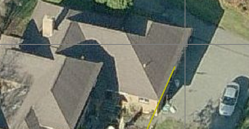
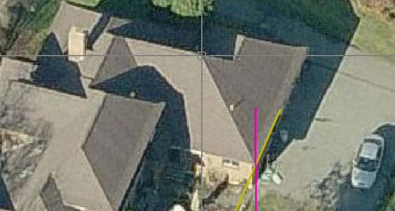
Measure Gable Pitch/Slope
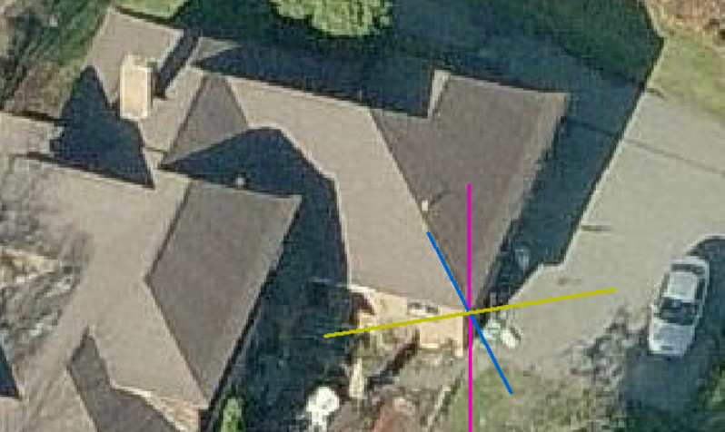
Next, select the measurement option that suits your job. The [Measure Pitch/Slope] options measure an angle in the selected construction plane or CPL as indicated by the axis indicators set under [Options] described below.
Next you will need to align each axis with an ‘edge’ in the image. Use the [Modify Axes] button, you will be prompted to locate each axis is turn, X, Y and Z to align the axis indicators with the view of the roof.
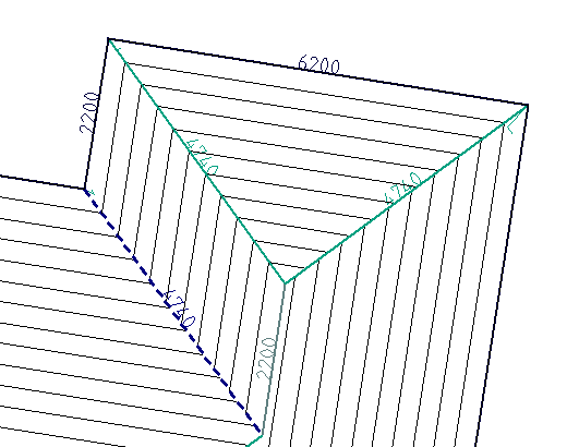
This function would typically be used to measure the pitch or slope of a gable roof as shown below.
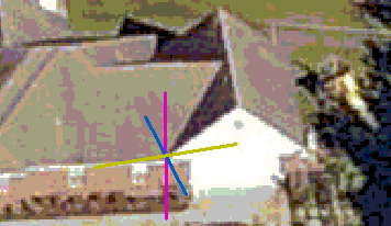
- Move Axis Origin (to align with a corner of the roof)
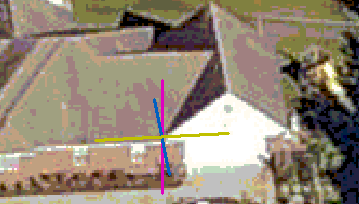
- Modify Axes (to align with image of the roof.
- Measure Pitch/Slope, select plane to measure pitch in (Typically XZ) and click a point in the line of the gable to measure the pitch (here the pitch is shown in degrees). You may also use slope.
If the pitch text is too small or difficult to read, use the [Options] button to chage colour and size of text. You may also change the size and colour of the individual axes as well, so as to make the information easier to read.
Measure Pitch Options
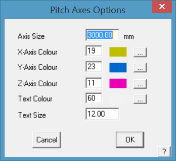
Axis Size sets the size of the lines on sceen representing the X,Y,Z axes.
Axis Colour sets the colour of each axis line from the CAD colour pallet.
Text Colour sets the colour of the text for the pitch dimension. Select a colour that contracts well with the underlay image.
Text Size sets the size of the text on screen, select a number that is large enough to read clearly.
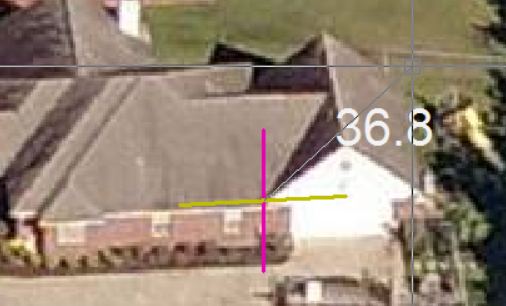
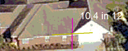
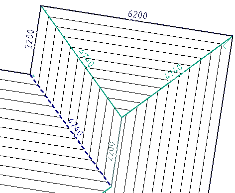
Measure Hip Pitch/Slope
The Measure Hip Pitch/Slope prompts for the other end of the hip from the 3D Axes origin, then the apex point of the hip. The hip end is drawn and the pitch of each plane displayed.
This function can be used to measure the pitch of hips and gables.
Placement of the 3D Axes origin point with [Move Axis Origin] button.
Left click on the corner of the hip to locate the position of the new axes origin. Align to image with [Modify Axes] button and you will be prompted for the new X axis, new Y axis and new Z axis (read the prompts).
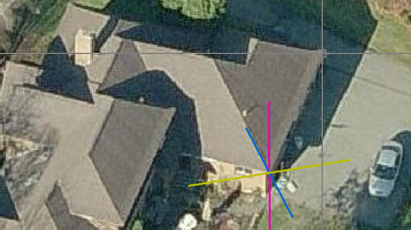
New X axis
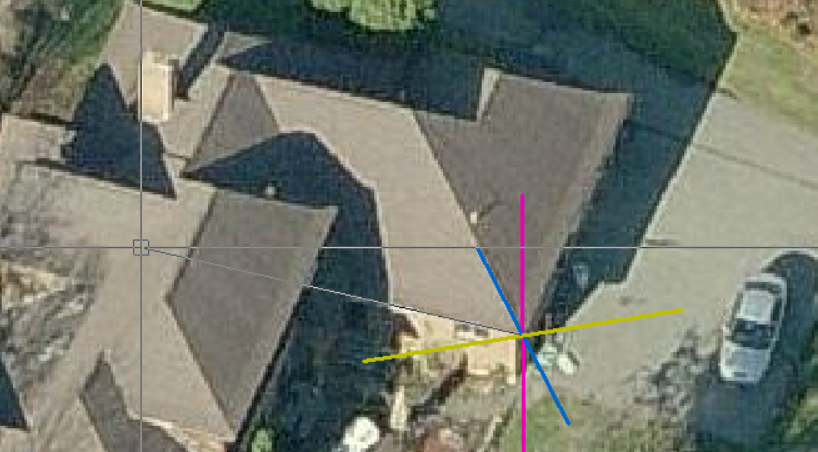
New Y axis, and the new Z axis will usually be in the line of the current Z, straight up the screen. This may vary slightly depending on the image.
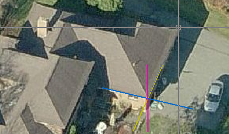
Now select Measure Pitches/Slope and read the propmpts. You will be prompted for the Reference Axis (Base of Hip). Then the axis to measure pitch towards (usually Z axis).
Then indicate the other end of the hip end.
And next the approximate hip apex point.
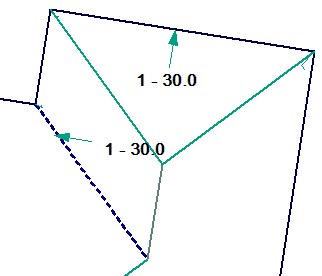
The hip is drawn and the pitches displayed.You may reselect the apex repeatedly to improve the accuracy.
The result will be in degrees, slope or percentage as set in the Set-Up > System Preferences.
 Calc Adjacent Pitch
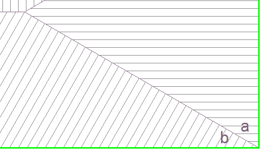
The operator is prompted to indicate pitch of roof plane ‘a’ and digitises the eave lines and the software calculates the pitch of ‘b’.
Set Display
This command allows you to mask different categories of information from your current display as well as by storey. When you click the command, the Display settings dialog box is displayed.

Each button is a yes/no toggle which simply turns that information on or off. If you select the [On-All] or [Off-All] buttons then all settings are changed to Yes and No respectively. [Set All Off] and [Set All On] will turn all fields on or off for the storey selected. When you click [OK], the screen is repainted with the relevant information.
You can nominate the storey to effect by either clicking on the right hand storey button (Second à above) or by clicking one of the storey buttons at the top left hand corner.
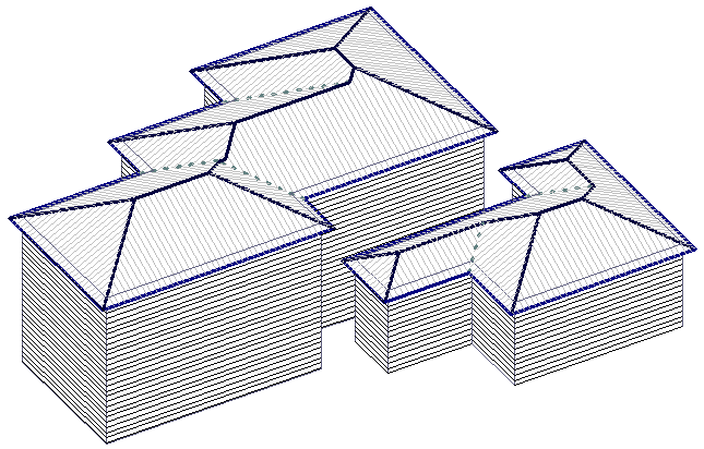
Consider the following diagrams that show a two storey roof.

All layers displayed Second storey walls and roof turned off

First storey walls and roof turned off First and second storey walls turned off
 Export Image from Screen
This function captures whatever you see in the workspace area of the screen and creates a bitmap file that is saved to the \User folder. The operator is prompted for a file name and file type, with appropriate controls for each file type. A large number of file types are supported.

This tool will prove very useful for users who are modelling roofs from aerial imagery and providing the quantities to their customers. Anything can be modelled on screen and simply output using this tool to a Microsoft Word or Excel file.
When outputing to an “imagery report,” software allows the user to preview all images that will be placed into the report prior to actually going through the process of report creation. The resultant image file may be used for all manner of purposes from illustrating a report or an installation guide. It is the best way to get your roof model or drawing into a Word or Excel report template. Refer to how this is done, Reporting > Creating Word Template.
Plot
The Tools > Plot Wizard command allows you to quickly create a plot as Vertical or Horizontal and send it to your Windows printer. You also have the option to place the drawing form or get the command to fit the drawing to the paper.

It includes a Plot Wizard option that provides for various commands to generate a plot of your roof automatically fitting to various page or sheet sizes. The operator can also insert a drawing border, plot in colour or a ‘hidden lines’ view where lines behind are blanked out.

Either of the other options requires the operator to select and set the plot extents. The paper size selected is A4 if your Set-Up > Preference Settings > System Preferences > Units are set metric, or Letter size if the units are set to English or Imperial.
Vertical
This command lets you place the drawing form (A4 or letter size) over an area of the drawing for plotting in a vertical orientation.
Click Vertical, and the Windows Print dialog box is displayed.

After you click [OK], an image of the drawing page is dragged on your cursor. You can then see the relative extent of your model and the page. Locate the bottom left hand corner of the page by clicking the left mouse button, then the plot is sent to your printer.
![]()
Note: You may need to adjust your screen display with the Zoom commands and/or the View > Plot-Scale command so you can see the dragged page on screen, as well as fitting your model to the page.
You will find automated printing from the Reporting > Supply-Only, Supply+Install dialog box as well as the Drawings command. You can perform advanced printing using the Drawing > Plot > Screen > Scaled, or the Drawing > Plot > Compose commands.
Horizontal
This command lets you place the drawing form (A4 or letter size) over an area of the drawing for plotting in a horizontal orientation.
Click Horizontal, and the Windows Print dialog box is displayed.
After you click [OK], an image of the drawing page is dragged on your cursor. You can then see the relative extent of your model and the page. Locate the bottom left hand corner of the page by clicking the left mouse button, then the plot is sent to your printer.
![]()
Note: You may need to adjust your screen display with the Zoom commands and/or the View > Plot-Scale command so you can see the dragged page on screen, as well as fitting your model to the page.
You will find automated printing from the Reporting > Supply-Only, Supply+Install dialog box as well as the Drawings command. You can perform advanced printing using the Drawing > Plot > Screen > Scaled, or the Drawing > Plot > Compose commands.
Fit-Vertical
This command automatically fits the drawing to your page (A4 or letter size) in a vertical orientation.
Click Fit-Vertical, the Windows Print dialog box is displayed. After you click [OK], the plot is sent to your printer.
![]()
Note: You may need to adjust your screen display with the Zoom commands and/or the View > Plot-Scale command so you can see the dragged page on screen, as well as fitting your model to the page.
You will find automated printing from the Reporting > Supply-Only, Supply+Install dialog box as well as the Drawings command. You can perform advanced printing using the Drawing > Plot > Screen > Scaled, or the Drawing > Plot > Compose commands.
Fit-Horizontal
This command automatically fits the drawing to your page (A4 or letter size) in a horizontal orientation.
Click Fit-Horizontal, the Windows Print dialog box is displayed. After you click [OK], the plot is sent to your printer.
![]()
Note: You may need to adjust your screen display with the Zoom commands and/or the View > Plot-Scale command so you can see the dragged page on screen, as well as fitting your model to the page.
You will find automated printing from the Reporting > Supply-Only, Supply+Install dialog box as well as the Drawings command. You can perform advanced printing using the Drawing > Plot > Screen > Scaled, or the Drawing > Plot > Compose commands.
 Tally-Quantities
This command automatically reports the geometric lengths and area of the roof and roof lines.
You also are told the number of shell ends as well as the number of apexes. For convenience, the values are differentiated based on storey and type of roof material.
After you click this command, the Summary of Roof Quantities dialog box is displayed:
Here you can see a complete breakdown of the roof geometry, defined by areas, lengths and the count of discrete positions. The above dialog box shows a combined quantity, whereas you can separate quantities based on materials. By selecting values from the drop down box, you can get quantities for Tiles, Shingle, Shakes, Metal and Flat roofs separately.


Roof Volume cu m The total volume of the roof in cubic metres or feet
Roof area The total area of roof planes in the model of the given material
Curve quality area The area of curved roofing in the model
Ridge length The total length of ridges
Mono Ridge The total length of mono-ridge
Hip length The total length of hips
Valley length The total length of valleys
Eave length The total length of eaves
Gutter length The total length of gutters
Barge length The total length of barges
Fascia as barge The total length of barge covered by fascia
Apron length The total length of apron lines
Box gutter The total length of box gutter
Step length The total length of step lines
Shell ends The number of hip ends (bottom of hip lines connected to 2 eave lines)
Hip apexes The number of points at the top of 2 intersecting hips
Barge apexes The number of points at the top of 2 intersecting barge (rake) lines
Barge top internal/external The number of points at the top of barge lines connected to an eave
Barge bottom (left and right) The number of points at the bottom of a barge line connected to an eave line (eg at the bottom of a gable end)
Free barge top (left and right) The number of points at the top of barge lines not connected to an eave.
Free barge bottom (left and right) The number of points at the bottom of a barge line, not connected to an eave (eg the bottom of a gable on a dormer)
Stop ends (left and right) The number of free ends on an eave / gutter line (eg when an eave connects to a barge)
Corners The number of corners of the particular type in eave lines.
The Mono-Ridge and Tuck-Under line-types, while not used for flashing generation within the software, has been added to the Roof Quantity Summary dialog to allow users to inspect the total length and also select the […] button which highlights all instances of the line within the model.
A [Change Line Type] button has been provided so that you can edit the line type without exiting the Tally dialog to adjust/repair mis-labelled lines.

The following diagrams help describe the different point objects.


The button Show Un-Tallied displays all items not accounted for in the roof model. All entities that are part of the model and not tallied are flashed on screen. This is usually due to the item not correctly specified ot not part of the roof model.
If you wish to export this information to another computer system you can click the Export CSV button which will write a comma separated value file automatically. It will output all values for all 10 storeys as well as a table breaking down the roof area based on pitch and area.
If you had generated offset roof planes using Estimate > Offset-Roof, the area of the offset roof planes will also be displayed.
You can separate the areas based on roof materials or get a combined set of values depending on the setting in the drop down box.

The print button prints the quantities as reported in this dialog box.
Note: If Stage Manager is turned on (Set-Up > System Preferences) and being used (Cover > Stage Manager), the tally shows what stage is being reported on.

 Verify Entity
This command reports all the CAD data and information about an entity you select.
The reported information differs depending on the type of entity you have selected.
In the above examples, you will see the tag written on the line making it a RIDGE, and the tag on the plane entity which makes it a PLANE.
Z height of a line.

Verify Command 1 – Verifying a line
The model start and model end points are shown for the selected line and the X,Y,Z coordinates for each point is displayed. From this information the Z height of a line, which would be the height of that line above the job datum is displayed. If you were trying to figure the eave height of a roof edge for example, the Z of the start and end points would be the eave height.

Verify Command 2 – Verifying a plane
When you select a line the model point coordinates are displayed for the start of the line and the end of the line in the form of X, Y, Z. This is a very useful feature as it will display the actual height of the line relative to the CPL (construction plane) which usually represents the ground level. In effect then, it is giving you the eave height if you select an eave line where the Z height is the eave height.
Wizards
The Wizards are a series of automated tools that help speed up certain processes, or keeps you to a specific process using the AppliCad functions..
Plot Wizard
 The Plot Wizard option that provides for various commands to generate a plot of your roof automatically fitting to various page or sheet sizes. The function may also be selected from the Check > Plot Wizard icon. The operator can also insert a drawing border, plot in colour or a ‘hidden lines’ view where lines behind are blanked out.
All standard printer sheet sizes are provided for in ‘Paper Size’.


Using Tools > Plot you can also select a random area of the job to be printed in vertical or horizontal aspect.

Either of the other options (displayed above) requires the operator to select and set the plot extents. The paper size selected is A4 if your Set-Up > Preference Settings > System Preferences > Units are set metric, or Letter size if the units are set to English or Imperial.
To fit more of the desired area onto the sheet, change the plot scale up and down as required – View > Plot Scale.
A plot scale of say 1:100 will capture this much of the job:

And 1:50 will capture this much.

Bill of Quantities
This Wizard takes you into the Supply and Install dialog via the customer and job details dialogs to complete a client proposal based on a previously supplied Bill of Quantities, and create the usual reports and details ion your standard form templates.
Full Job
This takes the user through the list of the steps typically employed to complete a client proposal in the order that you would use from start to finish. Us it as a guide to ensure that you complete all steps correctly.
Visualisation
The visualisation option allows you to go into a perspective view of your model, and navigate up, down and around the model, as if you were actually at street level, to view and check it.


In combination with the dynamic rotate (using the middle mouse button with the CTRL key depressed), you can check out your model from every side, up and down – and scroll wheel zoom in and out.
![]()
Note: Depending on how much you move the view about, you may have to use View > Reset View to get it back to the standard ISOmetric view.
Trace Roof
This wizard uses a four step approach to guide you through digitising an image or PDF document starting with selecting the image file or pasting from the clipboard. It includes the step to scale the image to true size thus ensuring that the final model is correct. It works the same as the Construct Roof > Track Outline function using an Underlay image described elsewhere in this manual.
 Dimension Default Settings
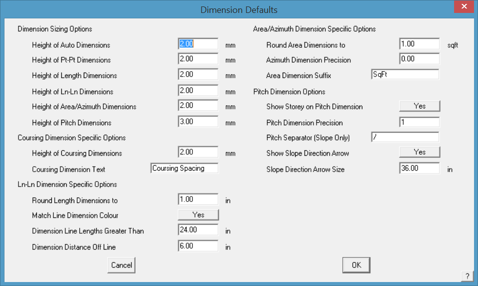
After selecting the Toofl > Dim Defaults icon, the Dimension defaults dialog is displayed.
![]()
Note: Typically, the font used to annotate roof planes and drawings is the font defined under CAD > Defaults > Text Defaults. As these may change from user to user, it is suggested that a text file called Fontfile.dat be created and saved in the User folder, thus ‘locking-in’ the required font style for each user. The font used on the roof plan for annotation such as area, azimuth etc will then be determined by the font defined in the Fontfile.dat. True type fonts will be listed by their name only (such Arial or Calibri) and the CAD fonts by the name and the extension (such as HELV.FON for Helvetica font or ISO.FON for CAD ISO font). If no font file exists (it must be created by the user) then the CAD text default settings will be used.
Dimension Sizing Options
These options allow you to alter the size of dimensions for the four different methods. You will see the effect on screen and on the printed drawings.
Coursing Dimension Specific Options
Set the height of the course dimension text and also the information to be displayed on the roof plan. For example – Coursing (Eave ###E mm / Int ###I mm) would insert Coursing (Eave 350mm / Int 310mm) on the drawing as shown below.
Ln-Ln Dimension Specific Options
Round Length Dimensions to .. sets the rounding up of the dimension number drawn on the roof drawing – in the example ±10mm.
Match Line Dimension Colour changes the dimension colour to be the same as that set for the line making it easier to associate a dimension with the matching line. If set to no, the default settings for dimension are used.
Dimension line Lengths Greater Than allows the operator to set how short the shortest lines to be dimensioned will be. Anything shorter than the specified length will not be dimensioned. This takes the clutter out of the drawing by not dimensioning lines that may not be important.
Dimension Distance Off Line sets the distance the dimension is to offset from the associated line – roof plan on the left is set to 0; roof plan on the right is set to 100mm.
![]()
Note: Be careful switching between metric and imperial units as this can have a detrimental effect on settings such as arrow size – 100mm in metric becomes a 100” in imperial.
Without offest from the referenced line.
With offset from line set to required distance.
Azimuth/Area Dimension Specific Options
Round Area Dimensions to sets the rounding up of the area dimension number drawn on the roof drawing – in the example ±1sqm.
Azimuth Dimension Precision sets how many places after the decimal point.
Area Dimension Suffix adds a suffix to the area dimension such as SqFt or SqM.
Pitch Dimension Specific Options
Show Storey on Pitch Dimension adds the roof storey to the pitch dimension drawn on the roof plan. Used in conjunction with the precision, in this case one decimal place.
Pitch Dimension Precision sets how many places after the decimal point. Our example displays one decimal place.
Pitch Searator (Slope Only) sets the separator character btween the numbers indicating the slope of the roof. Typically a colon as shown, but may be a slash.
Show Slope Arrow Direction – Y/N Slope direction arrow may or may not be displayed.
Slope Direction Arrow Size sets the size of the arrow. Since we model the roof geometry at full size, the arrow would need to be about 1000mm as shown above (or the equivalent in feet and inches).
![]()
Note: Be careful switching between metric and imperial units as this can have a detrimental effect on settings such as arrow size – 1000mm arrow in metric becomes a 1000” arrow in imperial.
Define Report Notes
(Pulldown menu only)
This option allows the operator to define a series of standard notes that may be called as required when the report is generated.
- You define basic note structures (templates of Notes to be used per report) using this function, or you can just type them in freehand when you enter them from the Supply&Install dialog box. These notes entered free-hand are not saved. The notes created here may be re-called as required.

Add button adds a new report note. Select the Add button and the edit dialog is displayed. Add the required text and select [OK]. The note information is written to a text file called Notes.dat.

Edit button allows you to edit the content of the note.
Delete button deletes a previously defined note.
All modern-day reports are intended to use the ###QQNote structure, which allows for up to 1997characters of notes for each report. They are stored in an array of 500 in size, which means you could have notes for 500 reports. Any reports after that would not be able to use Notes. Should be plenty!
The information is written to a text file called Notes.dat and is in the form shown below. It may be quicker to create the notes in Wordpad or Notepad following this structure. The Notes.dat file must be saved in the ..\User folder and is in the form as shown below:
GST Included
 All prices quoted on this quotation contain GST (10%).
 <END>
 GST Excluded
 All prices quoted on this quotation are exclusive of GST (10%).
 <END>
 No CleanUp Included
 Rubbish removal and general site cleanup are not included in this quotation. For a separate quotation on site cleanup, or to have this included on the quotation, please contact us.
 <END>
 CleanUp Included
 This quotation also includes all cleanup of rubbish produced on the site, as well as the removal of this rubbish.
 <END>
 Standard Inclusions
 All standard inclusions apply, including the following: -
 <END>
Define Print Options
(Pulldown menu only)
This option allows you to pre-set the reports that you usually print for a regular quotation or estimate.

The order of these standard reports is set – do not change the order. If you wish to add a new template, add it to the bottom of the list.
Define Drawing Options
Set which of your report templates are automatically set to print in teh same manner as for reports.
Edit User Templates
Select the report from the list that you wish to edit the content of.

If it is a CAD report or drawing, the sub-figure in Roof Wizard will be opened and allow you to change as required. If it is a MS Word template, then MS Word opens up with the template and allows you to edit as reqiured. If you wish to add a new template, select the [Add/Edit] button and you will be prompted for the report to add.

Modify Text
Takes you to the text modify options
Insert Key Text Insert Key Text Strings that automatically creates the report
Insert Text Insert regular text
Insert Co. Logo Inserts your company logo onto a report template
Text Defaults Sets the default text appearance when inserted
Change Change text appearance after placement
Move Moves the text to required location on template
Copy Copies existing text on the template
Edit Text Edits existing text on the template
Delete Deletes text from your template
Make Text Float Floats text over other CAD entities in the report, so as not to obscure text in the report.
Set Text Field Width Sets the number of characters in each field
Flip Text Direction allows text to be “mirrored”. This function is useful to assist in the modification of text in ISO views of your model, such as Wall Panel text, to improve readability.
Set Text Field Width
Accessed from the Pulldown menu, this function allows you to set the width of the text in a CAD Report. If this is not set correctly, especially for something like QQNotes in the CAD template, then the note is compressed into a small space so it is not legible or hangs off the edge of the page.

Select Tools > More > Set Text Field Width and follow the prompts to first select the Key Text string text to be set, the set the first and last point to define the width of the text field.


Create Flat Pattern
The Flat-Pat command is used to facilitate the unfolding of surfaces drawn to represent special roof features such as domes, spires or tapered gutters. Users can take a three dimensional model and unfold its surfaces to produce cutting templates or flat patterns for manufacturing. It also provides allowances to plate thickness and neutral axis depth, so that accurate repeatable results can be obtained. Flat planes, ruled surfaces and cylinders can be unfolded. A tutorial on the practical use of this function is described here.
The Create Flat Pattern > Rul-Sur command can be used to unfold general ruled surfaces apart from cylinders. Some reservations apply when using this option for the following reasons:
There is no provision for bend allowance with the Flat-Pat Rul-Sur command. The model to be unfolded will be understood to represent the neutral surface. This is fine when the material is relatively thin compared to its extent (e.g. tapered gutters etc.)
Ruled surface entities are constructed by generating rulings at equal spacing along two generator curves (the section curve of a dome for example). Sometimes, the surface will be twisted as well as bent. A twisted surface cannot be unfolded without also drawing or stretching the material. The Rul-Sur command still produces a result, but the outline created is an approximation. Some ruled surfaces are not twisted. If one of the generators is a point, the surface will not be twisted. If the two generators are always parallel the surface will not be twisted. This is the case if one generator curve is a scaled, translated (but not rotated) copy of the other.

When selected, the system prompts for the location of the ruled surface near the edge to unfold.
1 Select the ruled surface by one of its ‘straight’ edges at the end to start the unfold process from.
After selection, the system prompts you to locate the position to unfold the surface.
2 Locate a point on the CPL to use as the corner of the unfolded surface.
Next, locate another point to indicate the direction to unfold the surface.
Surface Flat-Pat Ru-Sur
D1 – Locate ruled surface
D2 – Position to unfold surface
D3 – Direction to unfold surface
Locate a point to show the direction to unfold the surface. The surface will be unfolded in the x-positive or x-negative direction depending on the placement of the located point.
When unfolded, the flat pattern outline is represented by two lines and two curves. There is no opportunity to rotate other entities that may depend from the ruled surface. If the desired flat pattern includes a series of planes and unfolded ruled surfaces (e.g. a square-round duct transition) then the separate unfolded surfaces and planes must be separately translated and rotated to bring them together as a single pattern.