Track Outline
Track Outline
The creation of the outline or perimeter from which the roof geometry is created may be developed by digitising or tracing an underlay image (aerial image or PDF of and Architect’s plan) or by ‘tracking’ the outline using actual measurements, or a combination of both. The outline can be a wall perimeter measurement (and eave overhang is added later) or an eave perimeter measurement (with zero overhang). It can result in a single plane roof or a complex fully hipped roof.
When you select the Track-Outline command, the software prompts whether you wish to start with a previous incomplete outline. This occurs so that you can recover if you made a mistake and cancelled before the outline you were defining was complete, or one of your perimeter measurements was incorrectly input. Instead of redoing the entire job, recover the outline and change the one line that was incorrect.
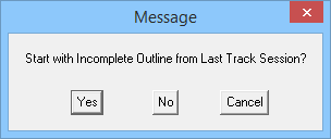
Selecting [Yes] takes you to where you left off. [No] takes you to the default start of the track process from the job origin (at X,Y coordinates of 0,0) and the Wall Direction and Distance dialog box is displayed.
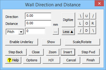
‘Full’ dialog display
This dialog has been designed to allow you to quickly and efficiently enter the outline of the wall or roof based on a variety of inputs.
The Track Outline dialog, along with many other larger and sometimes more complex dialog boxes, has two modes – a Full display and a Simple display. [More] and [Less] buttons to hide the less used functions of the software until you need them. This cleans the interface up and provides a simple user experience for first-time users.
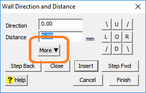
‘Simple’ dialog display
![]() Note: The dialog box shows two fields labelled as Direction and Distance. The direction is a cardinal bearing starting at 0o – UP the screen, clockwise through 180o – DOWN the screen, and back up to 0/360o. The distance simply relates to the length of the line defining the eave/wall.
Note: The dialog box shows two fields labelled as Direction and Distance. The direction is a cardinal bearing starting at 0o – UP the screen, clockwise through 180o – DOWN the screen, and back up to 0/360o. The distance simply relates to the length of the line defining the eave/wall.
The accelerator buttons on the right hand side, are predefined directions with the following values, based on up the screen being 0o:


![]()
Note: You can also use the letters U, D, L and R in the distance field to quickly get up, down, left and right directions. For example, you can enter R5000 or R5M in the distance field to get a eave/wall line length defined as right 5000.
You simply click the appropriate accelerator button, enter the distance and a new wall segment is drawn on the screen. You can enter a new wall by selecting the Enter key or clicking the Insert button.
If you make a mistake with a value, click the Stepback button. You can undo a Stepback operation by clicking the Stepforward button. You can step forward as many segments as you stepped back.
When you have finished locating the wall lines, click the Close button. This displays the Select the close method dialog which helps you select the type of close method you want from the current line end point to the first digitised point. This will then display the Close dialog box from which you select a close method. You are then returned to the Wall Direction and Distance dialog box.
Direction Option
The direction option is tied to the notion of Up, Down, Left and Right, but instead of using these you use a bearing angle as suggested above, up = 0° and down = 180° etc. This permits you to insert wall directions that are not square.
Distance
The distance is the length of the line in the direction specified and the units of measure are determined by the settings you have selected under Preferences – either metric or imperial units.
As a time saving device, enter the letter “U” for up, “D” for down, “L” for left or “R” for right, in front of the length of the wall or eave line required. Then click enter.
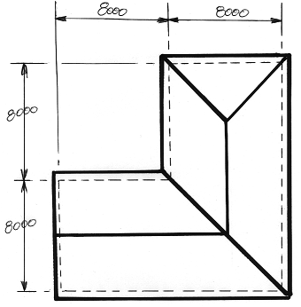
On this job, you could have typed in U8000 {Enter} R8000 {Enter} U8000 {Enter} R8000 {Enter} and then Close the outline as a Square. You may also simply type C (short-cut for close square){Enter} in the distance field on the dialogue. You can also input U8m indicating metres or 8000mm if you’re working in Metric.
Pitch/Radius/Bulge Option
The pitch button  is where the pitch is inserted and the units of measure for pitch are determined by the settings you have defined – degrees, slope (n:12) or percentage slope (% = n:100).
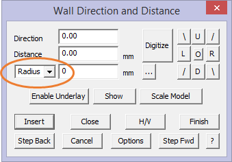
The drop down field offers alternate options for Radius which allows for the creation of a line whose length is determined by the chord length of an arc and Bulge. These situations occur when a so called ‘curved’ roof is to be covered with a metal panel or sheet that is rolled as a flat sheet and ‘walked’ onto the roof and fixed as it is installed. This is also known in some circles as a ‘sprung’ roof.
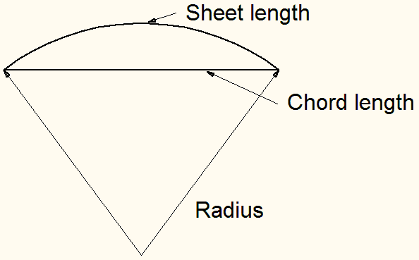
When Radius is displayed, the field next to Radius is the radius of the arc of the roof. When Pitch is displayed, the field next to Pitch is the pitch of the roof.
This allows a quick and easy way to create a rectangle that would be the roof area if the arc roof was pressed flat. Since the sheets are ordered this way (that is, as flat sheets), then this works perfectly.
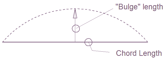
If you know the chord length (Distance) and the height of the ‘bulge’ then select that option and you will create the rectangle that would be the roof area if the arc roof was pressed flat as described above. Since the sheets are ordered this way (that is as flat sheets), then this works perfectly.

Refer to additional processes described here for measuring pitch from drone or third party images – Measure Roof Pitch from Image and Measure Roof Pitch from Oblique Image
Horizontal/Vertical Option
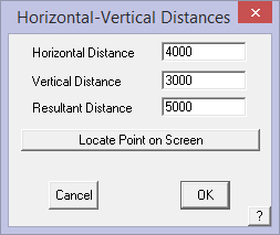
Sometines you only know the horizontal and vertical dimensions of a wall, rather than its direction and length which may be at an odd angle, you can use the given horizontal and vertical offsets and have the software calculate the length and directio for you – click the [Hor-Vert] button. The Horizontal-Vertical Distances dialog box is then displayed.
Horizontal distance The horizontal distance (offset) of the wall
Vertical distance The vertical distance (offset) of the wall.
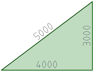
Resultant Distance This provides the opportunity for the software to do the trigonometry of a triangular situation where only two lengths are known and the software will figure the last length. If the 5000 and the 4000 length is known, the software will calculate and insert the 3000 length.
The software will flash a point indicating the likely two options for the intersection – either up or down in this case
You may also –
Locate Point on Screen to use an existing line end point as the basis of establishing the x and y (horizontal/vertical) offset from the job datum or origin. This will be automatically fill the H/V fields on this dialog. Then you insert anything different that you may need.
The wall line is drawn when you click [OK] and then you can continue entering the rest of the wall lines to complete the outline as described for Track Outline.
Use Field Measurements to Determine Pitch
The distance you enter in the Distance field may also be modified by the Pitch field. If this is zero, then the distance is assumed to be a horizontal measurement. The Pitch factor is used to reduce the distance to the horizontal distance. This is typically required when the roof measurements have been collected in the field and the person measuring is running the tape up the slope of the roof. You need to reduce this to the horizontal distance.
If you do not know the pitch but have ‘up and over’ or ridge to eave measurements, you can click the  button to the right of the pitch field to calculate the exact roof pitch.
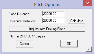
When you select [OK] on this dialog, the calculated roof pitch is inserted into the pitch field. You then use the combined pitch value and the up the slope dimension to calculate the length of the wall/eave line on the flat.
Step Back Allows the operator to back track in the event that the line digitised is incorrect.
Step Fwd Allows the operator to step forward in the event that the operator steps back too far.
Track Line Style Options
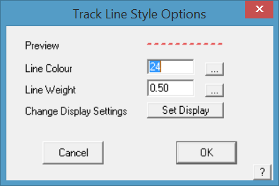
The [Options] button allows you to set the line style, colour and weight for the roof outline construction lines. This is especially useful if you are digitising over aerial images and PDF plans where the confusion of the background lines or image may make it difficult to see the roof features.
The Change Display Settings button takes you straight to the Tools > Set Display options. Saves you having to exit out of Track Outline and go to the Tools menus to set this.
Digitising and Tracking Outlines
The power of the Roof Wizard interface allows you to use a combination of techniques to create the various geometries that comprise roof and wall structures from which our client proposals and material/labour take-offs can be extracted. It allows you to generate a fully hipped 3D roof or single slope roof in 3D by digitising the entire perimeter outline of the roof or building.
Described in the preceding section is how the options operate when creating an outline by simply typing exact measurements into the dialog box – distance (length) and direction until the perimeter is closed.
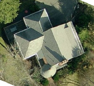
There are occasions when not all dimensions are provided. This is the time to use the underlay image and digitise the outline. The underlay image can be an aerial photograph or a scanned plan or the clipped area of an architect’s plan supplied as a PDF document.
There are three steps,
1 – Enable the image,
2 – Scale the image and work space and
3 – Start digitising.
First we need an image. These may include one of the following situations:
- You know most of the direction and length of the outline of the roof or wall linesusing existing CAD data (from an imported DXF file)
- digitise the ‘blue print’ of the roof plan on a digitising tablet and apply a scale factor
- digitise on a snapping grid by increments (the Grid command)
- from an image extracted from a satellite or aerial photograph service such as Google Earth, Bing or Pictometry
- import an uncompressed bitmap image of a roof plan (such as a BMP, JPG, TIF or PCX file) as an underlay, prior to digitizing the roof, using the underlay image as a reference, and then applying a scale factordirectly from a Windows Clip Board image pasted into the AppliCad work space
- from a PDF document from electronic plans.
Image file formats supported include:
Windows Bitmap – *.bmp;*.dib;*.rle
AutoCAD® DXF – *.dxf
Encapsulated Postscript – *.eps
FlashPix – *.fpx
Compuserve GIF – *.gif
|GEM/Ventura IMG – *.img
JPEG 2000 – *.JP2;*.JPC;*.J2K
JPEG Image – *.jpg
Dodge Plan – *.pln
Photo CD|*.pcd
ZSoft PCX/DCX – *.pcx;*.dcx
Adobe Acrobat – *.pdf
PNG Images – *.png
Targa – *.tga
TIFF 5.0 Images – *.tif;*.tiff;*.fmf;*.fmp
Windows Metafile – *.wmf
WordPerfect Graphic – *.wpg
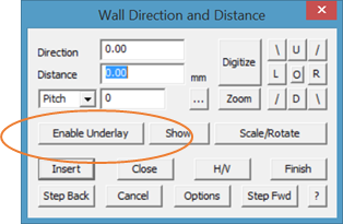
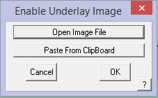
Selecting the [Enable Underlay] button brings up the options for the underlay image – from a file on disk or pasting it from the Windows Clipboard.
![]() Note: If you wish to use an image file (a PDF or JPG or similar), the image file must be in the …\User folder already if you are going to use the Open Image File option. So in fact the first step is to save the image file into the User folder before you start your job in Roof Wizard. File names must not have spaces in them – eg roof-picture.JPG, NOT roof picture.JPG
Note: If you wish to use an image file (a PDF or JPG or similar), the image file must be in the …\User folder already if you are going to use the Open Image File option. So in fact the first step is to save the image file into the User folder before you start your job in Roof Wizard. File names must not have spaces in them – eg roof-picture.JPG, NOT roof picture.JPG
Whether the image has been scanned or emailed as an attachement, you must save it to the User folder, whether your User folder is the default – C:\AppliCad\Roof Wiard\User or a network drive, say X:\\AppliCad_User, the files must be saved first. Navigating away from User to find the image files causes issue with the software later as the program remembers where you last looked for, in this case the images, and then can’t find default settings and material and labour files etc.
![]()
Any images that are intended for use by digitising must first be saved in the default …\User folder, except for those that you are pasting from the Windows ClipBoard.
Paste From Clipboard
Selecting the Paste From Clipboard allows the operator to place the clipboard image into the workspace on screen at an approximate scale directly from the Windows clipboard. The model construction plane is then aligned to the image and the model geometry is created in 3D. This is a very powerful tool, especially when used in conjunction with aerial image service providers such as Google™ (using the Google – Edit Copy Image function to clip the visible aerial image to the Windows clipboard) or PDF documents in Acrobat™ Reader (using the Acrobat Reader Edit > Take a Snapshot function).
The best way to achieve this is to review the aerial image, PDF document or scanned image at the largest possible scale to contain the entire roof plan on the largest possible screen, then capture it. You can use the Snapshot tool in Acrobat or the Windows accessory Snipping Tool.
Once placed into the workspace, the image is not to any set scale at this stage – scaling comes next.
Open Image File
We select the image we wish to use as the underlay for the digitising process. Select the option, Open Image File, and the user folder with all the saved images are displayed. They are sorted by bitmap type ie as BMP’s or TIF’s or JPEG’s. This is set by the drop down box at the bottom right of the dialog. Select the image type to use and then select your image, and then select Open.
The underlay image can be an aerial image or a scanned plan previously saved.
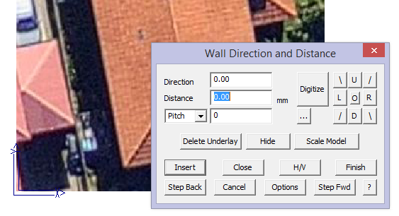
The image is placed on screen. It is really not at a known scale, so we must now scale it to a known size and the best size is full size or a scale of 1:1. The enable button changes to a delete button should you choose to remove the underlay image and use another or start again for any reason.
![]()
Please note that your use of Nearmap, Google, Pictometry and similar satellite or aerial imaging services is subject to their respective license agreements and AppliCad does not make any representation as to their accuracy or reliability. It is our view that these are merely tools that you, as roofers, can use selectively and to your customer’s advantage.
At this stage we don’t care whether it is an aerial image or a scanned plan. Once placed on screen, we must scale the image so we can digitise at full size.
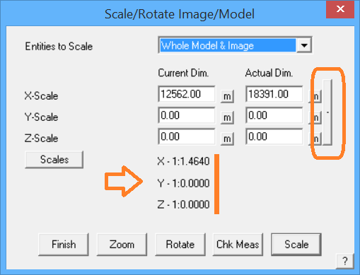
Scale/Rotate Image/Model
Selecting the [Scale/Rotate] button or the [Construct Roof > Underlay Image > Scale Image/Model] function on the Pulldown Menu allows the operator to scale the image before creating 3D model data – scaling the image and workspace to full size using various reference measurements, points or reference documents.
The image scale is then calibrated to the correct or full size. Once set, the plan and the workspace is at full size and all model geometry is created at full size. You must know what the actual size is and it is best to establish this across the widest part of the job to reduce error. In the aerial image service use their measure tools get the overall width or height of the job.
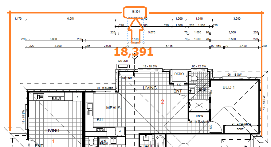
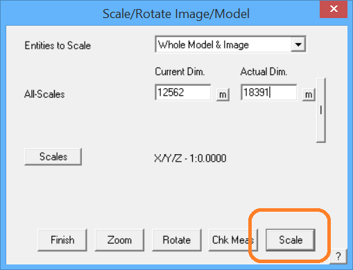
When selected, the following dialog is displayed where the dimension measured in the field or from the aerial imagery service is the Actual Dimension and the current model dimension is measured using the [m] button. Set the Actual Dimension to whatever is required – you would extract this from using the measure tools provided by the image service or read directly from the plan. Use the largest span of measurement as that will reduce the percentage error.
To ensure that you are getting the best possible possible accuracy for the scaling, scroll zoom close-in to the reference line for the overall dimension at each side of the job.
Typically, you would change all entities in the model so select the option – [Whole Model and Image].
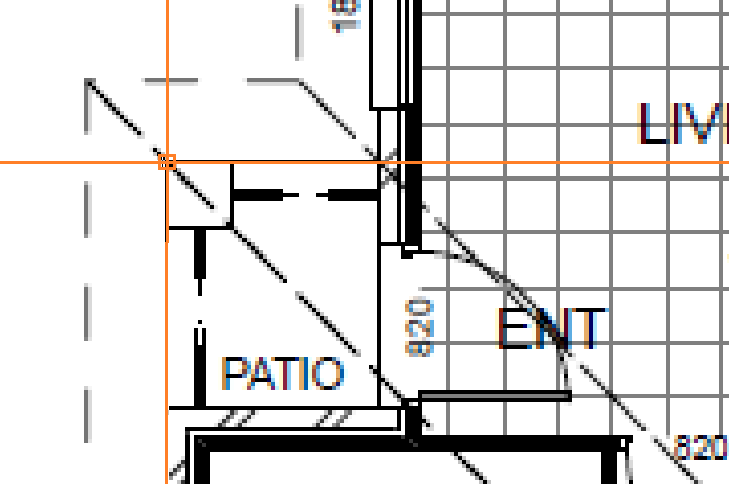
To determine the current dimension, that is the current size on the image in your workspace, select the measure button [m] and then using the middle mouse scroll wheel, zoom in to one corner and select the centre of the line, then scroll in to the opposite corner, for which you have a an overall dimension (18,391 in our example) and click that line. The image is rescaled within the workspace.
Check Measure
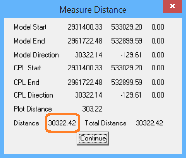
After you have scaled the model, it is good practice to use the Check Measure button [Chk Meas] to verify that you have scaled correctly. Follow the prompts and typically select one of the longest known measurements so that we reduce the percentage error. The resultant dialog shows the X,Y,Z of the start and end of the points being measured, and the distance is exactly the distance between the two points regardless of the axes.
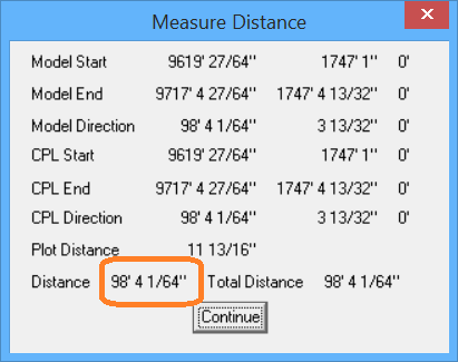
If we were checking the job and the known measurment was 30,325, the result below (30,322) would indicate that we have scaled quite well. This is in metric units of course. If you were working in Imperial, the measurements would be in Feet and Inches.
Select the bonding button [-] brings up the dialog as shown below and allows for scaling the whole job based on separate measurements in each axis that controls each scale factor in X, Y and Z. This function is hardly ever used in practice as it is generally assumed that the scale is the same in all axes.
‘Bonding’ button.
Using the middle mouse button scroll wheel and scroll out so that you can see the whole image. You will then decide where you wish to start digitising giving thought to what features will be added using Mod-Roof and those that you will pick up on the first pass around the perimeter outline.
Rotate Image
Most often, an image has been captured and it is not quite square to the X and Y axis of the work area. The Rotate Image button provides a way to rotate the image so that it is easier to digitise – without having to rotate the digitising axis also known as the CPL or Construction PLane.
Before [Rotate]
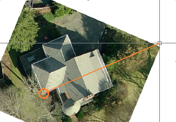
You are prompted to digitise the first point which will be the axis for the rotation, and then prompted for the second point which will be along the X axis and become parallel to the bottom edge of the work area and normal to the original CPL.
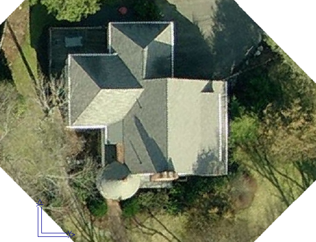
After [Rotate]
The result is an underlay image that is a lot easier to work with.
 Digitise Option
Now select the Digitise button and you will be prompted for the digitise options.
Remember, before you start digitising or tracing the perimeter of a PDF or an aerial image, you MUST scale the image using known reference lengths so that you are working at full size.
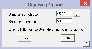
Set the Constrain the Angles to (typically 45°) and set the Constrain the Lengths to (typically 50mm or 2”) to ensure the roof model is square and as accurate as the image allows. For greater precision, simply reduce the constraint values, say 10mm or 1/2″.
Select [OK] and the cursor waits for you to select the origin corner of the building outline and you can start digitising the perimeter of the building outline using the left mouse button. You cannot use the middle mouse button to ‘snap’ to corners in the image as it is a pixellated image, it does not contain vectors (lines) or points to snap to. While digitising the outline, you can also type exact line lengths into the prompt area and that line will be drawn at the precise length. You can also cancel ‘digitising’ and use the track outline Direction and Distance fields to complete the outline.
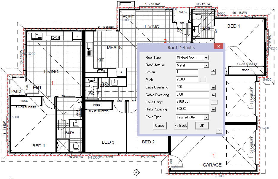
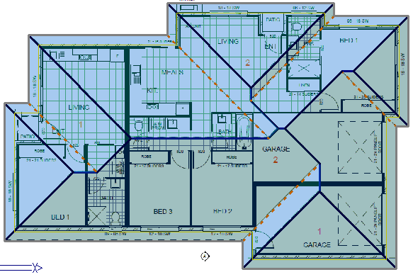
Work around the perimeter, scroll-zooming into each corner to locate it as accurately as you can, then at the penultimate corner, right click [Cancel], then [Close] and [Close Square]; then [Finish] and this brings up the Roof Defaults dialog. Fill out the variables as required, [OK] then [Continue] and the job is done.
It is also to a very high level of accuracy. This needs to be checked as usual and this is discribed in the opening home page – “The AppliCad Process”. You will also get a lot of value if you complete the first module of the AppliCad Academy where the process of modelling, checking etc is well described and you get to try it for yourself.
Close (Outline) Option
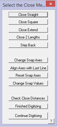
The [Close] methods are:
Close Straight – This simply joins the last point directly to the first point
Close Square – This creates another corner back to the original start point.
Close Extend – This extends the last direction to intersect the first wall.
Close 2 Lengths – Prompts the user to close to a pre-defined line length eg: by specifying two close lengths at the penultimate line on this outline; select [Close 2 Lengths] and the operator is prompted for the specified close lengths, then the approximate location of the intersection point and the last two lines are drawn at the specified lengths.
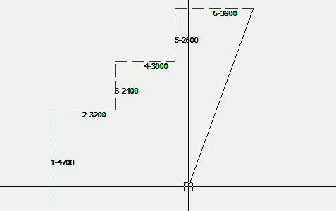
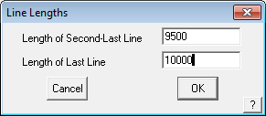
Resulting in something like this:
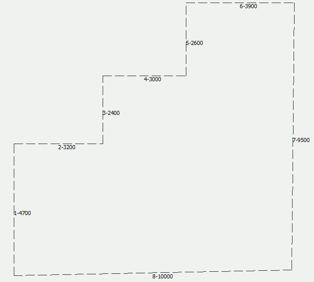
Which is clearly not square, but in accordance with the dimensions specified.
Step Back – Allows the operator to back track in the event that the line digitised is incorrect. The Ctrl Z keyboard short cut also takes you back one step.
Change Snap Axes – Allows the operator to change the direction of the Construction Plane (CPL) so as to continue digitising at a different orientation angle to the previously digitised lines. To access, when you need to change the CPL direction, right click the mouse and then select the option. The operator is prompted to select the origin of the new CPL, then the X axis of the CPL and then the Y axis of the CPL. Then select [Continue] Digitising. This may be repeated as many times as required until the job is completed. To finish, right click and select Close Straight or Close Square as required.
The CPL may be reset to normal model origin by selecting
Change Snap Axes – It is also useful to have the constrain angles set, typically to 45° so as to ensure that your outline is square at all corners.
Align Axes with Last Line – Rotates construction plane axes with last digitised line.
Reset Snap Axes – Resets the snap axes to original settings.
Check Close Distances – This command allows you to check the final two distances before you close the outline.
Finish Digitising – If there is a gap between the last and first points, then it does the same as the Close Straight method.
Continue Digitising – Lets the operator back into the digitise process.
You may also use the abbreviated method of typing C (for close-square) in the distance field, then enter. For a regular shaped structure, it is recommended that you input all but the last two lines, then use Close Square to close out the shape and let the software determine the last two lines for you. Notice that the length of the last two lines is displayed. Check that these match the plan and if they don’t, someone has made a mistake somewhere, either inputting the outline, measuring the roof or dimensioning the drawing. This is a quick and easy first check of your job.
Finish Option
Once the outline is fully defined and you are happy with the close distance, click the [Finish] button, or type F to finish the outline definition and go to the Roof Defaults dialog.
When you click Finish the wall lines are drawn and you are then prompted with the Roof Defaults dialog box. It is here that you define critical aspects of the roof geometry and it is important to note how these are linked with other Reporting stages.
Comments are closed.