Scale/Rotate Image
 Scale/Rotate – Image/Model
Selecting the [Scale/Rotate] button or the [Construct Roof > Underlay Image > Scale Image/Model] function on the Pulldown Menu allows the operator to scale the image before creating 3D model data – scaling the image and workspace to full size using various reference measurements, points or reference documents.
The image scale is then calibrated to the correct or full size. Once set, the plan and the workspace is at full size and all model geometry is created at full size. You must know what the actual size is and it is best to establish this across the widest part of the job to reduce error. In the aerial image service use their measure tools get the overall width or height of the job.
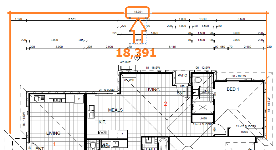
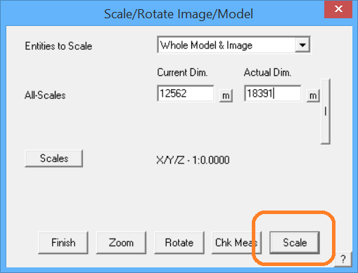
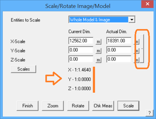
When selected, the following dialog is displayed where the dimension measured in the field or from the aerial imagery service is the Actual Dimension and the current model dimension is measured using the [m] button. Set the Actual Dimension to whatever is required – you would extract this from using the measure tools provided by the image service or read directly from the plan. Use the largest span of measurement as that will reduce the percentage error.
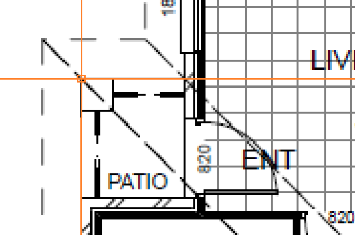
To ensure that you are getting the best possible possible accuracy for the scaling, scroll zoom close-in to the reference line for the overall dimension at each side of the job.
Typically, you would change all entities in the model so select the option – [Whole Model and Image].
To determine the current dimension, that is the current size on the image in your workspace, select the measure button [m] and then using the middle mouse scroll wheel, zoom in to one corner and select the centre of the line, then scroll in to the opposite corner, for which you have a an overall dimension (18,391 in our example) and click that line. The image is rescaled within the workspace.
Check Measure
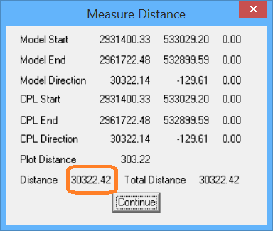
After you have scaled the model, it is good practice to use the Check Measure button [Chk Meas] to verify that you have scaled correctly. Follow the prompts and typically select one of the longest known measurements so that we reduce the percentage error. The resultant dialog shows the X,Y,Z of the start and end of the points being measured, and the distance is exactly the distance between the two points regardless of the axes.
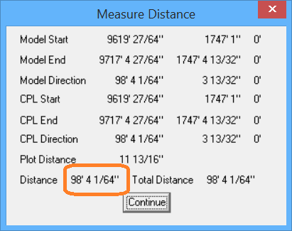
If we were checking the job and the known measurment was 30,325, the result below (30,322) would indicate that we have scaled quite well. This is in metric units of course. If you were working in Imperial, the measurements would be in Feet and Inches.
Select the bonding button [-] brings up the dialog as shown below and allows for scaling the whole job based on separate measurements in each axis that controls each scale factor in X, Y and Z. This function is hardly ever used in practice as it is generally assumed that the scale is the same in all axes.
‘Bonding’ button.
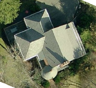
Using the middle mouse button scroll wheel and scroll out so that you can see the whole image. You will then decide where you wish to start digitising giving thought to what features will be added using Mod-Roof and those that you will pick up on the first pass around the perimeter outline.
Rotate Image
Most often, an image has been captured and it is not quite square to the X and Y axis of the work area. The Rotate Image button provides a way to rotate the image so that it is easier to digitise – without having to rotate the digitising axis also known as the CPL or Construction PLane.
Before [Rotate]
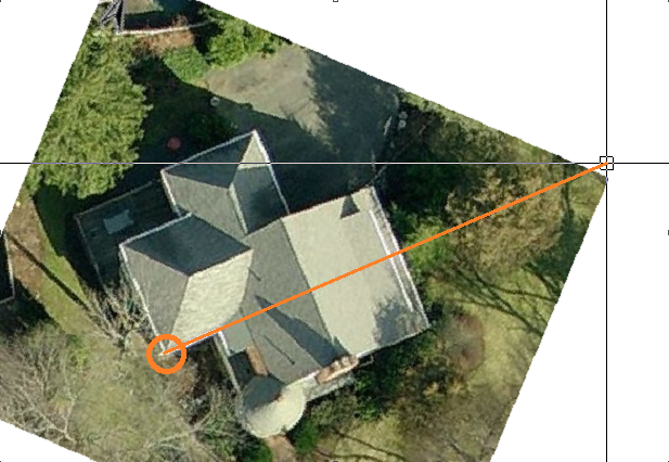
You are prompted to digitise the first point which will be the axis for the rotation, and then prompted for the second point which will be along the X axis and become parallel to the bottom edge of the work area and normal to the original CPL.
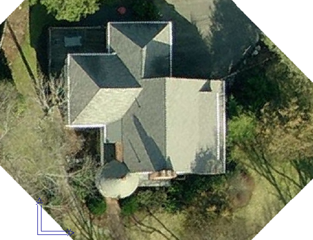
After [Rotate]
The result is an underlay image that is a lot easier to work with.
Comments are closed.