Measure Pitch from Oblique Aerial Image

Measure Pitch from Oblique Aerial Image
This function allows the operator to import an oblique aerial image and by placing the 3D cursor on a corner, typically an eave corner and aligning the X,Y, Z axes to the image, the pitch of the hip or gable end can be determined. The resultant pitch may be used to create a 2D model or a 3D model of your roof.
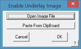
First, import the image. To do this select the Construct Roof > Track Outline function; and select the [Enable Underlay] image button (refer below for more detail) to place the image on screen from a file on disk or from the image in the Windows clipboard.
Then select the Construct Roof >Measure Pitch tool button.
The following dialog box is displayed and the 3D axis icon is placed at the model origin (X,Y,Z = 0).
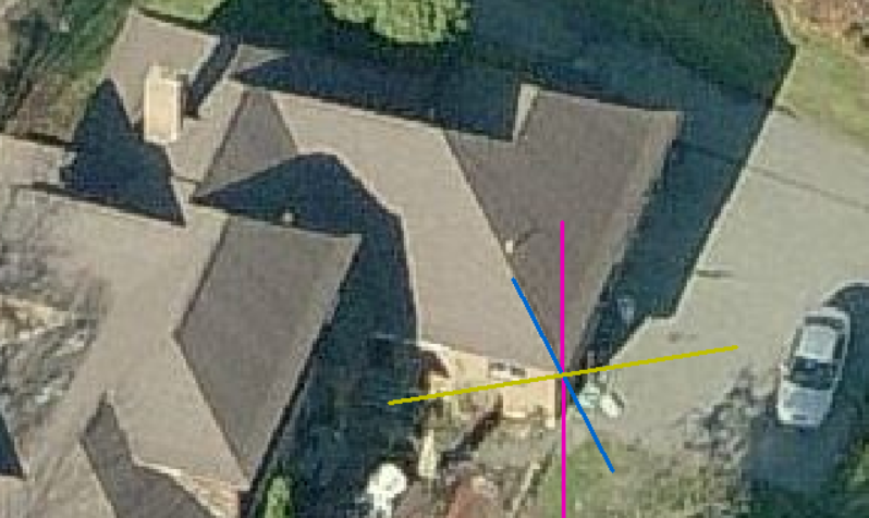
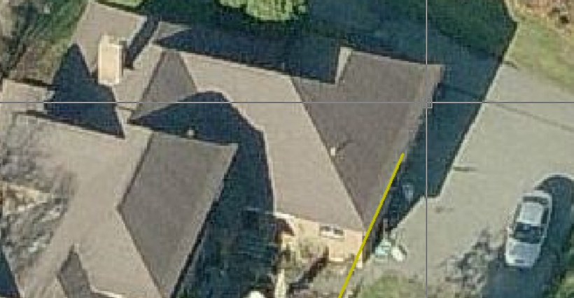
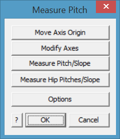 Select the button ‘Move Axis Origin’ to place the 3D axis icon on the corner of the eave. Then select ‘Modify Axes’ and follow the prompts to align the respective axes with the image. You can re-do this iteratively until you are happy with the placement. Right click [Cancel] to finish placement.
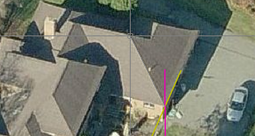
Next, select the measurement option that suits your job. The Measure Pitch/Slope options measure an angle in the selected plane. Typically the 3 axis indicator comes on screen at an apparent random location (where it was lasted used which may not match the current image). Use the [Move Axis Origin] button to position the axis indicator to the required corner of the building.
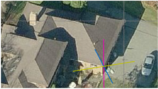
Next you will need to align each axis with an ‘edge’ in the image. Use the [Modify Axes] button, you will be prompted to locate each axis is turn, X, Y and Z to align the axis indicators with the view of the roof.
This function would typically be used to measure the pitch or slope of a gable roof as shown below.
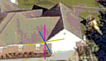
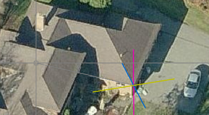
- Move Axis Origin (to align with a corner of the roof)
- Modify Axes (to align with image of the roof.
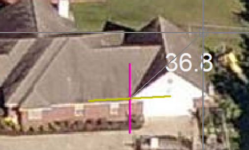
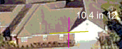
- Measure Pitch/Slope, select plane to measure pitch in (Typically XZ) and click a point in the line of the gable to measure the pitch (here the pitch is shown in degrees). You may also use slope.
If the pitch text is too small or difficult to read, use the [Options] button to change colour and size of text. You may also change the size and colour of the individual axes as well, so as to make the information easier to read.
Measure Pitch Options
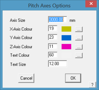 Axis Size sets the size of the lines on sceen representing the X,Y,Z axes.
Axis Colour sets the colour of each axis line from the CAD colour pallet.
Text Colour sets the colour of the text for the pitch dimension. Select a colour that contracts well with the underlay image.
Text Size sets the size of the text on screen, select a number that is large enough to read clearly.
Measure Hip Pitches/Slopes
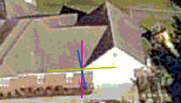
The Measure Hip Pitches/Slopes prompts for the other end of the hip from the 3D Axes origin, then the apex point of the hip. The hip end is drawn and the pitch of each plane displayed.
This function can be used to measure the pitch of hips and gables.
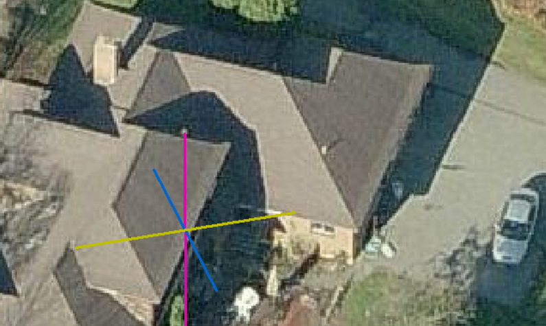
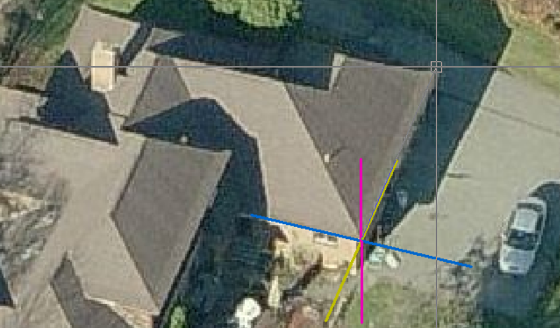
Placement of the 3D Axes origin point with [Move Axis Origin] button.
Left click on the corner of the hip to locate the position of the new axes origin. Align to image with [Modify Axes] button and you will be prompted for the new X axis, new Y axis and new Z axis (read the prompts).
New Y axis, and the new Z axis will usually be in the line of the current Z, straight up the screen. This may vary slightly depending on the image.
Now select Measure Pitches/Slope and read the prompts. You will be prompted for the Reference Axis (Base of Hip). Then the axis to measure pitch towards (usually Z axis).
Then indicate the other end of the hip end.
And next the approximate hip apex point.
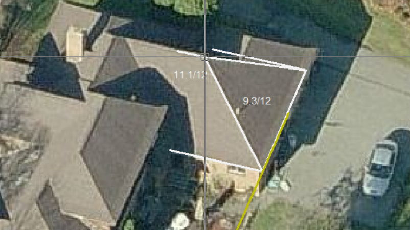
The hip is drawn and the pitches displayed. You may reselect the apex repeatedly to improve the accuracy.
The result will be in degrees, slope or percentage as set in the Set-Up > System Preferences.
Comments are closed.