System Preferences
Set-Up > System Preferences
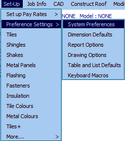
This command sets various operator preference settings such as the units, slope input and terminology of your installation. You should only have to set these options once. There are a lot of options here and setting them incorrectly may change the way the software works for you, so be sure you understand what you’re changing, and why, before you change it.
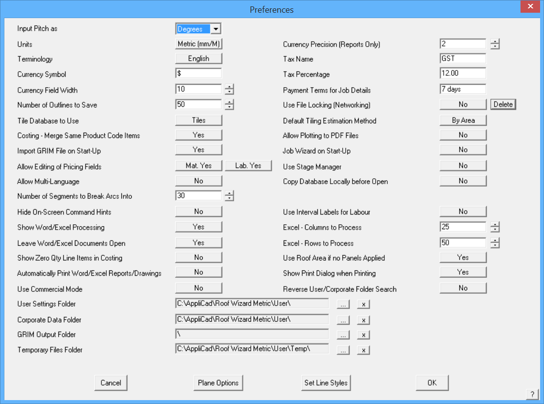
When you select System Preferences, the Preferences dialog box is displayed:
- Left column of Table
Input pitch as This is either Degrees (°) or Slope (in 12) or percentage (in100)
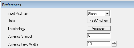
Units This is either Metric or Imperial
Terminology This is either English or American
The differences in terminology are
[Aust-English / American]
Sarking/Underlay
Battens/Purlins
Verandah/Porch
Cartage/Delivery
Downpipe/Downspout
Shell end/Hip starter
Apron/Skirt
Barge Rake/Verge, Rake
Colour/Color
Labour/Labor
Step/Roof-to-wall
It is fair to say that the terminology differences are notional only as regional differences also exist that make such a process flawed from the start.
Currency Symbol You can set this to any character or group of characters you want.
Currency Field Width This is the number of digits you want to be able to see in currency fields on the Reporting dialog boxes. If dealing in US or Australian dollars, the default is adequate. For Italian lire and Filipino peso, you may want to make it larger.
Number of Outlines to Save The number of job perimeter outlines saved to the file in date and time order, for later recovery under Const-Roof > Recover. Default is 20 but may be set to any number, say 100 or 150 for example.
Tiles Database to Use This is either Tiles or Tiles+. This selects the particular tile data file structure you wish to use for the Cover > Select-Tile command. They are not inter-changeable so be sure to read the respective descriptions in this manual to understand which one you should use.
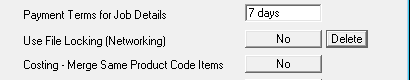
Costing – Merge Same Product Code Items Y/N – sets whether you want items with the same product codes to be merged into one line item in the material list under Reporting > Supply Only or Supply and Install. This function searches the job Reporting data for products that may be used for different applications (such as screws) but are actually the same product and product code, and adds them all together as one line item on the quotation.
Import GRIM File on Start-Up Y/N – Allows you to turn on or off the Import GRIM file process when you open the software.
Allow Editing of Pricing Files Y/N – Allows the administrator to set a password on editing material or labour pricing files to make them tamper tolerant. A blank file called sysprefspwd.dat is shipped with the software. This does not make the files tamper-proof, but it will certainly slow down unskilled or unauthorized users.
By default, the setting is Yes allowing anyone to edit any pricing file. If the option is set to No pricing options in all materials and/or labour under Set-Up are not accessible to the operator – they appear ‘greyed out’ on the dialog.
Allow Multi-Language Y/N – This option allows the software to operated in any language. All functions and dialogs now refer to an external file for the appropriate prompt to be displayed. By translating the files, there are 90+ files, to the required language the prompts will be displayed in this language. At time of printing German and Spanish are available and French is in the pipeline. The files must be saved in the folder ….\AppliCad\<program>\Language.
Number of Segments to Break Arcs into The software will only generate roofing and cladding to lines, but if an arc is found, that arc may be divided into line segments so that the geometry for the roof or wall will still be constructed correctly. Effectively the number of segments sets the resolution of the arc.
Hide On-Screen Command Hints Y/N – Allow the display or hiding of on-screen tooltip hints (on by default).
Show Word/Excel Processing Shows each stage of the output being processed as the report is generated. Only applies when the report is being generated from a Word Template or Excel spreadsheet.
Excel – Columns to Process Limits to range of cells in Excel to process. Useful if the total matrix of cells is large.
Excel – Rows to Process Limits to range of cells in Excel to process. Useful if the total matrix of cells is large.
Leave Word/Excel Documents Open This leaves Word or Excel open with the generated report displayed. This is useful to make further edits or check the result before printing.
Show Zero Qty Line Items in Costing As it suggests, enables the option to display the zero quantity items in the costing report screen (Reporting > Supply Only or Reporting > Supply and Install). You would leave on so that you can modify the quantity to add an item. This may be used as a prompt for occasional use items such as fuel surcharges etc. Create a bunch of Extra Items with zero quantities and they become your check list.
Automatically Print Word/Excel Reports/Drawings Y/N – When set to Yes, the report is printed to the default Windows printer, as soon as Word or Excel completes creating the report from your template.
Use Commercial Mode Y/N This option enables the use of Substrates, Systems and Assembly Groups for specific large scale operators interfacing with very large material databases and assemblies. Not for general use. Leave set to No unless specifically requested by the AppliCad Support department to change.
File Directories These are the directory(s) where the system will look for your data files. These are the data files containing material definitions and labour rate details (.dat and .bin and some .dab files). It does not include the CAD (.dab) files you create for your jobs. If there is no directory path, then the system first looks in your User directory. If the file is not found there, it looks in the Programs directory.
You select a new folder or directory by clicking the ‘…’ button. Clicking the ‘x’ button will reset the folder or directory to nothing. If you wish to use a folder or directory on a file server so data files are accessible over a network, you will first need to map the network drive using Windows Explorer.
Setting User and Corporate data Folders
From AppliCad Version5.8 onwards a new folder structure has been implemented to provide for more comprehensive data and job file management, especially at larger sites with many operators. If you are a single operator, keep it simple. The default settings for folder locations are as displayed – local drive, C or D:\AppliCad\Roof Wizard\User.
Refer to Section 6 for a summary of file types and where they must be located for correct operation of the software. Set the path to folders according to your system set-up. If you are unsure, please refer to your System Administrator or IT expert or call the AppliCad Support Team.
- Right column of table…
Currency Precision (Reports Only) This allows you to set the number of decimal places you want your currency to appear on your reports only.
Tax Name This is the name of the taxation system in use in your country. (eg: GST, VAT, Sales tax). You will see this value displayed on the various Reporting dialogs and the reports where tax is required.
Tax Percentage This is the tax percentage you want to set.
Payment Terms for Job Details This is the payment term you want to appear on your reports.
Use File Locking (Networking) In larger firms where the estimating office has multiple operators doing estimates, file locking restricts the operator from opening a job already being worked on by one of their colleagues. This prevents inadvertently over-writing some else’s work or data-files. If the software has been closed in error and lock files have not been properly cleaned up, it may be necessary to delete them. This may be done with the button – Delete to delete existing lock Files – these are files in the …\User folder with a *.LOC extension.
Default Tiling Estimation Method Presets the estimating method quantifying tiles, shingles, shakes and slate – the options are by Area or by Course. Area calculates quantity based on pieces or bundles per square and Coursing actually lays the pieces course by course on the roof model and then counts the pieces. (Waste, if defined, is applied later, during the cost reporting operation of Supply Only or Supply and Install).
Allow Plotting to PDF files Y/N – Allows the operator to print directly to PDF files. Requires a third party PDF generator such as Adobe Acrobat™ or PDF995™ to be installed (not supplied by AppliCad Software).
Job Wizard on Start-Up Y/N – If set to Yes, the Job Wizard guides the operator through the steps of creating and estimating a job. This is especially helpful to new operators and is usually turned off once the process is learned and understood.
Use Stage Manager Y/N – Turns on the stage manager function if you require the ability to break a quotation down into Stages – refer to Stage Manager elsewhere in this manual for more details of Stage Manager.
Copy Database Locally before Open Y/N – Added option to “Copy DABS Locally” which will result in database files being copied to the local machine before being read by the software. This switch can improve database read and write speeds across slow WAN and LAN networks.
Use Interval Labels for Labour Y/N – allows the output of labels set up under Set-Up > Metal/Tile Pay Rates Variable > Intervals to be displayed in the Labour dialog of the Costing > Supply&Install dialog and also to be output in the GRIM file exported – (Set-Up > Pay Rates > Metal/Tile Labour > Intervals)
Use Costing Plus Y/N – this function allows the software to use the Tiles+ tile structure and the Costing+ pricing structure to make comparisons with cost and sell price to determine profit margin.
Excel – Columns to Process Limits to range of cells in Excel to process. Useful if the total matrix of cells is large.
Excel – Rows to Process Limits to range of cells in Excel to process. Useful if the total matrix of cells is large.
Output of Material Cutting List Y/N – This allows you to change the output of your material cutting list, from Feet & Inches to Inches only.
Note that this is only applicable for those working in Imperial measurements. It is not displayed when in Metric units.

Use Roof Area if no Panels Applied Y/N – If no panels have been appied to the roof model, the roof area will be used as the roof area quantity for material cost purposes (based on the cost per square (foot or metre) of the selected material item.
Show Print Dialog when Printing Y/N – If you have a single printer then typically you would set this to No and it will go directly to that printer. If you have a range of printing options as you might have on a network, then set to Yes and select the required printer to send the print job to.
Reverse User/Corporate Folder Search Y/N – Allow the software to search the “Corporate Folder” prior to the “User Folder” when looking for databases, models, CSV files etc. This function will allow the user to copy a number of “Corporate Default Settings” to the Corporate folder and by setting this switch to Yes, will ensure these options are found by the software before being located in the User folder. Thus, Corporate Standards will be able to be maintained more easily while still allowing other settings to be set by the user.
Plane , Roof and Wall Line Options Buttons

Displays a dialog box to select what plane or line options you wish to set up.
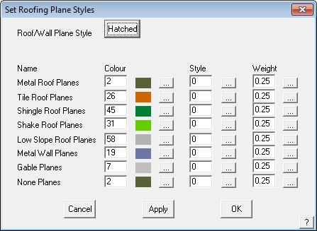
Roof/Wall Plane Options
Selecting Plane Options brings up the following dialog box where the operator an set whether roof and wall planes are displayed as a filled area or as cross-hatched lines.
If Filled Planes is selected, the Filled Plane Intensity needs to be set, making the filled planes lighter or darker.
Any category of material can be set to any colour number. Any colour number can be any colour, set using the function CAD > Defaults > Colour Table. Remember that these colour numbers may be used for many entity types, so if you change colour 10 for this purpose, it might not be what you need where colour 10 is used elsewhere, for a line type for example.
Once set, select Apply and the new settings are applied to your job. These settings are saved with the job when you select File > Save.
If Roof/Wall Plane Style is set to Hatched, then you get extra options to set for the line style used for the hatch pattern – Style, whether it is a dashed, dotted or solid line; and Weight, the ‘thickness of the line when displayed on screen and plotted on the page.
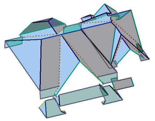
Roof model with Filled Planes
Once set, select Apply and the new settings are applied to your job and are then used on all subsequent jobs.
These settings are saved when you select Apply, [OK] and then [OK] again in the Preference Settings dialog. They are also saved with the job when you select File > Save.
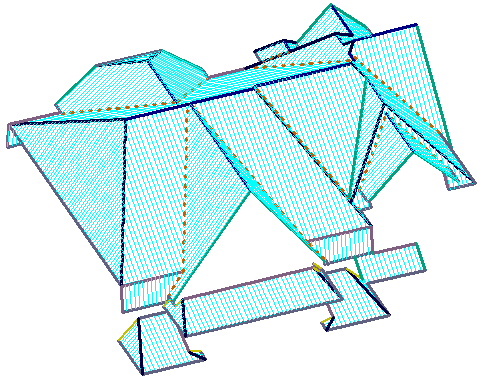
Roof model with Hatched Planes
Roof/Wall Line Options
This command lets you set the colour, style and weight (line thickness) of the different line types in a roof and wall model.
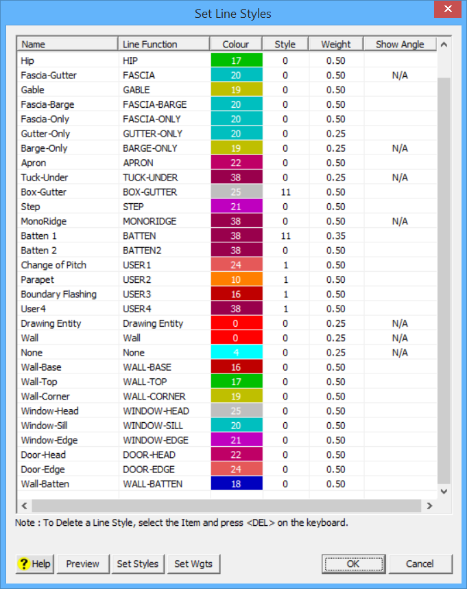
When Roof Line Options is selected the roof line styles are displayed and may be changed to suit the personal preferences of the operator. The Line Function is the name Roof Wizard uses for a line, the Name is the term operator wants that line to be called. Once changed, that name is used through out the program, where ever that line Funciton is used. Obviously it is preferable that each line function has a unique name. Set line colours, styles a line weight to suit the needs of your office. If you have a dark background in the prgram’s workspace, then dark lines will be hard to see. Similarly, white lines are impossible to see on a white background. When selecting line colours, also consider the output reports. Most of us print onto white paper, so select line colours that will stand out!
Extra User-Defined Line Styles The operator may define 4 additional line styles or categories for use on the roof model – USER1 – 4. Once the names are defined, they become visible throughout the Cover > Flashing type options and also for Tools > Change Line Type options.
When you click Apply, the changes are made to the lines in the current model and the dialog box remains displayed. When you click [OK], the settings are saved and are used for lines inserted from now on.
Regardless of what name is used, the line style function is as described in the second column. This is important to keep in mind when setting up flashing and trim options under the Flashing command.

When you click the colour setting button, the Defaults Colour dialog box is displayed.
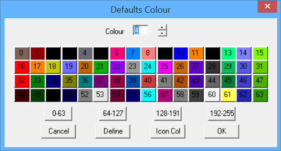
Here you click the colour you want, and then click [OK]. You will then see the colour index transferred to the Set-Line-Styles dialog. This changes the colour number. A colour number may be any colour. The colour map for each colour number is defined using the Defaults Colour Table accessed by selecting the [Define] button.
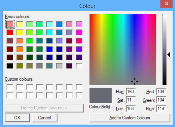
Select from the basic colours, or define a custom colour by using the Hue, Saturation, Luminosity scales or the Red, Green, Blue scales. Once selected, select [OK] and that will be the line colour used. Make allowance for the screen workspace background colour settings you use as well as how the selected colour will appear on a printed report and indeed, whether you are printing in colour or monochrome.
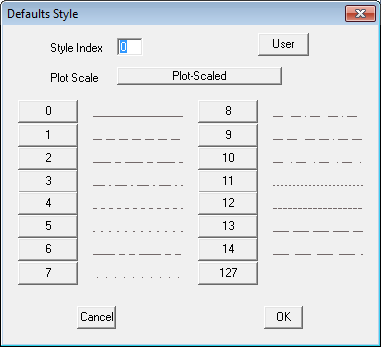
Line Style and Line Weight
Selecting the line style and line weight is similar in operation.
Below is the Defaults Style dialog box. Selecting a style number changes the line style for that line category. For example, valley lines are often selected to be a dashed line to highlight them against hip lines.
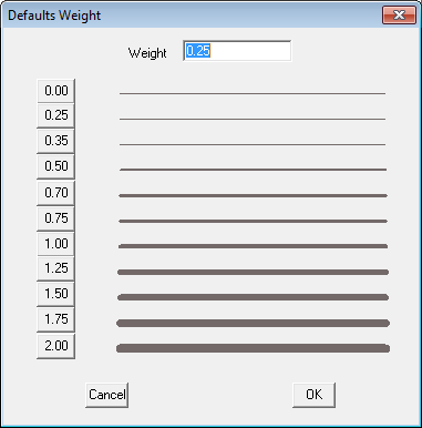
Below is the Defaults Weight dialog box.
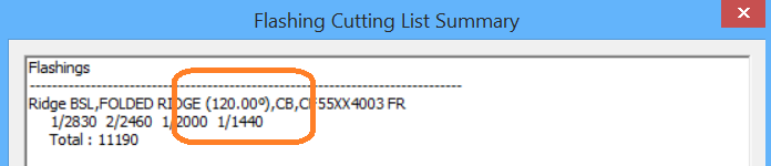
The Show Angle option displays the angle of bend for the trim, which is the angle between adjacent roof planes. It becomes part of the information in the flashing cutting list. When selected, the X appears in the cell.
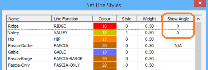
To set, simply double click the cell on the dialog and then the angle will be displayed as part of the flashing report as shown below in the cutting list summary.
Dimension Default Settings
[Pulldown Menu Only]
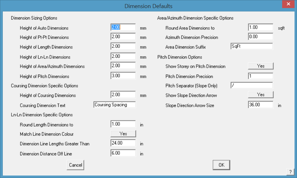
After selecting Defaults, the Dimension defaults dialog is displayed.
[Set-Up > Preference Settings > Dimensions Defaults]
![]()
Note: Typically, the font used to annotate roof planes and drawings is the font defined under CAD > Defaults > Text Defaults. As these may change from user to user, it is suggested that a text file called Fontfile.dat be created and saved in the User folder, thus ‘locking-in’ the required font style for each user. The font used on the roof plan for annotation such as area, azimuth etc will then be determined by the font defined in the Fontfile.dat. True type fonts will be listed by their name only (such Arial or Calibri) and the CAD fonts by the name and the extension (such as HELV.FON for Helvetica font or ISO.FON for CAD ISO font). If no font file exists (it must be created by the user) then the CAD text default settings will be used.
Dimension Sizing Options
These options allow you to alter the size of dimensions for the four different methods. You will see the effect on screen and on the printed drawings.
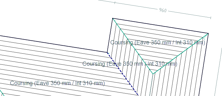
Coursing Dimension Specific Options
Set the height of the course dimension text and also the information to be displayed on the roof plan. For example – Coursing (Eave ###E mm / Int ###I mm) would insert Coursing (Eave 350mm / Int 310mm) on the drawing as shown below.
Ln-Ln Dimension Specific Options
Round Length Dimensions to .. sets the rounding up of the dimension number drawn on the roof drawing – in the example ±10mm.
Match Line Dimension Colour changes the dimension colour to be the same as that set for the line making it easier to associate a dimension with the matching line. If set to no, the default settings for dimension are used.
Dimension line Lengths Greater Than allows the operator to set how short the shortest lines to be dimensioned will be. Anything shorter than the specified length will not be dimensioned. This takes the clutter out of the drawing by not dimensioning lines that may not be important.
Dimension Distance Off Line sets the distance the dimension is to offset from the associated line – roof plan on the left is set to 0; roof plan on the right is set to 100mm.
![]()
Note: Be careful switching between metric and imperial units as this can have a detrimental effect on settings such as arrow size – 100mm in metric becomes a 100” in imperial.
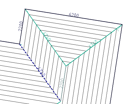
Without offest from the referenced line.
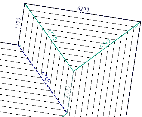
With offset from line set to required distance.
Azimuth/Area Dimension Specific Options
Round Area Dimensions to sets the rounding up of the area dimension number drawn on the roof drawing – in the example ±1sqm.
Azimuth Dimension Precision sets how many places after the decimal point.
Area Dimension Suffix adds a suffix to the area dimension such as SqFt or SqM.
Pitch Dimension Specific Options
Show Storey on Pitch Dimension adds the roof storey to the pitch dimension drawn on the roof plan. Used in conjunction with the precision, in this case one decimal place.
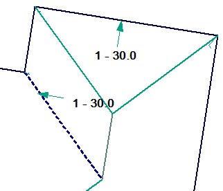
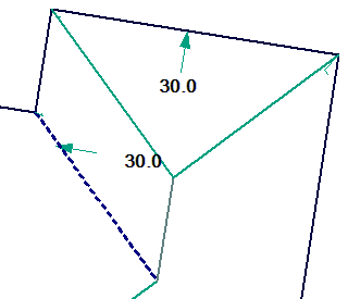
Pitch Dimension Precision sets how many places after the decimal point. Our example displays one decimal place.
Pitch Searator (Slope Only) sets the separator character btween the numbers indicating the slope of the roof. Typically a colon as shown, but may be a slash.
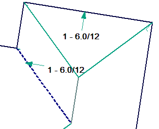
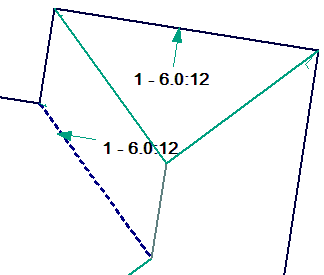
Show Slope Arrow Direction – Y/N Slope direction arrow may or may not be displayed.
Slope Direction Arrow Size sets the size of the arrow. Since we model the roof geometry at full size, the arrow would need to be about 1000mm as shown above (or the equivalent in feet and inches).
![]()
Note: Be careful switching between metric and imperial units as this can have a detrimental effect on settings such as arrow size – 1000mm arrow in metric becomes a 1000” arrow in imperial.
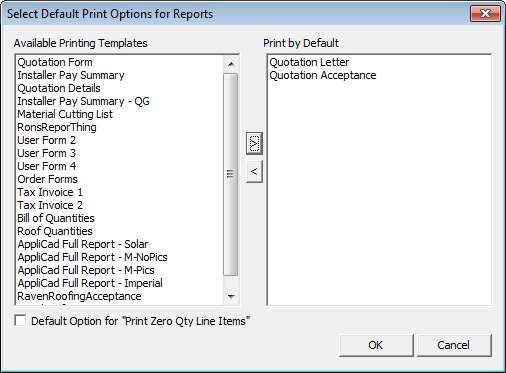
Set Report Options
This option provides the opportunity to pre-set the required reports that you would normally print, thus saving the time to select them for each job at the print stage.
Set Drawing Options
This option provides the opportunity to pre-set the required drawings that you would normally print, thus saving the time to select them for each job at the print stage.
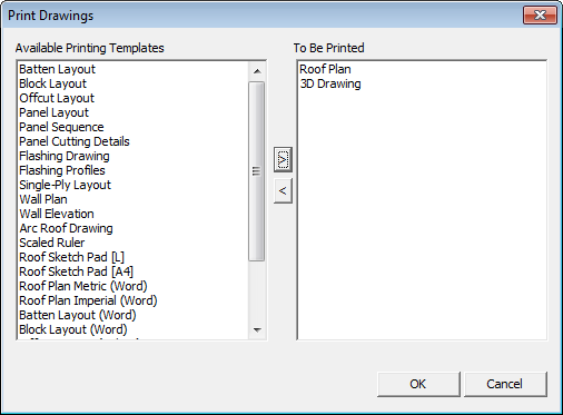
Table and List Defaults
Opens the dialog box where the text height for each standard report table or details text is set. The units are millimetres (do not use feet and inches).
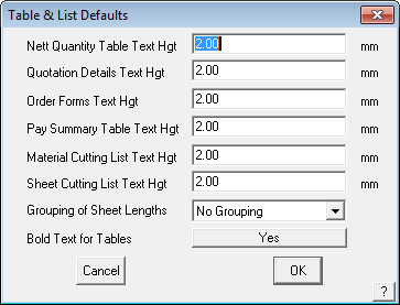
The option “Grouping of Sheet Lengths” refers to the creation of the sheet/panel cutting list and the options are No Grouping, Group by Length Alone or Group by Plane and Length.
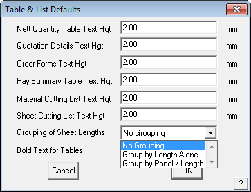
The Group by Length has the cutting list sorted by length. The Group by Plane and Length sorts them by plane then length, thus giving a list that relates to each roof plane.
The Bold Text for tables is self explanatory.
Keyboard Macros
This menu option starts the keyboard macro recording function, allowing you to ceate new keyboard commands for any key on the keyboard.
Upon selecting the ALT key or CTRL key from the keyboard, its currently assigned command statement is displayed in a dialog box. The selected key may then be re-assigned with a different command statement.
Main menu commands can be assigned to the selected key by beginning the command statement with !mainand then specifying the command and its modifier levels.
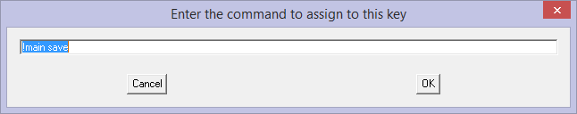
For example, the following command statement will enable File > Save the current database: !main save
The Inline Menu commands can be assigned to the selected key by beginning the command statement with !menu and then specifying (if required) the command and its modifier levels. For example, the following command statement will enable the Inline Window command, set all options to Yes and then await window definition: !menu window out cross [OK]
Comments are closed.