Flashings
 Flashings
This command allows you to set the flashing you want for each of ridge, valley, fascia, gutter, barge, apron, box gutter and step flashing. These become the global settings for each of the flashing line category types. You can select predefined flashing or define custom flashings.
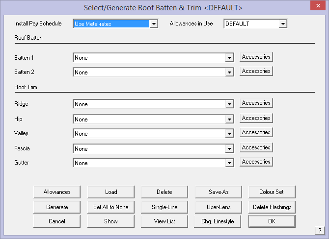
After you select Flashing, the roof flashing and trim material dialog box is displayed. If no flashing lines have been defined (typically when no job is present) then you get a virtually blank dialog.
As the model is created and as line types are added to the model during construction of the roof model, the list is populated with line categories (as shown below). Each line category has a drop down list of all predefined flashing that match that category.
![]()
Note: The software is aware that some roof systems, typically residential have relatively simple systems with fixed options for panels and flashing or trim with modest accessory lists. For commercial / industrial metal roof systems they can and usually do become quite complex, especially in the area of edge treatments (assemblies), substrates and predefined accessory systems. Please refer to Section 2 for detailed instructions for creating these definitions.
Precise definition of all material parts is ESSENTIAL for the application and automatic parts list generation to work correctly.
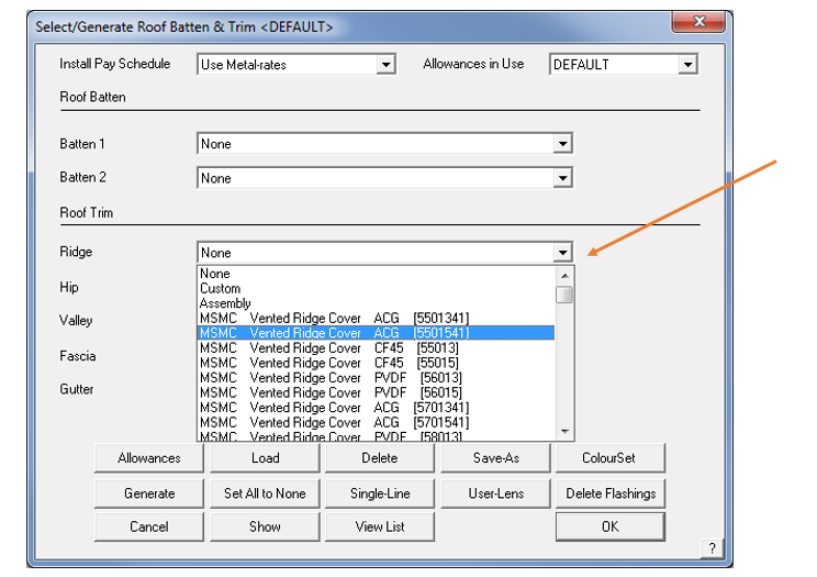
As the examples on the previous page shows, all your pre-defined flashing options are displayed that match the line category – None (no trim is applied to the line); Custom (custom fabricated trim parts) and Assembly (for aggregated or groups of flashing materials that make up an edge treatment such as a box gutter or parapet cap); or a bought in regular flashing item usually fabricated in a roll-former.
All these materials must first be defined using Set-Up > Flashing. Refer to this section of the Reference Manual and the Setup Guide for more details about defining and using your flashing materials.
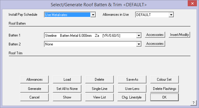
At the top of the box, is the option to select the required Install Pay Schedule for Supply and Install jobs. This rate is defined under Set Up > Metal Pay Rates. You may define several Metal-Rates but remember the overhead of keeping them up to date and current. Only define as many rates as you need for the way your crews work. Refer to that section of the manual for how to define your pay rates.
Adjacent to Pay Schedule, is the option for Allowances in Use. This displays the allowance file in use. The drop down box allows you to select from all the allowance files you have defined. You set up the allowances using the dialog that opens by selecting the Allowances button at the bottom left of the page. You may have many different allowances for various roof systems. See below for details.
The flashing material colour defaults to the colour of the roof material. If you need a different colour, remember to change it.
Roof Batten/Purlin
The operator has the option of selecting the main roof batten plus a secondary or intermediate batten where the building code requires such a device – usually as a fall barrier for installers.
Selecting the Batten or Batten2 buttons brings up the list of batten/purlin materials available for that line style. In this example we have quite a few batten material options.
![]()
The roof batten button Batten has an Insert/Modify option. Selecting this button opens up the dialog box shown below and allows for comprehensive set up of your roof battens/purlins. Battens/purlins may be inserted and quantified on metal or tile roof categories. The tile roof category is primarily for those roofers installing metal tiles such as Metro or Gerard. Clay and concrete tilers typically build the cost of their timber battens into an all inclusive price.
Once selected, the following dialog box is displayed showing the options for inserting the battens/purlins.
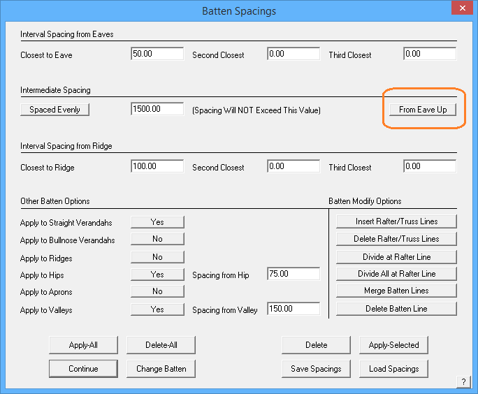
The operator can define the batten spacing and the program provides for the spacing to use near the top and bottom and left and right of the roof plane to suit the requirements of certain building codes, especially in cyclonic or hurricane prone areas.
The intermediate batten spacing may also be set. The options for the intermediate spacing, that is the batten spacing after the pre-set batten spacing, may be a fixed spacing of the specified amount or spaced evenly along the length of the roof plane up to the maximum spacing. Note ability to space battens/purlins from top (ridge line) down, rather than the bottom (eave) up.
Other Batten Options
Apply to straight verandahs This is a toggle to determine if you want battens drawn on straight verandahs in this job.
Apply to straight verandahs This is a toggle to determine if you want battens drawn on bullnose verandahs in this job.
Apply to Ridges Applies battens along the ridge line on each roof plane with a ridge line at the spacing from the ridge that you specify.
Apply to Hips Applies battens along the hip line on each roof plane with a hip line at the spacing from the hip that you specify.
Apply to Aprons Applies batten to apron lines.
Apply to Valleys Applies batten to valley lines.
Many batten/purlin configurations require the battens/purlins to be split at a roof frame member – a rafter or a truss. This may be the case for a typical portal frame commercial structure. If the battens/purlins need to be split, use the Divide at Rafter Line option then the operator needs to indicate at which frame member the batten/purlins will be divided.
Individual battens/purlins can be divided or all the battens/purlins on the roof plane using the Divide All at Rafter Line.
If a line is not on the drawing where you need a batten/purlin divided, then you have two options to insert a line to use as a reference line to divide the batten/purlin. Insert Rafter/Truss Line option prompts for a line parallel to the required rafter line. An adjacent eave line will usually do it. Then you are prompted for the spacing or offset from the reference line to the location of the required rafter line.
The Delete All Rafter/Truss Lines option deletes these lines once the operator is complete and they are not necessarily required to be displayed on the drawing.
If a batten/purlin is incorrectly divided, then use the Merge Batten Line button. The Delete Batten Line completely removes the Batten/Purlin from the model.
Apply All Applies battens/purlins using the spacing definitions set.
Delete All Deletes all batten/purlins from the model.
Delete Deletes the battens as selected.
Apply Selected Applies battens to a wall using the current settings. Use this to modify batten spacing on a wall by wall basis.
[Continue] Takes the operator back to the Flashing dialog to continue setting up roof trim.
Change Batten Changes to a different batten material.
Save Spacings Saves the current settings. Use this to set up different spacing settings for various roof systems.
Load Spacings Read into the current job, spacing settings from a predefined set.
The battens are drawn on the model according to your specification. Select [Continue] and you will be returned to the Select/Generate Roof Batten/Trim dialog box.
![]()
Note: This process may be used to design and estimate a retro-fit batten system such as RoofHugger™. This is described in detail in the Appendix.
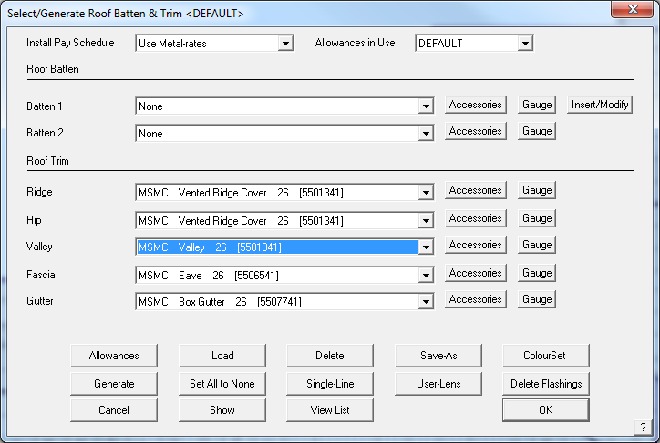
Selecting a Flashing
The select flashing (trim) option displays a dialog as shown below. Only line-type options that exist in the model are displayed. That is, if a box gutter line type does not exist in the model, then that row of option is not displayed. This keeps the selection process simple to manage. If you subsequently add a line type, then that row will be displayed and you must go back and assign a trim profile to it.
To select a new flashing for a particular line type, click the relevant flashing cell (Ridge, Valley, Fascia etc) and the available definitions for that category are displayed.
Here you can:
Select None and have no flashing on this line type.
Select Custom, and have a custom profile on this line type. A Custom flashing is typically a flashing fabricated in a press break to particular specifications.
Select Assembly so that an assembly of flashings, defined previously as either a regular flashing or a custom flashing, will be attached to this line type. If the assembly has a graphic figure associated with it, then you are prompted to insert it on the drawing. The assembly is still selected even if you cancel the insertion of the figure. The figure is ignored when you print the automatic reports and drawings. However, you can compose your own plot using the Plot command. (See Set-Up > Flashing-Details to create an assembly.)
Select a regular flashing material. These regular flashing profiles are usually fabricated in a roll-former and cut to length. These materials are defined by the Set-Up > Flashing command.
Refer to the relevant section in this manual – Set-Up > Flashing, Set-Up > Flashing-Assemblies and Set-Up > Custom Profile – for more information on how these are all defined.
If the flashing you selected defined as Colour, Color, Coloured, Colored or painted, then you are prompted to select a colour from the Metal Colour list too. Metal colours are defined under Set-Up > Metal Colours.
Selecting a custom flashing
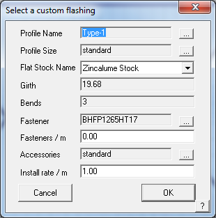
You select a custom flashing by selecting Custom from the flashing list. After you select Custom, the Define a custom flashing dialog box is displayed.
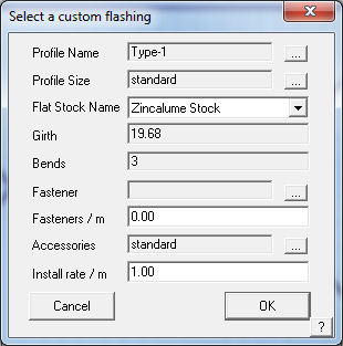
Name This is the name of the Flat Stock Sheet table you defined under Set-Up > Flat Sheet. This table defines the fabrication cost given a matrix of girths and bends. It also defines the stock sheet size and material and finish.
Girth This is a drop down box of girths defined in the relevant table
Bends This is a drop down box of bends defined in the relevant table
Fastener This is the fastener you want to use for this flashing. To select a flashing, click the button on the right hand side.
Fasteners/m This is the number of fasteners you want per unit length
Profile name This is the name of the actual profile to be used. This list is derived from profiles you created from Set-Up > Custom-Profile. If you select a profile you will be able to verify the profile graphically as well as produce custom flashing reports.
Accessories This displays the list of accessories for the profile. If you had filled out the accessories using the Set-Up > Custom-Profile > Accessories command, you can then see them here. You can also change them if you wish. If you do not change the list, the word “standard” is displayed. If you have changed the list, the words “non-standard” are displayed.
Install rate/m This is the where you set the labour rate for the custom flashing
When you select the profile selection box, the following dialog box is displayed.
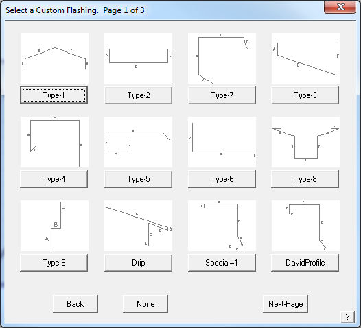
This dialog displays for you a selection of those profiles you have created. To select the one you want, click on the button beneath the graphic.
When you select a profile, the Define Profile Dimensions dialog is displayed.
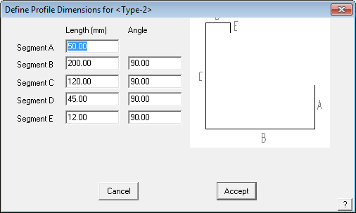
Here you either accept the default values (the values used when you drew the profile) or change the dimensions and angles to suit this particular job. You can also change them if you wish. If you do not change the list, the word “standard” is displayed. If you have changed the list, the words “non-standard” are displayed in the Profile size field.
When you click Accept, the definition is saved and the Custom Profile dialog is redisplayed.
Now you see:
the profile name you selected
the profile size. The size is either “Standard” if you did not change the default dimensions,
name of the flat stock sheet from which the custom profile is fabricated
the girth and bends of the profile
the fastener you want to use
and the installation rate for the labour.
When you click [OK], you are returned to the Roof Flashing Material dialog and that material is listed against the line type.
Flashing Allowances
To set the flashing allowances, click the Allowances button.
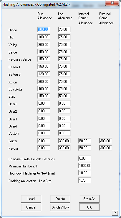
Here you can set the standard allowances you want to add to each flashing type and sheet. After you select this command, the Flashing Allowances dialog box is displayed.
Metric or imperial units must be used in accordance with whatever you have set as your system units of measure.
Metric is displayed here.
Run Allowance This is the amount added to each run regardless of the length of the run. You can treat this value as an end allowance.
Lap Allowance This is the amount you want to add to take piece overlap into account
Internal Corner allowance This is the amount you want to add to a gutter or fascia run if there is an internal corner at an end.
External Corner allowance This is the amount you want to add to a gutter or fascia run if there is an external corner at an end.
Combine Similar Length Flashings After you generate a flashing list, lengths which are less than this amount apart, are assumed to be the same length and are merged together. The shorter lengths are merged into the longer lengths. This helps the installers by not having too many different lengths in the pack and overcoming the portential of cutting the longer back only to leave a shorter one that is now not suited to the task.
Minimum Run Length This is the minimum run length which will be treated as an independent run. Runs less than this length will be added to an attached run.
Round-off Flashings to Next This can be defined as any number, it will then round up to that number.
Flashing Annotation – Text Size This sets the text size on the flashing report that is printed. It is millimeters. If you work in Feet/Inches, it still uses millimeters. 2.5mm is pretty close to 1/8th”.
Load
This button allows the operator to load a previously saved flashing allowance file.
Delete
This button deletes an allowance file.
Save-As
This button allows the operator to save an allowance file that suits a particular roofing system. You may have as many different allowance files as you need.
Single-Allow
Clicking this button lets you set a user defined allowance to a particular run. For example, you may want to add extra allowances for valleys around dormers.
After you click Single-Allow, you enter the allowance you want to add, then select the line you want to add the allowance to. When the flashings for this run are quantified, the run length will then become the actual length of the line plus the allowance.
When you click [Cancel] the flashing dialog box is displayed and changes you made to the allowances are discarded.
When you click [OK], the flashing dialog box is displayed and changes you made to the allowances are retained. If you have created an allowance file, you will see [OK]/Update which gives you the option to change the currently displayed allowance file.
![]()
Note: Be aware that the DEFAULT allowance settings are not saved as an external file but within the Roof Wizard. If you change the settigs and select [OK], they become your new default settings. You can change the settings and select Save-As and define a new name such as ‘Corrugated762’ and these will be saved to a file called Corrugated762.AL2. They will then appear in the list of saved trim system allowance settings for flashings and trim, all with the *.AL2 file extension.
Generate
This command generates a flashing cutting list for this job depending on the estimation you have set for each flashing type. If you have selected an estimation method which deals with each run individually, the cutting list for that run is automatically annotated on the drawing. If you have selected a batten, but not inserted them, then you are prompted to do so.
When you click this command, the flashing list is displayed on the Flashing cutting list summary dialog box. All flashing and trim items are listed and below that are all thr flashing and trim accessory items.
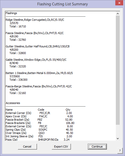
Here you see the cutting list for each flashing type, as well as the number of flat sheets for the custom flashing. The Accessories button brings up the list of all accessory items required to complete this installation.
If you want to export this flashing list to a comma separated value file (.csv file), a text file that can be read by a text editor for import into another system, click ExportCSV. To see the accessories quantified for all the flashings in the list including stop ends, gutter clips and rafter brackets etc, click the “Accessories” button.
![]()
Remember: To accurately report the flashings in the Reporting summary, you must ‘Generate’ the flashings first. If you change any flashing type, you must re-Generate the flashing list.
Click [Continue] to return to the flashing dialog box.
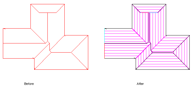
The following diagram shows the cutting list displayed on the roof model.
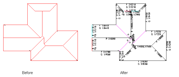
Delete
This will delete the flashing cutting list you have generated. The cutting list annotations in the model are also deleted.
View-List
This command displays the previous flashing list you generated.
Single-Line
This command lets you assign one or more extra or different flashings to a line you select. When you click this button, you are prompted to select a line. This is the line to which you will be adding or changing the list of flashings. After selecting the line, the following dialog box is displayed.
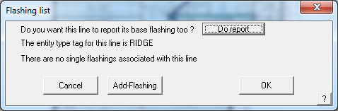
This dialog box shows you the line type for the line (in this case it is a FASCIA). You can also ask the system to report the base flashing for the line as well, or not, by clicking the ‘Do report’ button which toggles from ‘Do report’ to ‘Do not report’.
If there are no single flashings attached to the line, you are informed that ‘There are no single flashings associated with this line’.
To attach a flashing to the line, click Add-Flashing. Single Line flashings may also be inserted along arcs. The list of flashings is then displayed, from which you select one. After you have selected a few flashings, the dialog box would look like the following.
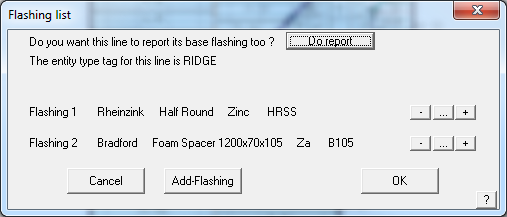
In this example, 3 flashings have been selected. For painted flashings, you are also prompted to select a colour for the flashing. To the right of each flashing are three buttons allowing you to delete the flashing, change the flashing or add a new flashing to the one you have selected. These are the buttons labelled [-], […] and [+].
When you select [OK], you get the opportunity to continue selecting other lines that might have the same unique treatment on them. Right mouse click to ‘cancel’ and quit changing the lines. Quite complex trim systems can be made using this technique – for example vented ridges. All the required accessory items as have been defined for each trim/flashing item are also quanitifed automatically, based on the definitions.
User-Lens
This command allows you to add user defined flashing items to lines in the model. First, the Select a flashing dialog is displayed. This list will display only those flashings defined as User defined. Then you select the line or lines you want to apply this flashing to.
Chg. Linestyle
Allows the operator to change the line from say, ‘Gutter’ to ‘Fascia and Gutter’, without having to exit the Flashing dialog.
Save-As
This command sets the currently selected flashing types to be saved as a “system” for future use. A naming convention that identifies the “system” such as ‘SSR Trim’ or ‘CorruTrim’ would work. This is then available for immediate selection when required.
Show
This command will annotate the supplier, description and code alongside each flashing run in the model for you to verify the flashings. A repaint will remove the annotations.
Colour Set
To quickly set the colour for each of the Coloured flashings, click Set Colour. Then select the colour you want.
Setting the pay schedule
For Roof Wizard and Roof Wizard the pay schedule is set under Cover > Select-Metal and defined under Set Up > Metal-Pay. For Roof Wizard and Roof Maestro, the metal pay schedule is selected on this dialog box by selecting an option from the pay schedule dialog box. If there are no schedules to choose from, then you must define some using Set Up > Metal-pay.
Close the dialog box by clicking [OK].
Comments are closed.