Custom Profiles
 Custom-Profiles
The following commands let you create a profile to use as the defining shape of a custom profile flashing, and to assign accessories to that profile.
Once created, Custom-Profiles may be varied at selection time as they are applied to your job. The angle of bend can be varied and the length of each segment can be varied.
With this in mind, one can easily imagine that just a dozen generic profiles could be used to define all your needs. They can also be aggregated under the Assembly function where complex trim systems can be made using multiple trim profiles.
Create
This command creates a profile shape for later use as a custom profile. The process to create a custom profile is:
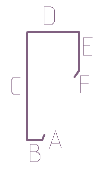
Draw the required profile exactly to size (using Construct Roof > 2D Design > Track-Lines or CAD > Line > Insert) and ignore bend radii, they wil lbe accounted as part of the manufacuring tolerance.
For example:
![]()
Note: The outline of the profile will look a whole lot better on the report that is generated if the line is heavier so that it stands out on the workshop detail drawing report. Use a line weight of say, 0.75. Feel free to use any other line weight or line style that works for you.
You are then ready to use the lines as the defining shape for the custom flashing.
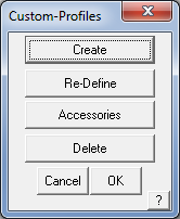
Select Set-Up > More… > Custom-Profiles and the following prompts are displayed. Select Create, and you will be prompted for a profile name to use to define the shape for later recall.
You are then prompted to select the lines and where to insert the segment identifier; select the line and then select the spot where you wish the identifier to appear for each line. The size of the text defaults to 2mm. This may be modified by changing the tag text defaults.
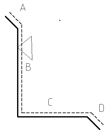
By convention we place the text on the outside, or painted side of the flashing profile. Other conventions might be used to indicate painted side – such as the dashed line or the arrow. These are simply drawn onto the figure, but NOT selected as part of the trim profile during the creation of the part.
Once all the lines are identified, right click and you will be prompted for an installation rate (per metre or per foot).
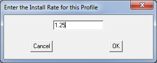
Select [OK] and this command saves the annotated drawing with lengths and angles of each segment as defaults when you select that custom profile for later use.
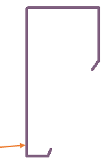
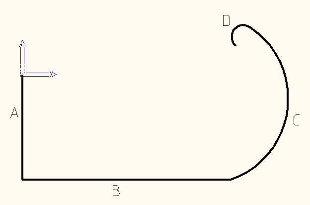
The Custom Profile definition may include an arc as well as lines as shown below. The assumption of course is that the press-break or folding machine controller can handle arcs. In such a case the line preceding the arc is used to determine the angle of bend.
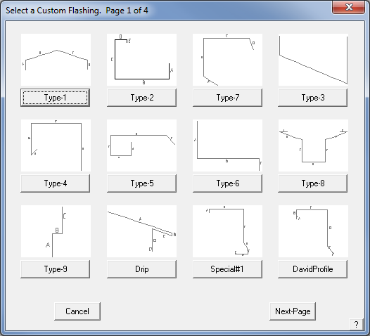
Once defined, you use this new profile by selecting the keyword ‘Custom’ from the flashing list when you want to select a flashing. Refer to the Cover > Flashing command below for details.
![]()
IMPORTANT NOTE: Because the use of the Custom Flashing function allows for modification of the basic parameters of a profile (such as angle of bend or length of an individual segment) as required for various jobs, then you don’t need to define 100’s of profiles. It is anticipated that all the variations for your trim profiles could be easily accommodated in say, 15 to 20 basic profile descriptions. You then adjust the length of individual segments or angle of bend to suit the immediate needs of that job, without defining a whole new profile. These adjustments are applied to the current job and do not affect the original definitions in the custom flashing data file.
Re-Define
The Re-Define option allows you to change the bend order or installation cost details of an existing custom profile definition. If you are modifying and existing profile, Select St-Up > More…> Custom Profile then select Re-Define from the dialog box. The following box is displayed showing all the currently defined profiles. Select the profile you wish to change.
The following prompt is displayed asking if you really wish to proceed to modify the selected profile. Select Yes to proceed to modify the profile. The previous profile is displayed and the operator is prompted to select the line to apply the segment identifier letter to as described above.
If the profile shape needs to be redefined, it is easier to simply delete the old one and define a new one as described above.
Accessories
This command lets you assign the required accessories to a custom profile you have prepared. To assign accessories, you are prompted to select a custom profile from the dialog box and the one you just defined will be displayed.
After selecting the particular profile (by clicking the button below the picture of the profile), the Define Accessories dialog box is displayed.
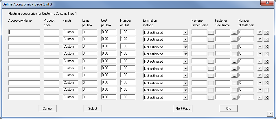
Here you define the list of accessories you want to use with the profile. After entering a name and a product code, you need to enter the finish of the accessory. Refer to the description of this process above. By default, the accessory will adopt the finish of the stock sheet to which the profile will be selected. If you do not want that to happen, then you can enter the finish you want (eg Painted, zincalume, galv, etc).
Then you enter how many items there are in a box, the cost per box and the estimation “number”. To get more details about the “number” and the estimation method, please refer to the Set-Up > Flashing command above.
The [M] button toggles between [M] and [L] signifying whether the accessory is reported as a labour item or a material item when you cost the job using these profiles.
The [X] buttons at the end of the accessory description allow you to delete a previously defined accessory item.
Delete
The delete button allows you to delete a previously defined profile.
Comments are closed.