Flashing Assemblies
 Flashing Assemblies
This command allows you to set up roof flashing assembly details. These definitions comprise one or more flashings as well as a flashing detail graphic. Each flashing item used in an assembly must exist already as a standard profile or custom flashing profile material as described in the Flashing page.
Name of flashing assembly This is the name you define for this flashing detail. You will use this name later when selecting flashing or edge assembly details.
Database name of graphic detail This is the name of the database (*.dab file) containing the subfigure of the graphic detail (the next field). When you click this field, you can select the database you want. The default database name is EdgeAssembly.dab.
Figure name of graphic detail This is the name of the subfigure to be inserted when you select this flashing assembly or detail. When you click this field, the list of subfigures in the given database name are listed. From this list, you select the one you want.
Add-Flashing This allows you to add a flashing to the list of flashings which define this edge assembly.
Add-Accessory This allows you to add ab accessory item to the list.
Add-fastener This allows you to add a fastener to the list.
Modify/New This allows you to select an existing flashing assembly definition or add a new flashing assembly definition.
When you click [OK], the details are stored in the binary data file called – EdgeAss.csv.
Material data files such as this are best edited from within AppliCad software via the appropriate dialog box, however as they are in a comma separated text file format (CSV) they may also be edited in a spreadsheet program.
Assembly Groups
This function has been developed expecially for commercial metal roofing enterprises dealing with many 100’s or even 1000’s of variables with flashing and trim combinations. The purpose of an Assembly Group is to link a group of Flashing Assemblies to a specific group of roofing or wall cladding panels.
Assembly Manager operates in 2 different modes ‘Non-Commercial’ or regular mode or ‘Commercial’ mode with full Assembly Manager capability. These modes can be determined by selecting “Commercial Mode” under Set-Up > Preferences > System Preferences. It is advised that you do not select ‘Commercial’ mode if it is not required, as it does create extra work to maintain.
Non-Commercial Mode
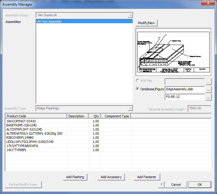
In Non-Commercial Mode, the software operates as described above – Flashing Assemblies. Assemblies are stored in the EdgeAss.CSV file and displayed on the dialog box as follows:

Assembly Groupings, Types, Nominal Lengths, PDF File and Rules are all disabled in non-commercial mode. Modify/New allows you to modify an existing assembly name or add a new assembly.
Selecting [OK] saves away the current assemblies list to the file EdgeAss.CSV.
Commercial Mode
In Commercial mode, the assemblies are assumed to be complex and that there will be many of them (typically > 500) and so the assemblies are stored in a binary format (non man-readable) for faster software access. Assemblies are grouped according to Assembly groups that must first be set up in order to define the binary files that assemblies can then be stored within.
Assembly Groups
To create an Assembly group, the user will go to the Set-Up -> Assembly-Groups menu and simply create a group by naming it in this dialog:
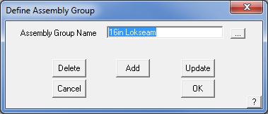
The creation of an Assembly Group then allows the user to link a group of Flashing Assemblies to a specific group of roofing or wall cladding panels when they are defined. This link may be made after panels have been defined and ‘Commercial’ mode enabled.
Assigning a Panel to an Assembly Group
In Commercial mode, roof and wall panels can be assigned to a specific Assembly Group. This is done by accessing the Set-Up -> Metal-Panels function and selecting the Assembly Group from the drop-down option in the dialog:
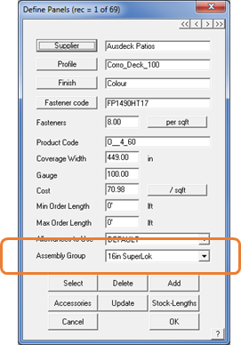
If you have no intention of using Assembly Groups, then you do not have to select an Assembly Group when you define your new panel profile.
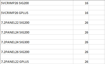
Alternately, the linkages between panels and Assembly Groups are stored outside the software in a file called SgroupLink.CSV. This file can be modified manually in a text editor or Excel, although care must be taken to use the correct product code from the panel and the index of the Assembly Group:
Assembly Manager
In commercial mode, the Assembly Manager takes on extra functionality. This functionality provides for Assembly Groups.
Assembly Group – Allows the user to select which Assembly Group we are looking at. Greatly reduces the complexity in numbers of Assemblies being modified. Modify/New allows the Assembly Groups to be modified, created or deleted.
PDF File – Instead of just a database/figure being specifiable to indicate how an assembly is to be installed, a PDF file can be specified for commercial customers. At a later stage in the process, the PDF files can be grouped together and printed en-masse to produce a document set for installation of this specific project.
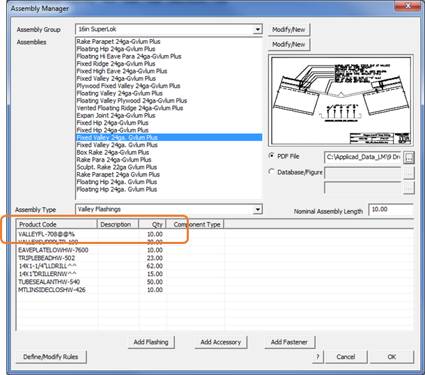
Assembly Type – Allows an Assembly to have a type assigned to it, so that it can only be assigned to certain line types within the software – for example, in the dialog above, the Assembly has been defined as a Valley type and as such, can only be applied to Valley lines on your model.
Nominal Assembly Length – Allows a notional length to be specified for the selected assembly for costing purposes, thereby making the specification of quantities for parts and pieces of the assembly much less complex. For instance, in many markets such as North America most assemblies are specified in 10’ length multiples.
Assembly Manager Rules
Rules can be created for Assemblies that allow the software to automatically swap parts in or out of an assembly, based on various decisions made during a project setup.
For example, let’s assume we have 5 different valley flashings, with the following product codes:
VALLEY22G – 22 Gauge Valley Flashing - Galvanized
VALLEY24G – 24 Gauge Valley Flashing - Galvanized
VALLEY22C – 22 Gauge Valley Flashing - Painted
VALLEY24C – 24 Gauge Valley Flashing - Painted
VALLEY24X – 24 Gauge Valley Flashing - Hi-Protective Coating
If we were to define an Assembly that used this flashing category, we would need to take into account all of the different valley flashing options of gauge and finish and create many separate flashing definitions to cover these. Instead, Roof Wizard allows us to define a flashing with variable values that might include universal variables that look like this – VALLEY@@% – where the @@ symbols are used to replace the product gauge at selection time, and the % symbol to be replaced by the material selected. This allows the product code for the correct flashing to be substantially simplified and automatically built up by the software.
Note that this process presumes that your product codes are organized in an orderly way. If the product codes in your organization are not organized in a sequential way as shown in our example, you will struggle to use the rules to reduce the number of assemblies you need to define. The product code structure you implement for trim and flashing items is key to the success of the Assembly Manager in managing huge component product lists.
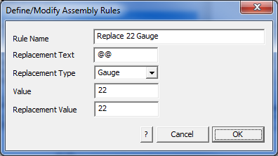
Example Rules can then be set up similar to the following examples:
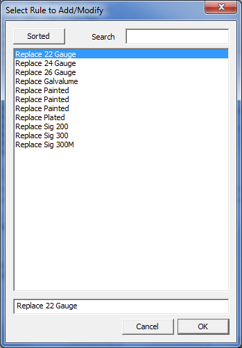
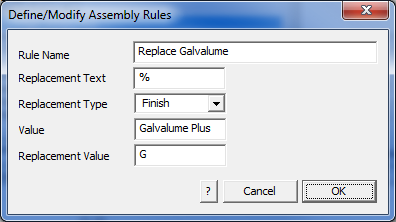
The first rule below tells the software to replace any instance of @@ in the Assembly Product Codes with the value of 22, when the gauge is 22. The second rule tells the software to replace any instance of % in the Assembly Product Codes with G if the finish of the product is set to “Galvalume Plus” as shown in the examples below:
There is no practical limit to the number of rules that you can set. This makes for a very powerful tool to manage even the most complex roof and wall trim systems automatically.
![]()
NOTE: When setting up, start with simple examples and test that you have done it correctly before you launch yourself at the entire product list in your company.
Comments are closed.