Zones
Zones
The Cover > Zones function allows the operator to define areas of a roof where materials are quantified differently according to their respective locations on the roof. Typically this function is used for calculating materials for retrofit roofing where wind loading must be accounted for. In areas prone to high wind and storms, the roof area is typically divided into ‘Zones’ where extra fasteners and battens/purlins are required to increase the wind load rating.
Field Zone Edge Zone Corner Zone
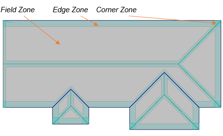
The process is straight forward and what follows describes the use of Zones for a typical retrofit situation.
Model the Roof and Insert Zones
First thing to do is model your roof geometry then select the menu option Cover > Zones. The following dialog box is displayed where you set up the zone offsets or spacing from the specified line types. When inserting the Zones, they must be inserted in the order indicated – that is, Corner Zones, then Field Zones and finally Edge Zones. Note that the lines must have an assignment of type. A ‘None’ line type will not create a zone offset.
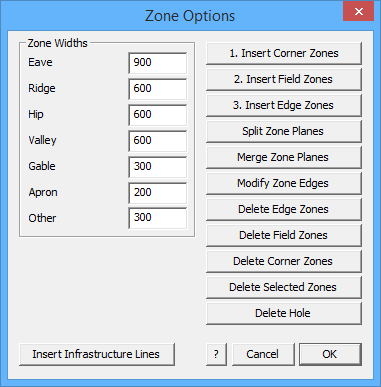
![]()
Note: Any plane in a model may be changed to a Zone plane and used as described above. This is done under Tools > Change > Plane Material.
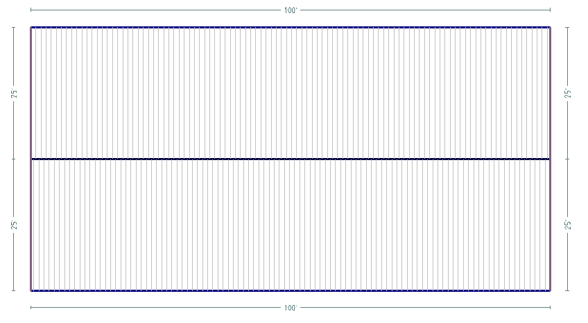
First model the roof geometry.
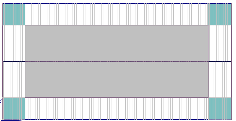
Select Insert Corner Zone(s) – all zones must be inserted in the order as numbered on the dialog box.
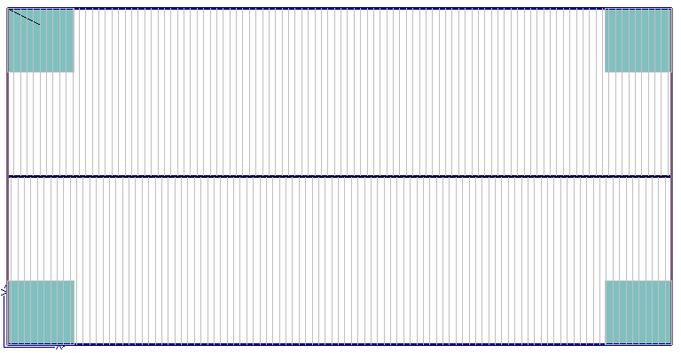
Select Insert Field Zone(s) – the operator is prompted to insert zones on Selected Planes or All Planes.
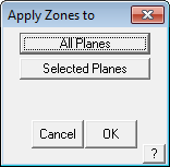
Field zones are inserted automatically based on Zone Option settings.
Select Insert Edge Zones and All Planes and the edge zones are inserted.
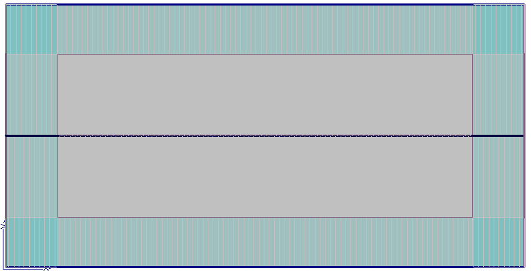
Once all the Zones are inserted (and the required materials defined), the lines representing the required roof systems materials must be inserted on the model.
Zones impact the use of materials and in particular, the use of additional fasteners based on the Zone definition. This requires the respective materials to be defined under Set Up > Flashings/Panels etc.
Typical Use of Zones
Insert the existing Purlins using Cover > Flashings > Purlin 1 (select and use Insert-Modify to insert them – refer to that section of the manual below [Cover > Flashing] for a detailed description of inserting Purlins). These become the primary structure for aligning and installing the new retrofit materials further constrained by the inserted zones.
Check Set-Up of Materials
You must also define line styles that suit the system you’re installing. In this example we will be using the Roof-Hugger purlin system to describe the retrofit system.
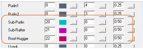
Go to Set-Up > Preference Settings > Systems Preferences and set User line types such as Sub-Rafter, Sub-Purlin, Roof-Hugger etc. While in Tools, it would be useful to check the line colour and style of the newly defined User defined line types – Set-Up > Preference Settings > Line Styles – so that they are clearly indentified on the model.
Extra User Defined Line Types

Change Line Styles
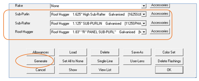
Next go to Set-Up > Flashings and set up your roof huggers, sub-rafters and sub-purlins.
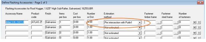
Use the estimation options under Accessories to determine number of fasteners based on Intersection with Purlins, Sub-Purlins, Sub-Rafters etc. making sure that the correct accessory items such as clips and screws are defined as required, taking careful note of how these are associated with the flashing item.
For more detail please refer to Section 3 of the manual that deals with defining Flashing/Trim.
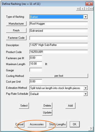
Selecting the correct Estimation Method is critical for accurate take-off of additional fixing items. These set up details only need to be done once.
They are now ready for use and re-use on all upcoming jobs.
Select Cover > Flashings. All line types currently on the model are listed. The next step is to insert the existing purlin system. Select a purlin to be inserted for Purlin 1 and select the Insert/Modify button [1 below]:

Set the required intervals for the existing purlins and select Apply All. The existing purlins are inserted. Check that the Intermediate Spacing is correctly set for your situation – typically use Fixed Spacing.
The existing purlins inserted and displayed.
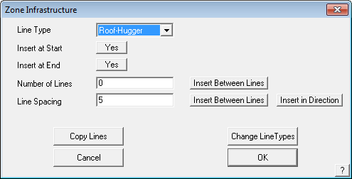
Zoom in to one corner to make it easier to find control lines. The next step is to insert the various infrastructure for the retrofit roof – the sub-rafters, sub-purlins and new roof purlins. Select the Zone Infrastructure button [2] Insert/Modify. The following dialog is displayed which helps automate and control the insertion of retrofit structural items.
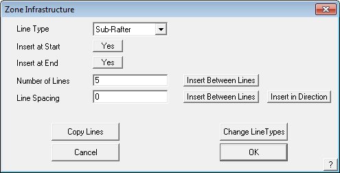
Line Type The type of line to be inserted
Line at Start Installs a line at the starting edge of the zone.
Line at End Installs a line at the end of the zone.
Then two methods of installing the lines; either –
Number of Lines The number of lines to be installed across a zone area spaced evenly between the start line and the end line.
Insert Between Lines The operator is prompted to select the Start Line and the End Line.
Line Spacing Uses a fixed spacing as defined here to insert the lines.
Insert Between Lines The operator is prompted to select the Start Line and the End Line.
or
Insert in Direction The operator indicates the direction the lines are to be inserted at the specified spacing.
Copy Lines Allows the operator to select all lines in say, a corner zone, to another corner, thus speeding up the process of doing multiple corners that have identical structures.
Change Line Types Allows the operator to change one line or multiple lines from one type to another – eg Sub-Rafters to Sub-Purlins.
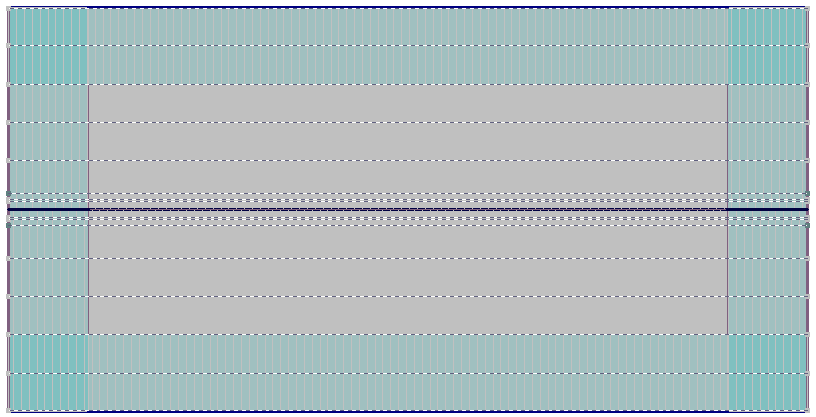
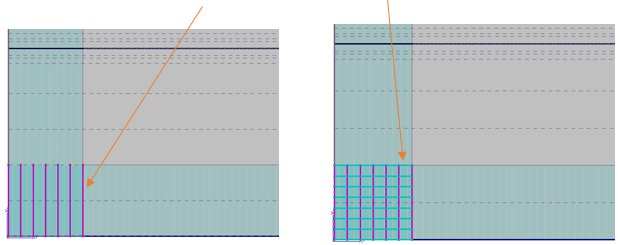
In this example if we were to install Sub-Rafters first, then select that Line Type in the Zone Infrastructure dialog, then the number of lines and select the Insert Between Lines button. Select the left hand edge of the Corner Zone, then the right hand edge of the corner zone, the Sub-Rafters are inserted.
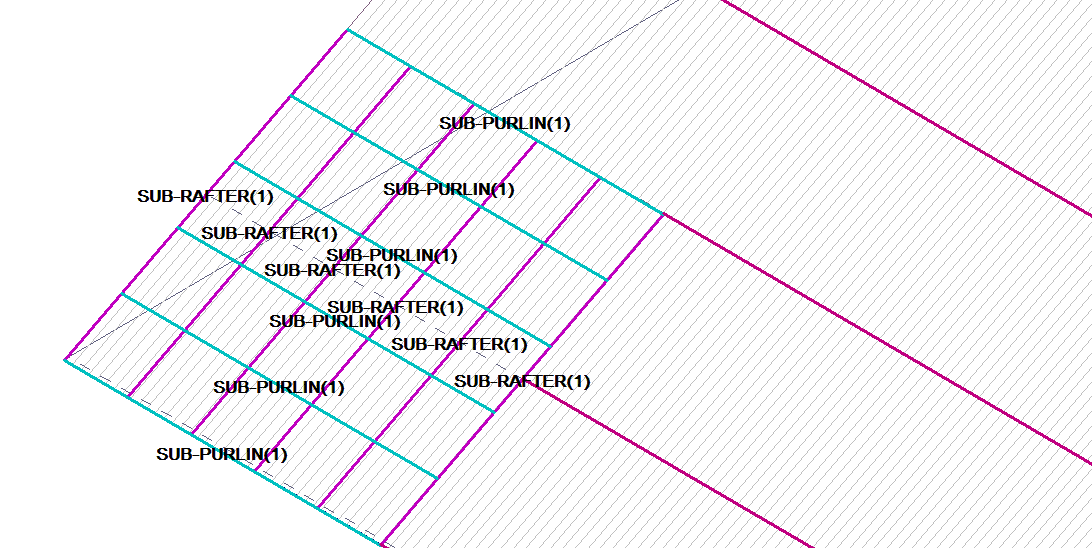
Existing purlins Sub-Rafters (Short vertical lines) Sub-Purlins (Short horizontal lines)
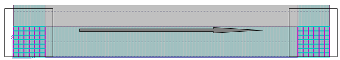
With the Sub-Rafters and Sub-Purlins inserted in the Corner Zone, the operator can now copy the whole set of lines to the other corners. Select the button, Copy Lines. Select the lines to copy and then following the prompts for start point and end point, snap the required points with the middle mouse button.
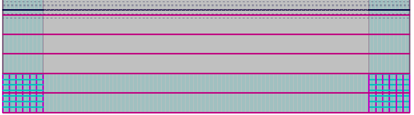
The final step in inserting the lines for our retrofit structure, are the new structural purlin lines.
Set the Line Type (eg Roof-Hugger purlin) then the spacing as determined by the existing purlins (5 feet) and select the Insert between Lines button. Select the lower existing purlin and the upper existing purlin and the new purlins are inserted.
Represented by the bold lines. If for any reason the new lines do not align perfectly with the underlying existing purlin spacing, the new lines can be deleted and reinserted or even manually moved.
Redo this same process for the opposite side of the roof and the project is ready to be bid and the material cut list produced. The line types should be checked and the best way to do this is use Tools > Show Line Types in the ISO view.
Select Cover > Flashings and the Select Trim dialog is displayed. Now that the new roof structural lines have been added to the model, they are listed as options. Select the required material to be installed on the new lines and then select Generate. A more detailed description of the function of generating flashings and trim can found in the Cover > Flashings section below.
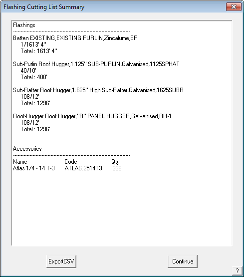
The correct material list is now displayed entirely automatically and with exactly the correct numbers for that job. The operator my now proceed to insert roof panels and roof trim for ridge and eaves over the job to complete the bid.
Comments are closed.