Digitising Options
Digitise Roof (3D)
The Construct Roof > Track Outline function contains both the track options and digitise options and the result is a 3D model of your roof based on the perimeter dimensions. It works differently to the Digitise 2D option described below in that all roof geometry (hips, ridges etc) are created automatically.
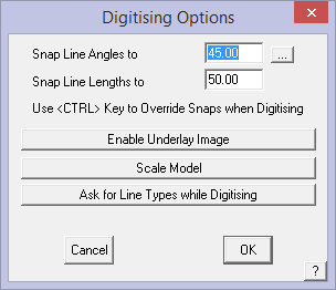
When you select the Digitise button and you will be prompted for the digitise options.
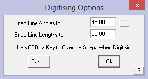
Set the Constrain the Angles to (typically 45°) and set the Constrain the Lengths to (typically 50mm or 2”) to ensure the roof model is square and as accurate as the image allows. For greater precision, simply reduce the constraint values, say 10mm or 1/2″.
Select [OK] and the cursor waits for you to select the origin or starting point, typically a corner of the building outline and you can start digitising the perimeter of the building outline using the left mouse button. You cannot use the middle mouse button to ‘snap’ to corners in the image as it is a pixellated image, it does not contain vectors (lines) or points to snap to. Do not start in the middle or part way along a wall or eave line.
While digitising the outline, you can also type exact line lengths into the prompt area and that line will be drawn at the precise length. You can also cancel ‘digitising’ and use the track outline Direction and Distance fields to complete the outline.
Remember, before you start digitising or tracing the perimeter of a PDF or an aerial image, you MUST scale the image using known reference lengths so that you are working at full size.
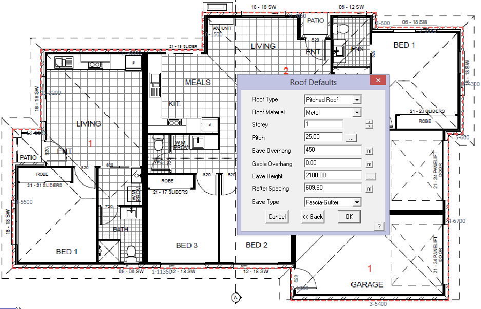

Work around the perimeter, scroll-zooming into each corner to locate it as accurately as you can, then at the penultimate corner, right click [Cancel], then [Close] and [Close Square]; then [Finish] and this brings up the Roof Defaults dialog. Fill out the variables as required, [OK] then [Continue] and the job is done.
It is also to a very high level of accuracy. This needs to be checked as usual and this is discribed in a previous section “The AppliCad Process”.
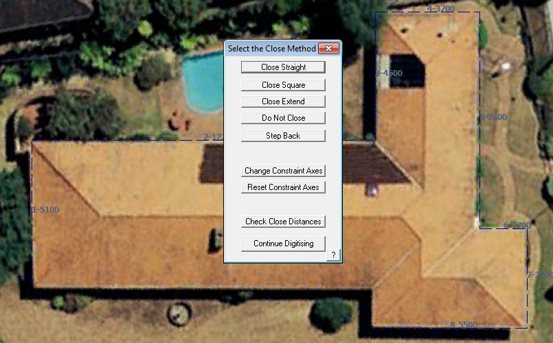
Close Option
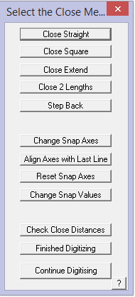
The [Close] methods are:
Close Straight – This simply joins the last point directly to the first point
Close Square – This creates another corner back to the original start point.
Close Extend – This extends the last direction to intersect the first wall.
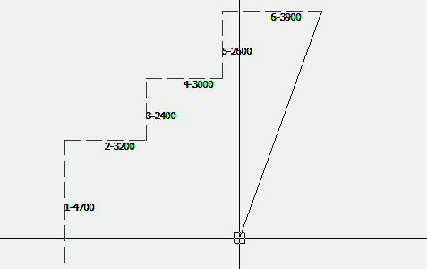
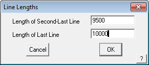
Close 2 Lengths – Prompts the user to close to a pre-defined line length eg: by specifying two close lengths at the penultimate line on this outline; select [Close 2 Lengths] and the operator is prompted for the specified close lengths, then the approximate location of the intersection point and the last two lines are drawn at the specified lengths.
Resulting in something like this:
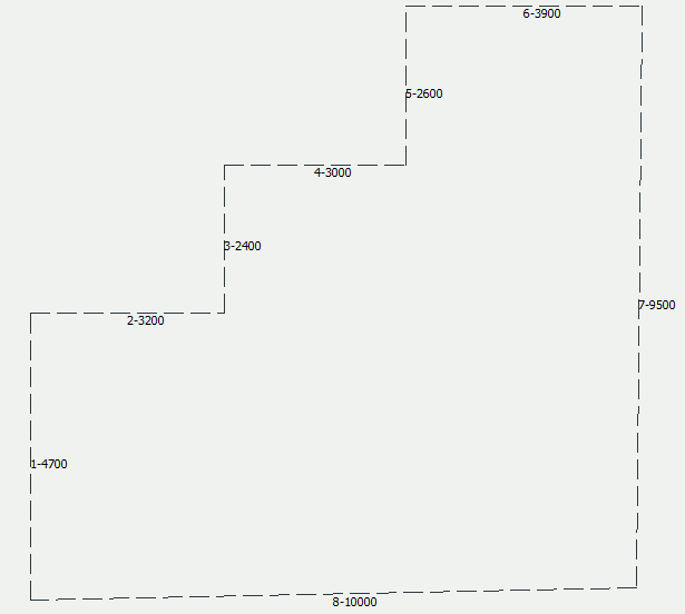
Which is clearly not square, but in accordance with the dimensions specified.
Step Back – Allows the operator to back track in the event that the line digitised is incorrect. The Ctrl Z keyboard short cut also takes you back one step.
Change Snap Axes – Allows the operator to change the direction of the Construction Plane (CPL) so as to continue digitising at a different orientation angle to the previously digitised lines. To access, when you need to change the CPL direction, right click the mouse and then select the option. The operator is prompted to select the origin of the new CPL, then the X axis of the CPL and then the Y axis of the CPL. Then select [Continue] Digitising. This may be repeated as many times as required until the job is completed. To finish, right click and select Close Straight or Close Square as required.
The CPL may be reset to normal model origin by selecting
Change Snap Axes – It is also useful to have the constrain angles set, typically to 45° so as to ensure that your outline is square at all corners.
Align Axes with Last Line – Rotates construction plane axes with last digitised line.
Reset Snap Axes – Resets the snap axes to original settings.
Check Close Distances – This command allows you to check the final two distances before you close the outline.
Finish Digitising – If there is a gap between the last and first points, then it does the same as the Close Straight method.
Continue Digitising – Lets the operator back into the digitise process.
You may also use the abbreviated method of typing C (for close-square) in the distance field, then enter. For a regular shaped structure, it is recommended that you input all but the last two lines, then use Close Square to close out the shape and let the software determine the last two lines for you. Notice that the length of the last two lines is displayed. Check that these match the plan and if they don’t, someone has made a mistake somewhere, either inputting the outline, measuring the roof or dimensioning the drawing. This is a quick and easy first check of your job.
Finish Option
Once the outline is fully defined and you are happy with the close distance, click the [Finish] button, or type F to finish the outline definition and go to the Roof Defaults dialog.
When you click Finish the wall lines are drawn and you are then prompted with the Roof Defaults dialog box. It is here that you define critical aspects of the roof geometry and it is important to note how these are linked with other Reporting stages.
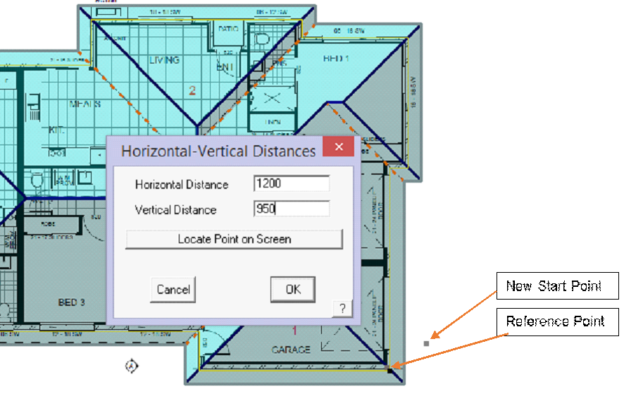
New Digitise Reference or Datum Point
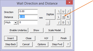
If you are tracking a subsequent roof outline (with an existing roof already on screen) and need to specify a start point, click the ‘o’ in the middle of the accelerator buttons:
You will be prompted to locate a Reference Point. Determine where the reference point should be and if it is the corner of existing geometry, you can ‘Snap’ to it with the middle mouse button. This does not create a new point, but uses the existing point that defines the lines at that corner – so it is exactly on the corner.
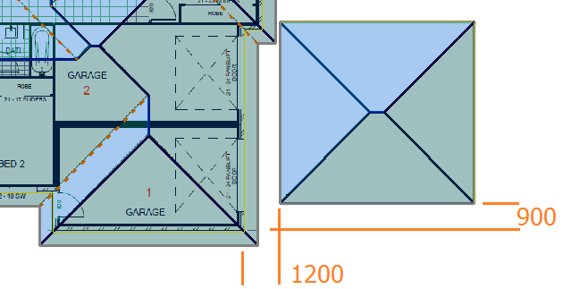
Type the offset value from the reference point to the new outline start point, (1200 over and 950 up), and when you start the new outline, this will be the new start point. Continue from there as usual.
Digitise Aerial Image – Slope Roof
The same process can be applied to aerial images. The three steps are:
1 Enable the image,
2 Scale the image and workspace, and
3 Start digitising.
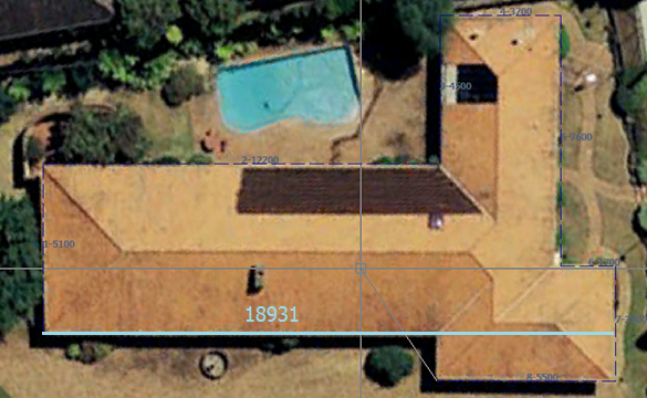
Select Enable Underlay and then paste from the clipboard or open a saved file. Remember, before you start digitising or tracing the perimeter of a PDF or an aerial image, you MUST scale the image using known reference lengths so that you are working at full size.
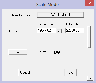
Scale Model using the overall dimension extracted from the aerial image provider’s tools.
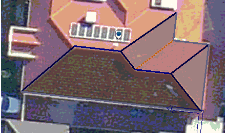
Digitise the perimeter and when you get to the penultimate corner, right click mouse [Cancel] and you will be prompted to close the outline.
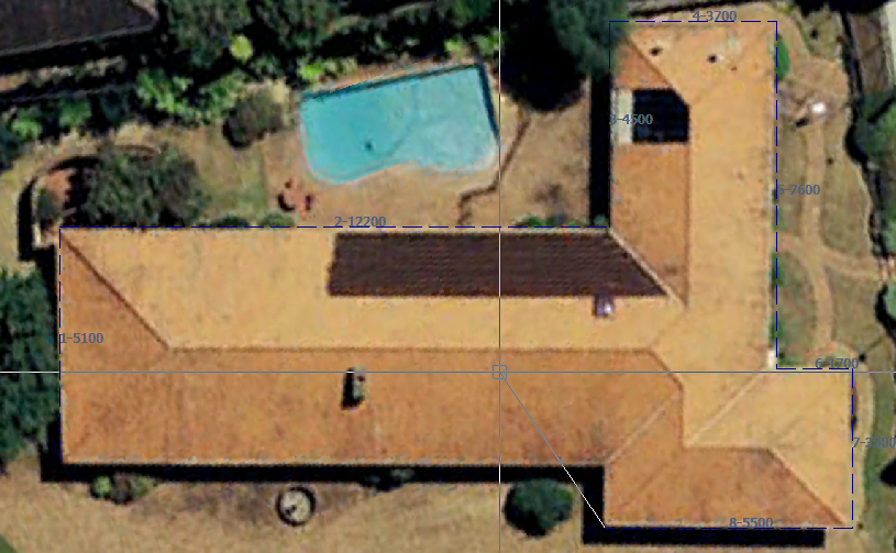
Typically you would select Close Square or simply type C for close.
The outline is closed out and then you are prompted for the details of the roof pitch and the overhangs etc.
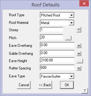
Set as required and select [OK].
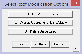
Add vertical features such as Gable Ends if you have any (this example does not) and select [Continue].
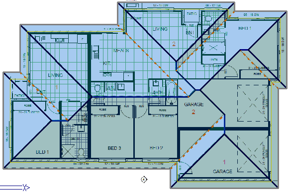
The 3D roof model is constructed. This is the quickest and easiest way to create accurate roof models that have regular roof geometry.
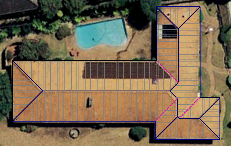
All the required AppliCad take-off functions will now work on this model for the most detailed and accurate client proposal.
This roof is complete then the image is turned off using the [Hide Image] button on the Track Outline dialog.
The 3D roof model is now displayed, ready for the rest of the checking and estimating process to be completed.
 Digitise Roof (2D)
You would use this command to digitise around a shape to create the outline for a roof plane or planes. The input method is simlar in function as Track-Outline (Single Slope Roof or Hip Roof) described above except the shape you draw defines the extents of single plane areas and the result is 2D geometry in the XY plane.
This process allows you to construct 2D geometry of roof shapes that may essentially be incorrect or cannot be built because the roof geometry doesn’t work through incorrect measurements or incorrect pitch or both. This may be due to skew of the aerial image or an architect’s design that is just plain wrong. As has been stated above, the software will report the areas and lengths as if the model was actually a 3D model.
Remember, before you start digitising or tracing the perimeter of a PDF or and aerial image, you MUST scale the image using known reference lengths so that you are working at full size.
You may digitise the outline of the roof by using various reference points or reference documents. These may include using one of the following methods:
know the (x,y) coordinates, or direction and length of the outline of the roof or wall lines
or
using existing CAD data (from an imported DXF file)
or
digitise the ‘blue print’ of the roof plan on a digitising tablet and apply a scale factor
or
digitise on a snapping grid by increments (the Grid command)
or
from an image extracted from a aerial photograph service such as Google Earth
or|
import an uncompressed bitmap image of a roof plan (such as a BMP, JPG, TIF or PCX file) as an underlay, prior to the digitizing the roof using the underlay as a reference and then apply a scale factor
or
directly from a Windows Clip Board image pasted into the AppliCad work space
or
from a PDF document from electronic plans.
Digitise From Images
Select the required Open Image File button and you will be prompted for the image. Select the image you wish to digitise from those you have previously captured and saved ready for quoting. To manage your images more easily, it is recommended that they be save as a BMP format image in the User folder. Except of course for those images pasted directly from the Windows ClipBoard.
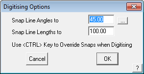
After you select the Construct Roof > 2D Roof Design > Digitise Roof option, the Digitise Constrain Values dialog is displayed. This provides for setting the digitised points to be constrained or ‘locked’ to multiples of the specified angle and lengths. Select values that best suit the accuracy and resolution of the image being used.
The constrain value is with respect to the positive X horizontal direction (ie from left to right on screen). The effect of constraining angles is to make “near” horizontal and vertical lines to be actually horizontal and vertical or multiples of the angle you inserted. So, if you set the constrain angle to 15 degrees, then the resultant line segments will be recalculated such that its angle with the horizontal will be an even multiple of 15 degrees.
The effect of constraining lengths is to make a line say, 997.334 mm long, to be 1000 mm long automatically. If you set the constrain length to 10mm, then the resultant line length will be rounded to the nearest 10mm.
![]()
Note: This process of constraining values also affects, Construct Roof > Dig-Outline; Modify Roof > Cut-out. You can disable constrain by entering 0 in either or both fields or by holding down the [Ctrl] key and digitising ‘off-grid’.
Select Enable Underlay Image.
The options are – Open Image or Paste from ClipBoard.
Understand what you wish to use and why before going to the next step. If you are not sure, try all processes and understand which one works best for your situation and image data supplied.
Open Image File – allows the operator to place the image onto the workspace on screen at an approximate scale, the model construction plane is then aligned to the image and the model geometry is created. The image and model space is re-scaled to correct size using the Scale Model function using the length of primary lengths in X and Y.
Paste ClipBoard Image – allows the operator to place the image onto the workspace on screen at an approximate scale directly from the Windows clipboard. The model construction plane is then aligned to the image and the model geometry is created. This is a very powerful tool, especially when used in conjunction with aerial image service providers such as Google™ (using the Google – Edit Copy Image function to clip the visible aerial image to the Windows clipboard) or PDF documents in Acrobat™ Reader (using the Acrobat Reader Edit Take a Snapshot function).
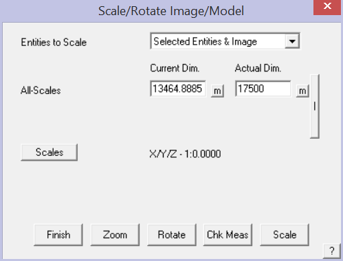
Once complete, the image/model needs to be re-scaled to correct size using the Scale Model function using the length of the longest edge that you have a measurement for. The longer it is the less the overall digitise error is. Refer to previous section for more details on Scaling Image/Model. It the image is not square to the edge of the screen hold down the Ctrl key to digitise off-grid.
Open Image File
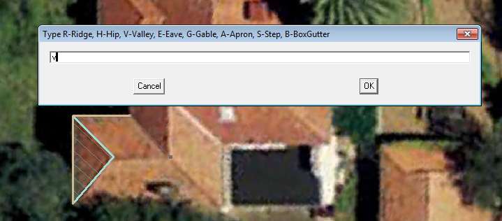
The 2D Digitise function works in a different manner to the 3D digitise function described above – primarily in the fact that as each line is digitised, the operator has the option to specify what line category each line is, that is whether the line is a ridge, an eave or a valley etc. in the pop-up box and select [OK] or type ‘Enter’ on the keyboard. Also, each and every line must be digitised following the underlay image. There is no automatic hip and valley line generation.
If the image is not square to the edge of the screen, and that is how you wish to digitise the job, then digitise the first line then right click, [Cancel] to bring up the Close Method dialog box which contains the option to Align Axes with Last Line – the digitising axis is realigned.
Then select [Continue Digitising] and all subsequent lines are input normally.
If you digitise a few lines that define a plane, you can use the middle mouse ‘snap’ function to lock onto the end of existing lines.
In this situation, the software will attempt to form a closed loop with the existing lines, but if too many options exist for a logical result, then the following screen pops up giving you the option to select the lines that define the required roof plane area.
Select the lines that define the remainder of the roof plane outline and the plane will be inserted.
Once a closed loop has been defined, the software them prompts for the plane material and the roof pitch.
The roof plane is inserted, bound by those lines. [Continue] digitising other roof plane areas until the roof is complete.
![]()
Remember that you can select a line end point off the grid snap, that is at an arbitrary point not aligned to the grid, by holding down the Ctrl (Control) key. Ctrl Z also works as a quick method of stepping back if you have made a mistake with the outline.
The Select Close Method dialog box also provides for realigning the digitising axes on the fly. Once the ‘off axes’ lines have been digitised, right click as if to close and select ’Reset Snap Axes’ to drop back to normal orthogonal snap axes.
You can also reset the Snap values from within the digitise process. Right click as if to close and select Change Snap Values to display the Digitise Options dialog and define new snap angles and line lengths as shown below.
Any plane inserted using this method can have the pitch modified using Mod-Roof > Change Pitch.
Before you start digitising you get the option to be prompted for the line type or not. If you opt for that latter (Do not ask for Line Types) then you must use Tools > Change Line Type to set the required line categories after the model is complete. This is simply a personal preference that best suits how you wish to work.
Digitise Aerial Image – Single Slope (Flat) Roof
The same process can be applied to aerial images. The three steps are:
1 Enable the image,
2 Scale the image and workspace, and
3 Start digitising.
Select Enable Underlay and then paste from the clipboard or open a saved file.
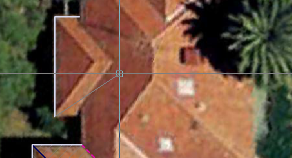
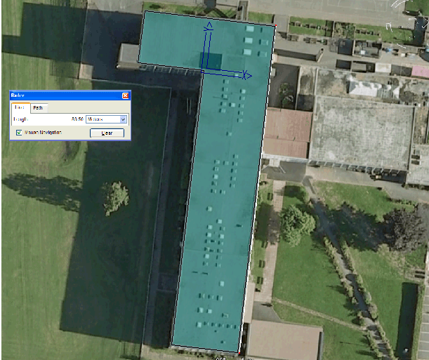
Scale Model using the overall dimension extracted from the aerial image provider’s tools. The software tries to do everything orthoganally so to set the overall measurement across the widest part of the building, hold down the Control (Ctrl) key to measure ‘off-grid’.
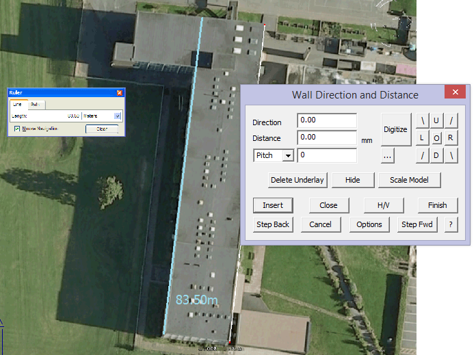
Digitise the first line, again holding the Ctrl key to insert the line off-grid; then right click [Cancel] and select [Close]. This brings up the Close Method dialog which provides for the option to re-align the digitise axes with the last digitised line. Select the function [Align Axes with Last Line]. The CPL or Construction Plane is re-aligned and you may continue digitising.
Digitise the perimeter and when you get to the penultimate corner, right click mouse [Cancel] and you will be prompted to close the outline; select Close Square. The Roof Defaults dialog is displayed and you set the Roof type to be Single Slope and the pitch as required. In this case it is zero.
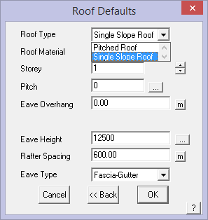
Select [OK] and you will be prompted for the pitching line. This roof is totally flat, so select [Continue].
And the job is complete. Notice the CPL icon is rotated and relocated. This occurred when we aligned the axes.
Comments are closed.