Contents
- 1 Set-Up
- 2 Pay Rates
- 3 Quote-Groups
- 4 Preference Settings
- 5 Tiles
- 6 Shingles
- 7 Shakes
- 8 Metal Panels
- 9 Flashings
- 10 Fasteners
- 11 Insulation
- 12 Tile-Colours
- 13 Metal-Colours
- 14 Tiles+
- 15 Flat-Sheet
- 16 Custom-Profiles
- 17 Membrane
- 18 Flashing Assemblies
- 19 Fixtures
- 20 Downpipes
- 21 Extra-Items
- 22 Area-Names
- 23 People
- 24 Curving-Charges
Set-Up
When Roof Wizard software is installed, basic generic materials and settings are provided to get you going. However, with software in 148 countries, it is impossible to have everything set exactly as each and every user wants and needs. You will need to make many additions and some adjustments. You will be using the files located in the C:\AppliCad\Roof Wizard\User folder or in a shared network folder mapped as a virtual drive. Generally they are a series of *CSV (Comma Seprated Values format files). Being CSV files you may use an editor such as Wordpad.exe or Notepad.exe to edit them, however, because the format is compatible with Microsoft’s Excel program and other spreadsheet software, you may prefer to edit them there. The huge advantage of editing in a spreadsheet program is the ability to make global changes to things like prices etc.
!!!However – keep in mind that the commands provided under the Set-Up options described below are designed to help you edit these files efficiently from within the Roof Wizard software and ensure that they are correct. If you are not competent or confident with using the spreadsheet program, stick with editing the files from within the Roof Wizard software. You can then rely on the result working properly when you’re finished editing the information.
The files in C:\AppliCad\Roof Wizard\Programs are best considered as a backup if you mess with the working copies in the ..\User folder and need to revert to something that works. If a file is required by the software and it doesn’t exist in the ..\User folder, for whatever reason (on first use or if it was deleted), the software will find the backup in the \Programs folder, use that and then create a copy in the ..\User folder. This provides a level of security should things go awry.
Note: For anyone updating from an older version during installation, the software will find the original version of your setup files and leave them there. If the format of a file has changed, for example material definitions for tiles, then the installation software will automatically convert the old format to the new format of that file.
In most cases there will be many additional items and adjustments to the software settings. This is usual and should not be seen as a chore – you do it once, check that it is correct and then you use it over and over every single day.

With the correct material and labour files set up, extracting the complete set of documents for the quoting, order, supply and installation of a job like this metal roof in Port Elizabeth, South Africa, takes about an hour.
Easy!
Your Company Details
The company details are the name and details that you want to appear automatically on your reports. You can define multiple business names in Roof Wizard for that situaiton where you have different branches or business units getting their estimating done by a centralised location.

The first step is to define the details of your company in the software, so that the reports print with your details on them. To define your company details select Set-Up > Your Company Details from the Pulldown menu. This will bring up the following dialog box.
From here you can type in the details of your company. When the details have been filled in click [Add], then [OK] and your company details will be saved permanently.
Name The name of your company.
Address The address of your company.
Phone The phone number of your company.
Fax The fax number of your company (if applicable).
Note 1 For additional information if required, such as company by-line or could also be used for second email address.
Note 2 For additional information if required – maybe the company’s web site address.
Business No. You could use this for your ABN (Australian Business Number), VAT No. or any other detail you wish to use. It doesn’t have to be a business number to be used on a report or header. Refer to the section dealing with defining templates to get a handle on how this information is used bythe software to generate reports.
Pay Rates
Set up > Pay Rates takes you to the Labour setup commands – specifically,
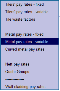
Tilers’ pay rates – fixed Allows you to setup fixed tile rates.
Tilers’ pay rates – variable Allows you to setup variable tile rates – with increments for storey and pitch interval.
Tile waste factors Allows you to setup tile waste factors.
Metal pay rates – fixed Allows you to setup fixed metal rates.
Metal pay rates – variable Allows you to setup variable metal rates – with increments for storey and pitch interval.
Curved metal pay rates Allows you to setup curved metal installation rates.
Nett pay rates Allows you to setup nett pay rates ie nett cost/m².
Quote Groups Allows you to setup Quote Groups.
Wall cladding pay rates Allows you to setup Wall cladding installation rates.
Tilers’ Pay Rates
Tilers’ Pay Rates – Fixed
This command displays the Roof Costing-Rates dialog box allowing you to set or change various quote rates and job cost rates associated with the estimate on a per square basis or per unit length. There is one rate regardless of pitch of the roof or storey number. The items are described below:
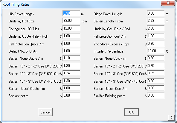
Hip cover length This value determines the number of hip tiles required. It is independent of the tile you selected.
Note that it is not used if you have supplied a hip tile length when you defined the tile using Set-Up > Tile.
Underlay/Sarking roll size This value determines the number of rolls of underlay.
Cartage per 100 tiles This value determines the total delivery cost. (Refer note below if you do not wish to have this displayed in the Supply and Install/Supply Only summaries.)
Underlay/Sarking quote rate This is the rate to quote underlay/sarking.
Fall protection quote This is the rate to quote fall protection.
Default no of units This is the default number of housing units for this job.
Batten 50×25 quote This is the rate to quote 50×25 battens.
Batten 50×38 quote This is the rate to quote 50×38 battens.
Batten 50×50 quote This is the rate to quote 50×50 battens.
Batten 75×50 quote This is the rate to quote 75×50 battens.
Batten User quote This is the rate to quote the user defined batten.
Ridge cover length This value determines the number of ridge tiles required. It is independent of the tile you selected.
Note that it is not used if you have supplied a ridge tile length when you defined the tile using Material > Tiles.
Batten length This is the length of battens per m2 of roof. It is used if you perform the estimate using the area method.
Underlay/Sarking cost rate This is the cost of the underlay/sarking.
Fall protection cost This is the cost of the fall protection.
2nd storey excess An extra value for second storey work.
Installers percentage The extra percentage to apply to the installers pay.
Batten 50×25 quote This is the cost of 50×25 battens.
Batten 50×38 quote This is the cost of 50×38 battens.
Batten 50×50 quote This is the cost of 50×50 battens.
Batten 75×50 quote This is the cost of 75×50 battens.
Batten User quote This is the cost of the user defined batten.
Waste per course The number of tiles you want to add per course if using the coursing method.
Waste – area method The number of extra pieces you want based on the total length of hips and valleys.
Sealant The rate per metre to add sealant to the trim. You define the finish of the ridges, gables and valleys etc as “Seal” to get a sealant value added to the Reporting dialog box.
Flexible pointing The rate per metre for flexible pointing.
![]()
Note: The cartage per 100 tiles variable described above will not appear in the Supply and Install dialog if the value is set to 0.
If a value is included, then it will appear and the value determined by the number of tiles ordered. If a value is set, then it will only appear in the material list summary if you have estimated for tile.
This will be added to the material list specifically for tile cartage, even if a value is also set for delivery under Areas – refer to Set-Up > Areas (where you can set delivery to not show). If you have both set, then both values will be displayed in the Supply and Install/Supply Only summaries. Typically you will have one or the other, but not both.
 Tilers’ Pay Rates – Variable
This command lets you define tile installer pay schedules based on storey, line-item and user defined pitch interval.
This Pay Rate is applied to the Tiles+ database when setup as described below and Tiles+ is selected as the database to use in System Preferences. You may define as many Tile-Pay rates as you need – for example, union or non-union rates; or sub-contractor A and sub-contractor B rates. Just remember, the more rates you set up the more you have to maintain if rates change, as they inevitably do.
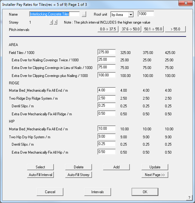
Name This is the name by which you select this pay rate in future.
Roof Unit The basis on which the costs are applied and the multiplier.
Storey This is the storey to which these values relate. You can have up to 10 storeys for the one pay rate.
Pitch intervals These values reflect those you set with the Intervals button at the foot of the dialog box. For each pitch interval value, you get a column of numbers associated with a line item. To edit a line item, highlight that column by clicking the pitch interval label.
Roof / sqm (sqFt) This is the installers rate to lay tiles on the roof.
…. The rest of the line items relate to hip, valley, gable and barge finishes you select under Cover > Select-tile.
Select This allows you to select an existing pay rate schedule.
Delete This allows you to delete an existing pay rate schedule.
Add This allows you to add a new pay rate schedule.
Update This allows you to update an existing pay rate schedule.
Auto-Fill Interval Automatically fills the table with the loading for each pitch interval.

Auto-Fill Storey Automatically fills the table with the loading for each storey.

Once the pricing table has the appropriate rates for each job function completely filled in, and don’t forget to do each storey, the file is saved away in the system using the “Add” button. Standard pricing files are stored within the software structure however user-defined pricing files are stored in a <filename>.DPT file format. In our example we created a labour pay rate file called “Interlocking Concrete Tiles” so this will be saved as InterlockingConcreteTiles.DPT.
Once the pricing table has the appropriate rates for each job function completely filled in, and don’t forget to do each storey, the file is saved away in the system using the “Add” button. Standard pricing files are stored within the software structure however user-defined pricing files are stored in a <filename>.DPT file format. In our example we created a labour pay rate file called “Interlocking Concrete Tiles” so this will be saved as InterlockingConcreteTiles.DPT.
The <filename>.DPT file is saved in a text file which allows you to make changes in an external program such as Notepad or Wordpad, or indeed, a spreadsheet program such as Excel. This is useful if you have major changes to pricing across the board and changing the values in columns is a whole lot easier in Excel if you know how. For the rest of us, open the pricing file in AppliCad (Costing > Tile-Pay) and do it long hand, one item at a time. Once complete don’t forget to select “Update” and the changes will be saved.
Interval Labels
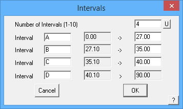
Customers utilising the GRIM output feature of AppliCad to link the estimation process to downstream systems have often had to create duplicate mappings of labour rates due to the output of variable labour rates in the Roof Wizard software. Outputs such as Ridge (1, 22.5) where the 1 specifies the storey and 22.5 specifies the pitch have had to create multiple mappings for each pitch gradient in 0.1 degree increments. In 8.2, we have provided the ability for each pitch interval to be given as a label (e.g. A, B, C as can be seen in the attached image) with the output therefore being Ridge (1,A), or Ridge (1,B) etc. This greatly reduced the number of mappings required, thus reducing the workload for our users and speeding up the interface between systems.
Labour Item Descriptions
Labour Setup (Tiles Database)
NOTE: The following description for setting up labour rates applies to Roof Wizard V11.0 and up.
If you’re not using Tiles+, DO NOT use LabourFile.DAT (as described below for Tiles+) for the regular Tiles database. Things go awry and it is difficult to undo.
The standard labour items are described in the file TileLabourMenus.DAT.
The file looks like this when viewed in Notepad:

Roof name, Hip, then Ridge main name followed by 2 additional options (these are added to the price of the main Ridge/Hip line); then Valley main name and again 2 more pricing options, additional to the Valley price. Gable has 3 additional line items, not 2 like the rest. Underlay, Apron, Batten, Counter Batten, Fall Protection and Downpipes follow.
Note: All items must stay in their relative positions in the list.
Once setup as described above, the pay rate structure looks like this (the rates displayed below are random):

Once defined, set a name, then select [Add] to create a new labour rate, or [Update] to change the rates. Once added, these values are saved to the file TLabour5.csv in the ..\User folder.
Further rates are added to this list as you define them based on your settings for Storey Interval and and Pitch Interval. If you hit the [Update] button, you must next select [OK] to quit so that the file is saved as you exit.

At the bottom of this CSV file are the item labels as defined for your labour rates:

For the Tiles database, select your pre-defined pay rate here:

The selected tile details dialog for Tiles data file.
![]() Note: Should the pay rate be changed for any reason after you have selected it, then you must reselect the rate. Indeed, this applies to any database of materials or Reporting – if it is changed, you must re-select it and re-calculate the labour and materials costing.
Note: Should the pay rate be changed for any reason after you have selected it, then you must reselect the rate. Indeed, this applies to any database of materials or Reporting – if it is changed, you must re-select it and re-calculate the labour and materials costing.
When you calculate the tile quantities, either by area or coursing, the rates flow through to the Supply and Install summary of costs.
Labour Setup (Tiles+ Database)
Available when using the Tiles+ database setup, is the ability to define the Labour item descriptions. These definitions are stored in a text file called LabourFile.dat and may be created or edited in a text editor such as Notepad or Wordpad.
The quick way to create the user defined group description file is to copy the file “LabourFile.TMP” to “LabourFile.DAT” in Windows Explorer, and then make any modifications using a Windows-based text editor such as NotePad or WordPad. Only attempt to edit this file if you are proficient in the use of the editor program. To return to standard groupings, the user must remove the file “LabourFile.DAT” so that the “LabourFile.TMP” in the user directory is found instead. You might also open LabourFile.TMP in the editor and use File | Save-As to create the LabourFile.DAT with your new descriptions and charges.
This will handle every permutation of Reporting for your tile item installation options.
The format of the LabourFile.dat:
#Tile Labour File
#Line above must remain in file for it to be located by software
#Format 0=Header, 1=Main Cost, 2=Add Cost > Group Description > Reporting Calculation Method 1=Area, 2=Len |Group - see below
#1 = Field Tiles, 2 = Ridge, 3 = Hip, 4 = Valley, 5 = Verge, 6 = Eaves, 7 = Abutments, 8 = Aprons, 9 = Box Gutters, 10 = Battens,
11 = Counter Battens, 12 = Insulation, 13 = Sarking/Underlay, 14 = Fall Protection, 15 = Downpipes, 20 = Extras
#Last option defines whether default is to include in Pricing or not 0=No, 1=Yes
0|AREA|0|1|0
1|Field Tiles|1|1|1
2|Extra Over for Nailing Coverings Twice|1|1|0
2|Extra Over for Clipping Coverings in Lieu of Nails|1|1|0
2|Extra Over for Clipping Coverings plus Nailing|1|1|0
0|RIDGE|0|2|0
1|Mortar Bed & Mechanically Fix All End|2|2|1
1|Two Ridge Dry Ridge System|2|2|0
2|Dentil Slips|2|2|0
2|Extra Over Mechanically Fix All Ridge|2|2|0
0|HIP|0|3|0
1|Mortar Bed & Mechanically Fix All End|2|3|1
1|Two Hip Dry Hip System|2|3|0
2|Dentil Slips|2|3|0
2|Extra Over Mechanically Fix All Hip|2|3|0
2|Arris/Bonnett Hip|2|3|0
2|Mitred Hip|2|3|0……………….etc
Below is a screen shot of the file we created for the demonstrating the function. Notice the header of the file shows the order in which the information must be input. Once setup, you have total control over the descriptions you use for each labour item. This includes whether the labour relates to Field tile, ridge or hip etc, the description and the cost per area or per length.
The “LabourFile.DAT” file has the following format, as outlined in the header of the file:
# = Comment Line
A|B|C|D|E = Data Line, where:
A 0 = Header Line
1 = Main Cost
2 = Additional Cost
B Line Item Description
C 1 = Item to be priced by Area
2 = Item to be priced by Length
D 1 = Field Tile Category
2 = Ridge Tile Category
3 = and so on, see documentation
E 0 = Do Not include in pricing calcs by default
1 = Include in pricing calcs by default.
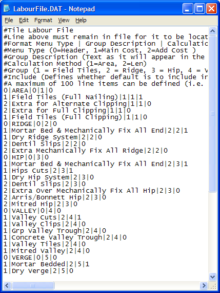
Screen captured from the LabourFile.dat being edited in Windows Notepad
The pay rate is selected when the tile is selected to cover the roof under the Cover > Tiles command.
Apart from the labour costs that can be associated with any particular accessory or component under the Set-Up > Tiles+ setup, it is expected that most users will want to set up labour options based on the Set-Up > Set Up Pay Rates > Tilers’ pay rates – variable (not Tile-Rates) menu which permits the user to associate costs to tile profiles and have these costs cross-referenced with the relative pitch and storey of any given roof plane it is joined to. You may define as many labour files as you need for different profiles, different sub-contractors or different geographic areas – whatever works for your business. Refer to the Reference Manual section on Cover > Tile-Pay for more details on setting up the pay rates.
Once the labour rate is defined, the labour pay scale for the installation of a job is set when the tile profile is selected under the Cover > Tiles command.
The Labour Setup for Tiles+ is very extensive and allows the user to operate in one of 2 modes; either using the standard grouping descriptions as released with the software, or to create user defined grouping descriptions to suit your circumstances. The grouping descriptions are set up in a file you create that must be called “LabourFile.DAT” as described above.
The existence of this file in the user directory of the software determines whether the user wishes to use user-defined grouping descriptions in the Set-Up > Set Up Pay Rates > Tilers’ pay rates – variable menu as opposed to the standard grouping descriptions as released with the software. If it does not exist (because you didn’t define new grouping descriptions) the file provided with the software by the name of “LabourFile.TMP” is used instead, resulting in the descriptions shown below left. The difference is most easily explained by reviewing the 2 resultant dialog boxes.
For the Tiles+ database select it here:
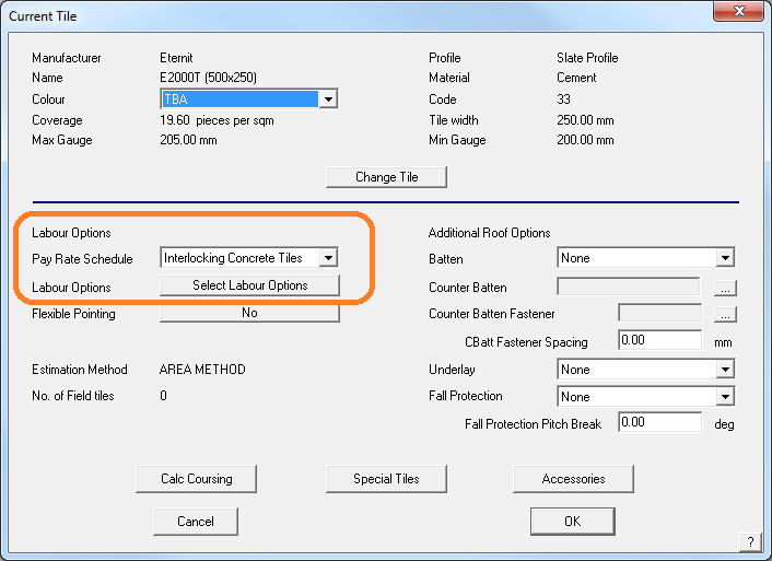
The selected tile details dialog for Tiles+ data file.
Below are examples of the result of setting up your own defined labour rates.
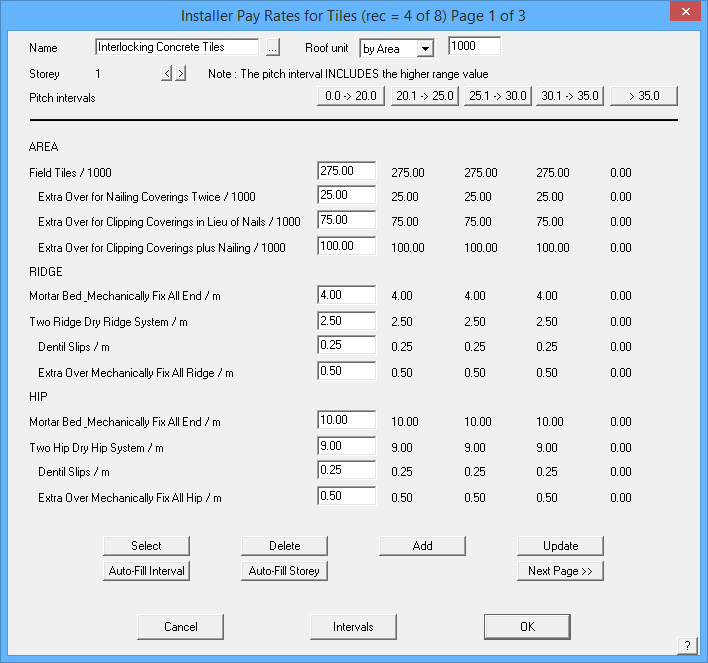
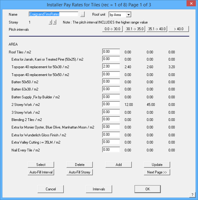
Click the down arrow for a drop down list of available pay scales that you have defined.
![]() Note: Should the pay rate be changed for any reason after you have selected it, then you must reselect the rate. Indeed, this applies to any database of materials or Reporting – if it is changed, you must re-select it and re-calculate the costing.
Note: Should the pay rate be changed for any reason after you have selected it, then you must reselect the rate. Indeed, this applies to any database of materials or Reporting – if it is changed, you must re-select it and re-calculate the costing.
Remember: After creating a new labour file, test it on a simple job to ensure the descriptions are transposed correctly. If it works correctly, then you are ready to use it on real jobs. This is a good tip whenever you change or update a data file, whether a labour or material data file.
Each dialog box demonstrates the value for each respective field for a pitch interval as well as a given storey. Thus, various values can be entered to allow for different pitch and storey rates often charged by sub-contractors working on a job. The “Auto-Fill Interval” and “Auto-Fill Storey” buttons assist in the filling in of values across the dialog by allowing the user to specify a percentage increase from the first interval / storey and to automatically fill the other fields in the dialog box with the modified values.
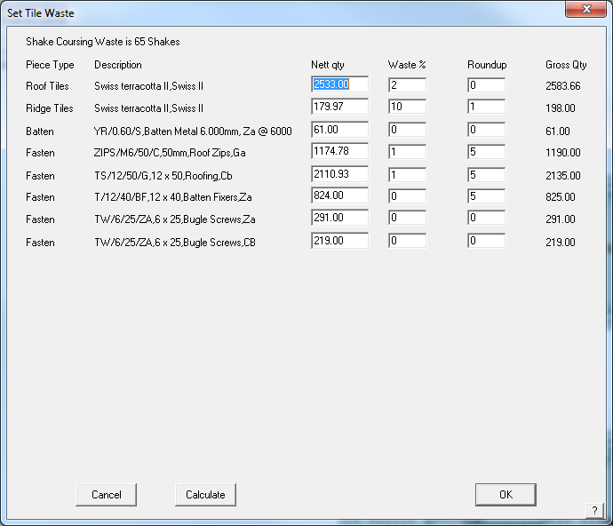
 Tile-Waste
This command displays the Tile-Waste dialog box allowing you to set or change the wastage factors for different tile items.
The tile wastage values are calculated in the following sequence:
The nett number of field tiles is first calculated,
Then the number of extra pieces per course is added,
Then the extra number of field pieces per length of hips and valleys is added (field pieces per metre or per foot of hip and valley),
Then the percentage waste of field pieces is added,
Then the total number of field pieces rounded to give the final number.
Each waste value is applied in turn. If you do not want a particular waste factor to be applied then set the value to zero.
The first option – Extra Field Pieces (per course) is a number or decimal fraction, of a tile to add at the end of each course line to account for waste as a result of typical job variables such as breakages. The more course lines, the more field pieces that are added to the total tile count.
Extra Field Pieces (per length of hip and valley) is applied as a result of the total length of hip and valley combined and expressed as pieces or decimal fraction of pieces, per metre (or foot) of hip and valley. This is typically used to account for extra tiles that may be required as a result of breakages during cutting of tiles to fit at hips and valleys.
The more cuts there are, often the more breakages there are. No account is made for the re-use of the off-cut, as is sometimes possible with metal tiles.
If the off-cut is reused as a matter of course, then this needs to be taken into account and the number reduced. Experiment with different values until you get the correct result based on your experience.
All other fields are individual values for each category of tile piece. Waste % takes the total number calculated based on the course lines and adds the specified percentage and then rounds up to the nearest value as specified. A value of zero does not round up.
Multiple configurations of tile wastage and rounding of elements can be specified and saved into various configuration files. These files can now be linked to each tile record, thus allowing improved streamlining of waste and rounding calculation without requiring the estimator to remember to modfiy these values. Select [Save-As] to save the tile waste file and select [Load] to load a previously defined set of values.
When you click [OK], the values are saved. These values are applied to the tile calculations when the Reporting > Supply+Install is selected. A summary of the tile waste calculations is then displayed when you select Tile-Waste from the Supply+Install or Supply-Only dialog box.
Metal Pay Rates
Metal Pay Rates – Fixed
This command displays the Roofing Labour rates dialog which allows you to set installation rates for different categories of roofing items on a per square or per unit length basis. There is one rate regardless of pitch of the roof or storey number. The following table describes the rates:

Labour Rate |
Description |
Straight roofing per m2 |
The rate to install straight sheeting on the roof (or verandah) |
Insulation per m2 |
The rate to lay the insulation |
Ridges/hips per m |
The rate to install the ridges and hips |
Valley per m |
The rate to install valley flashing |
Fascia only per m |
The rate to install fascia flashing only |
Gutter only per m |
The rate to install gutter only |
Fascia barge per m |
The rate to install fascia on a barge |
Fascia and gutter per m |
The rate to install fascia and gutter together |
Barge per m |
The rate to install barge flashing |
Apron per m |
The rate to install apron flashing |
Batten per m |
The rate to install battens |
Each Downpipe |
The amount to install each downpipe |
Each chimney |
The rate to cater for each chimney |
Labor markup % |
The percentage the total labour cost will be marked up in the final costing |
Labour quantities |
This is either “NETT values” or “GROSS values”. Nett values are the geometric values of the roof. Gross values are the quantities of materials you order. Setting the method here will effect the quantity you see in the Reporting dialog boxes later. They only apply to metal roofing and metal flashing quantities for all methods of labour calculation – fixed and variable. |
Siding per sqm |
The rate to install siding per square metre |
Wall top per m |
The rate to install wall top flashing |
External corner per m |
The rate to install external corner flashing |
Internal corner per m |
The rate to install Internal corner flashing |
Door head per m |
The rate to install door head flashing |
Door edge per m |
The rate to install door edge flashing |
Box gutter per m |
The rate to install box gutter |
Curved roofing per m2 |
The rate to install the curved sheeting on the roof (or verandah) |
Each curved sheet |
The amount to add for each curved sheet |
Per curved apron |
The amount to add for each curved apron (bullnose verandahs) |
Per curved barge |
The amount to add for each curved barge (bullnose verandahs) |
Per curved hip |
The amount to add for each curved hip (bullnose verandahs) |
Per curved valley |
The amount to add for each curved valley (bullnose verandahs) |
Curved apron per m |
The rate to install curved apron (bullnose verandah) |
Curved barge per m |
The rate to install curved barge (bullnose verandah) |
Curved hip per m |
The rate to install curved hip (bullnose verandah) |
Curved valley per m |
The rate to install curved valley (bullnose verandah) |
Roof removal per m2 |
The rate for roof removal |
Gutter removal per m |
The rate for gutter removal |
Material markup % |
The rate to markup the material costs for the final quote |
Wall base per m |
The rate to install wall base flashing |
Window sill per m |
The rate to install window sill flashing |
Window head per m |
The rate to install window head flashing |
Window edge per m Wall Batten per m |
The rate to install window edge flashing The rate to install wall battens per metre |
After you make a change and click [OK], the changes are saved in rates.bin for use in all future jobs.
If you click the Pitch Allowance button the Pitch Allowances dialog box is displayed.
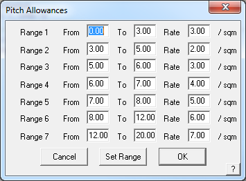
Here, you set the pitch ranges as well as the rate to apply for planes in that range. When you click Set Range, you can change the number of ranges. The maximum number of ranges you can have is 10.
These values are used in the labour charge calculation under Reporting > Supply+Install. Each plane in the model is tested for its pitch and area, and based on the roof pitch, the above table is used to derive a pitch allowance. The individual pitch allowances are added together to derive the total pitch allowance.
![]() Note: If the Set Up > Set up Pay Rates > Metal Pay Rates Fixed option of “Labour quantities” is set to “Use NETT values,” the labour rates for fascia and gutter are combined under Supply & Install > Labour SubTotal into a single line item of “Fascia and gutter m.”
Note: If the Set Up > Set up Pay Rates > Metal Pay Rates Fixed option of “Labour quantities” is set to “Use NETT values,” the labour rates for fascia and gutter are combined under Supply & Install > Labour SubTotal into a single line item of “Fascia and gutter m.”
If the “Labour quantities” is set to “Use GROSS values,” the labour rates for fascia and gutter are kept separate under Supply & Install > Labour SubTotal as “Fascia only m” and “Gutter only m.”
Metal Pay Rates – Variable
This command displays the Installer Pay Rates for Metal roofing box allowing you to set or change various labour rates associated with the installation of metal roofing. You select a pay-schedule for a job on the Cover > Select-metal dialog box. The maximum number of different labour rate tables is 50.
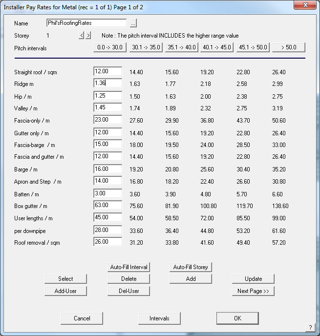
Name This is the name of this pay schedule.
Storey This is the storey to which the following rates apply. A schedule can have up to 10 storeys.
Pitch Intervals These are the pitch intervals you want to set for the job. You set them by clicking the Intervals button at the foot of the dialog. To edit a column of values you need to click on the interval value.
Line items For each line item you need to enter the rate per unit area or length for that line item. For roof removal and gutter removal only the first rate is actually read when the Reporting is performed.
Select This button lists up the existing schedules. You then select the one you want for editing. After selecting a schedule, the Update button appears letting you update the schedule.
Delete This button lets you delete the currently selected schedule.
Add This button lets you add the current schedule (schedules must have unique names).
Update Updates the currently selected table with changes.
Special Pay Rates
Add-User Allows you to add any sort of labour charge that applies to your flashing and trim. Each new item is given a unique index number. The example below shows a new rate for ‘Tear-off and clean up’.

You might also set up a special rate for any flashing item that has extra processes that changes the cost compared with regular trim, say scribing hip caps or caulking ridge ‘Z’ bars. This new labour option will be available when you define the flashing item and select the Pay Rate Schedule. The alternate pay rate will be available to use. First select the variable pay rate with the special rate in it, then select the special rate.
Note: If no special labour options are required, then you do not need to set these up as it adds a further level of complexity when setting up your flashings.
Delete User Allows you to delete a user defined charge. You will be prompted for the index number of the item to delete.
The example below shows a new rate for ‘Special Gutters’.
Del-User deletes the new rate.
Next/Previous Page These buttons allow you to toggle between the two available pages.
[Cancel] Closes the dialog box without saving the changes you have made.
Intervals Lets you define the pitch intervals you want to use – see below, Interval Labels.
[OK] Closes and saves the changes you have made.
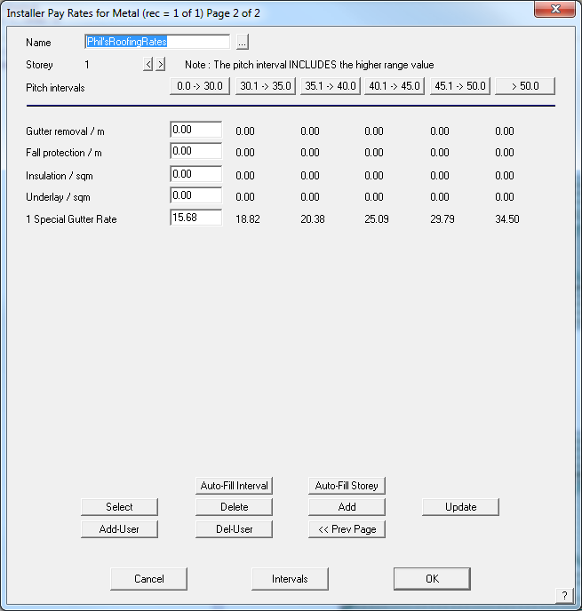
User defined pay rate for Special Gutters
Interval Labels
Customers utilising the GRIM output feature of AppliCad to link the estimation process to downstream systems have often had to create duplicate mappings of labour rates due to the output of variable labour rates in the Roof Wizard software. Outputs such as Ridge (1, 22.5) where the 1 specifies the storey and 22.5 specifies the pitch have had to create multiple mappings for each pitch gradient in 0.1 degree increments. In 8.2, we have provided the ability for each pitch interval to be given as a label (e.g. A, B, C as can be seen in the attached image) with the output therefore being Ridge (1,A), or Ridge (1,B) etc. This greatly reduced the number of mappings required, thus reducing the workload for our users and speeding up the interface between systems.

When you click [OK], the rates you defined are saved for future use. You may set up as many different files as you have different pricing for different profiles or wall systems.
Curved-Metal-Pay Rates
(Pulldown Menu)
This command displays the Installer Pay Rates for curved metal roofing box allowing you to set or change various labour rates associated with the installation of curved metal roofing. You select a pay-schedule for a job on the Cover > Select-metal dialog box.
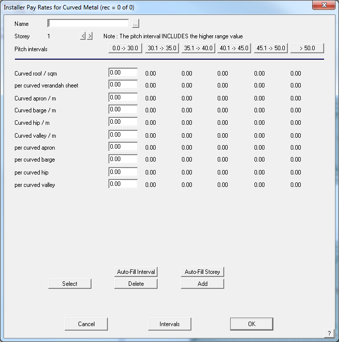
Name This is the name of this pay schedule.
Storey This is the storey to which the following rates apply. A schedule can have up to 10 storeys
Pitch Intervals These are the pitch intervals you want to set for the job. You set them by clicking the Intervals button at the bottom of the dialog. To edit a column of values, you need to click on the interval value.
Line items For each line item you need to enter the rate per unit area or length for that line item. For roof removal and gutter removal, only the first rate is actually read when the Reporting is performed.
Select This button lists the existing schedules. You then select the one you want for editing. After selecting a schedule, the Update button appears letting you update the schedule.
Delete This button lets you delete the currently selected schedule.
Add This button lets you add the current schedule (schedules must have unique names).
[Cancel] Closes the dialog box without saving the changes you have made
Intervals Lets you define the pitch intervals you want to use
[OK] Closes and saves the changes you have made.
Nett-Rates
(Pulldown Menu)
This command displays the Roofing Reporting rates for nett-only roofing dialog which allows you to set the rates for the Reporting > Nett-Only command.
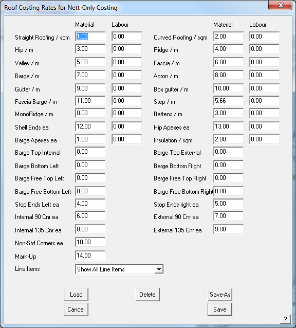
The values you set here are used by the Nett-Only Reporting method, to provide you with a quick and easy way to develop a quote using a pricing approach (rather than a cost up process).
Load Loads a predefined set of Net-Only rates for specific roof systems.
Save-As Saves a Nett-Only pay schedule for specific roof systems.
Here we present you with the option to supply material and labour rates for different parts of the job, which are multiplied by the nett quantities for the job (the nett quantities relate to the quantities displayed by the Tools > Tally-Quantities command). You can choose to set a rate to something meaningful or leave it at zero, and therefore has no impact on the quote.
So, if you have a rate per unit area you use to quote a job with, then this is the quickest and easiest method.
When you click [OK], the rates you defined are saved for use by the Reporting > Nett-Only command.
 Wall Cladding Pay Rates
This function sets the installation pay rates for all components of walls and wall trim. They are all based on a cost per metre or cost per foot (depending on your units of measurement.

Name This is the name by which you select this pay rate in future.
Storey This is the storey to which these values relate. You can have up to 10 storeys for the one pay rate.
Select This allows you to select an existing pay rate schedule.
Delete This allows you to delete an existing pay rate schedule.
Add This allows you to add a new pay rate schedule.
Update This allows you to update and save changes to an existing pay rate schedule.
Auto-Fill Interval Automatically fills the table with the loading for each pitch interval.
Auto-Fill Storey Automatically fills the table with the loading for each storey.
Add-User Allows you to add any sort of labour charge that applies to walls. Each new item is given a unique index number.

Delete User Allows you to delete a user defined charge. You will be prompted for the index number of the item to delete.
Once the pricing table has the appropriate rates for each job function completely filled in, and don’t forget to do each storey, the file is saved away in the system using the “Add” button. if it is a new file; select Update if you’re changing details in an existing file.
Standard pricing files are stored within the software structure however user-defined pricing files are stored in a file called – SidingLabour5.csv.
When you click [OK], the rates you defined are saved for future use. You may set up as many different files as you have different pricing for different profiles or wall systems.
Quote-Groups
(Pulldown Menu)
The Quote-Groups option is a very powerful tool for controlling how much detail you supply the prospective client in your quotation or proposal. A quote group is a list of roofing items you want to group together on a quotation under a single price effectively ‘hiding’ individual line item prices.
The option is selected under Set-Up > Set up Pay Rates > Quote Groups.
For example, perhaps you want to provide a price for the roofing components (roof, ridges, hips and gables) and another price for the fascia and gutter (which may include valley and downpipes too).
- Create a quote group for each group of roof material categories;
- Review the price for that quote group (from the Reporting > Supply+Install > Quote Groups on-screen report).
- Print the report (you need to ensure that the key text string for each quote group is on the report template). For more details about editing Templates, refer to this section.

The list of line items that will appear in the list is stored in a pre-defined list as this was how the software was initially setup to work. Over time it became apparent that users wanted their own list, or have the items in a different order and the method of setting this up is described later – Customising Quote Groups.
CREATING A QUOTE GROUP
Step one in creating a quote group, you need to:
Enter a group name Enter a key text string (this is automatically generated for you as ###QGROUP1-n where the number refers to the group number).
NOTE: You can have a maximum of 20 Quote Group definitions, with a maximum of 50 items per quote group.
The Quote Group with “Remainder” in it must be the last quote group, otherwise the remainder gets swallowed up in the calculation and nothing flows through to the next group for Labour.
You must decide if you want the group name reported as well as the price, whether you want the tax amount to be displayed, will the final price include or exclude tax, whether it will include the mark-up percentage and if you want labour included.
Select the roofing material categories you want to be part of this group by clicking the button to the right of the category name. This button will then toggle to [Yes] and an asterix (*) or star symbol will appear alongside the category name. Enter a description for this category as you wish it to appear on the quotation report. If you don’t enter a description, the price of that category will be added to the total for the group but will not be reported as a separate item on the report.
Once the list is complete, you then select [Add], and that Group is added to the system database and effective for all subsequent jobs.
From the dialog you can easily select, update and delete an existing quote group. From the Reporting > Supply+Install dialog, you can see the results of the quote group by clicking the [Quote-Groups] button. The report for quote group 5 will be displayed and appear similar to the dialog box below:

This shows the line items which will be displayed, the calculated total, the material total and the labour total. You can also edit the bottom line price to a new value if you wish. The button to the right of the price field lets you set whether this price includes or excludes tax.
When you print the report, this group will be swapped for the key text string “###QGROUP5”.
Key Text strings are also created under the Key-Text String category of Quote Groups relating to the name of the quote.
These Key-Text Strings allow you to separate out the Material and Labour components of the quote group as well as the total price without the breakdown associated with the ###QGROUP Key-Text Strings.
| Key text string | Description |
| ###QG”QGName”-MatSubTotal | Sub-total of Materials for specified Quote Group name |
| ###QG”QGName”-LabSubTotal | Sub-total of Labour for specified Quote Group name |
| ###QG”QGName”-Total | Total of Materials and Labour for specified Quote Group name |
For example the above Quote group (Roofing) you will have the following Key Text Strings created, ready for you to insert into your report template:
###QGRoofing-MatSubTotal Gives you the Material Subtotal for that Quote Group
###QGRoofing-LabSubTotal Gives you the Labour Subtotal for that Quote Group
###QGRoofing-Total Gives you the Total price for the Quote Group
Preformatted tables are also available as Key Text Strings:
Key text string Description
| ###CostingDetailsTableQG | The costing details table is drawn with its top left corner at the origin of this text. Note that the width of the table is a fixed size. Items are grouped according to Quote Group definitions. |
| ###CostingDetailsTable1QG | This is the same as the costing details table above, but only reports the category, description and quantity and omits the costing fields. Items are grouped according to Quote Group definitions. |
| ###CostingDetailsTable2QG | The costing details table full format with tax is drawn with its top left corner at the origin of this text. Note that the width of the table is a fixed size. (Cost Price) Items are grouped according to Quote Group definitions. |
![]()
Note: All the Key-Text Strings are described here.
Customising Quote Groups
Quote Group Items List
The standard list before any alternative list is created has the items shown below:

If you wish to set up a different list or change the order of the list, you can do so by defining a new list and saving it as a file called QuoteGroups.DAT – a text file created in a text editor such as Notepad. The items in the list will come from the original list or from Alternate Categories list, and if you don’t want to itemise everything, list the key items and then use ‘Remainder’ as a list item and everything else will be included in this item in the group.

New item names can be created and this is described using AltCategories described below:
A good starting point for a QuoteGroup setup might be a Fascia and Gutter group and a Roof group and that QuoteGroup file would look like this:
QuoteGroups (if you wish you could copy this file and save it to your ..\User folder.)
and the custom list for this quote group would require the QuoteGroup.dat file set up as described above.
Remember, as stated above, the Quote Group with “Remainder” in it must be the last quote group in your list of groups, otherwise the remainder gets swallowed up in the calculation and nothing flows through to the next group for Labour rates.
Editing the Quote Groups
The Quote Groups dialog is comprehensive and in some situations, may be simply too much information being reported on individually. The Quote Groups are stored in the text file created by the software called QuoteGroups.csv (a CSV file is a Comma Separated Values format that may be read in Excel) where the groups can be defined.
The setup of the Quote Groups may be substantially simplified by editing the file in a text editor such as Wordpad or Notepad which are Windows utility programs. However, for most users MS Excel will be the preferred editor, and when opened will look like this:

The structure is obvious and allows you to be very creative in how you build your client quotations or export job data to other systems, within limits. The Index number is extracted from the QuoteGroups.DAT file, the list of Quote Group category items. The category names are used in the picking up of items, as this is more useful to specify items exactly. Unless you specify a category name in the DAT file and select it to be included for a specific group, it doesn’t include it. Add any new categories you need to the end of the list instead of trying to make everything alphabetical or grouped or the index number doesn’t line up with the category.
Export Pricing Data by Category
Roof Wizard is moving towards an improved pricing and job management solution, with linkages to external accounting systems, a requirement to allow splitting up of an estimate into various groupings became apparent. The best way to do this is with Quote Groups, and so the ability to modify the default “category” for each material item in the software has been provided for on each data entry dialog box.
To further fine tune your reporting of material and labour items, you can define an Alternate Category. This allows you to define a different category so that the tile (in this example) may be listed under a different group in the [Supply Only] or [Supply and Install] summary list.

For example, here we need a snow retention bar included in the Fascia and Gutter Quote Group. So we change the definition of the part to show as an Alternate Category – Snow.

When we go to Reporting > Supply Only/Supply and Install, we can see that the Snow Strapsare in our material list, but also have an Alternate Category “Snow”.

So now we can add “Snow” items to our Quote Group.

Once included, this item and the cost for this item will be included in the Fascia and Gutter Quote Group as a single aggregated sub-total cost.
There are limits – you can have a maximum of 20 Quote Group definitions, with a maximum of 50 items per quote group.
Note: All items that are not specifically listed in a Quote Group will automatically be added to a Quote-Group called Remainder.

Preference Settings
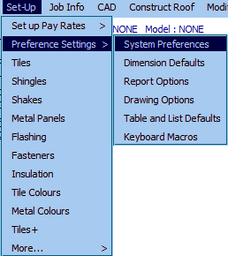
System Preferences
This command sets various operator preference settings such as the units, slope input and terminology of your installation. You should only have to set these options once. There are a lot of options here and setting them incorrectly may change the way the software works for you, so be sure you understand what you’re changing, and why, before you change it.
When you select System Preferences, the Preferences dialog box is displayed:

- Left column of System Preferences Table
Input pitch as This is either Degrees (°) or Slope (in 12) or percentage (in100)
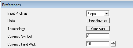
Units This is either Metric or Imperial
Terminology This is either English or American
The differences in terminology are
[Aust-English / American]
Sarking/Underlay
Battens/Purlins
Verandah/Porch
Cartage/Delivery
Downpipe/Downspout
Shell end/Hip starter
Apron/Skirt
Barge Rake/Verge, Rake
Colour/Color
Labour/Labor
Step/Roof-to-wall
It is fair to say that the terminology differences are notional only as regional differences also exist that make such a process flawed from the start.
Currency Symbol You can set this to any character or group of characters you want.
Currency Field Width This is the number of digits you want to be able to see in currency fields on the Reporting dialog boxes. If dealing in US or Australian dollars, the default is adequate. For Italian lire and Filipino peso, you may want to make it larger.
Number of Outlines to Save The number of job perimeter outlines saved to the file in date and time order, for later recovery under Const-Roof > Recover. Default is 20 but may be set to any number, say 100 or 150 for example.
Tiles Database to Use This is either Tiles or Tiles+. This selects the particular tile data file structure you wish to use for the Cover > Select-Tile command. They are not inter-changeable so be sure to read the respective descriptions in this manual to understand which one you should use.
Costing – Merge Same Product Code Items Y/N – sets whether you want items with the same product codes to be merged into one line item in the material list under Reporting > Supply Only or Supply and Install. This function searches the job Reporting data for products that may be used for different applications (such as screws) but are actually the same product and product code, and adds them all together as one line item on the quotation.
Import GRIM File on Start-Up Y/N – Allows you to turn on or off the Import GRIM file process when you open the software.
Allow Editing of Pricing Files Y/N – Allows the administrator to set a password on editing material or labour pricing files to make them tamper tolerant. A blank file called sysprefspwd.dat is shipped with the software. This does not make the files tamper-proof, but it will certainly slow down unskilled or unauthorized users.
By default, the setting is Yes allowing anyone to edit any pricing file. If the option is set to No pricing options in all materials and/or labour under Set-Up are not accessible to the operator – they appear ‘greyed out’ on the dialog.
Allow Multi-Language Y/N – This option allows the software to operated in any language. All functions and dialogs now refer to an external file for the appropriate prompt to be displayed. By translating the files, there are 90+ files, to the required language the prompts will be displayed in this language. At time of printing German and Spanish are available and French is in the pipeline. The files must be saved in the folder ….\AppliCad\<program>\Language.
Number of Segments to Break Arcs into The software will only generate roofing and cladding to lines, but if an arc is found, that arc may be divided into line segments so that the geometry for the roof or wall will still be constructed correctly. Effectively the number of segments sets the resolution of the arc.
Hide On-Screen Command Hints Y/N – Allow the display or hiding of on-screen tooltip hints (on by default).
Show Word/Excel Processing Shows each stage of the output being processed as the report is generated. Only applies when the report is being generated from a Word Template or Excel spreadsheet.
Excel – Columns to Process Limits to range of cells in Excel to process. Useful if the total matrix of cells is large.
Excel – Rows to Process Limits to range of cells in Excel to process. Useful if the total matrix of cells is large.
Leave Word/Excel Documents Open This leaves Word or Excel open with the generated report displayed. This is useful to make further edits or check the result before printing.
Show Zero Qty Line Items in Costing As it suggests, enables the option to display the zero quantity items in the costing report screen (Reporting > Supply Only or Reporting > Supply and Install). You would leave on so that you can modify the quantity to add an item. This may be used as a prompt for occasional use items such as fuel surcharges etc. Create a bunch of Extra Items with zero quantities and they become your check list.
Automatically Print Word/Excel Reports/Drawings Y/N – When set to Yes, the report is printed to the default Windows printer, as soon as Word or Excel completes creating the report from your template.
Use Commercial Mode Y/N This option enables the use of Substrates, Systems and Assembly Groups for specific large scale operators interfacing with very large material databases and assemblies. Not for general use. Leave set to No unless specifically requested by the AppliCad Support department to change. It requires all trim, accessory items and assembly groups to be defined BEFORE use. This includes telling each metal panel which assembly applies when Commercial Mode is enabled. You cannot do ‘half this’ and ‘half something else’.
Add Product Codes to Metal Panel Labour in GRIM Oot Y/N – allow the labour product codes to be output to the GRIM output file. We’ve provided this switch so as not to change the GRIM file format for those who have written programs to read in the file format (post V8.2).
Show Newer Job Info Dialog Y/N – allows the Job Info dialog to switch between the version with ‘WindZones’ and that with ‘Notes’ (see description of JobInfo) below.
Use Block-Cutting Dimension Dependencies Y/N
 This adds the button [Block Cutting Dimension Dependencies] to the functionality of Panel Labelling, by providing a dimension insertion option within Block-Cutting, as well as adding the block reference into the dimension. Note – the [Dimension Reference] function must be enabled in System Preferences for it to appear in the dialog and to use. Read about it in System Preferences so that you understand the purpose, before you turn it on.
Use Flashing Identifiers Y/N – The same applies to Flashing annotation, with the additional functionality that flashing labels can be grouped by just their length, or additionally by a line also. If set to this latter option individual lines, despite having the same flashing type and length, will still have a separate identifier so that they are more easily identified on the drawing, and where the material is to be installed on the roof, thus greatly assisting the installers position materials around the job.

See example below for a Soaker Flashing along a Step line.

Reverse Name/Desc for Insulation Y/N – The ability to swap the use of the Name and Description fields for Insulation/Underlay selection ensures the product “Description” aligns with the “Finish” of the estimated product when listed in the Supply & Install dialog.
File Directories These are the directory(s) or folders where the system will look for your data files. These are the data files containing material definitions, report templates and labour rate details (.csv, .dat and .bin and some .dab files). It may include the CAD (.dab) files you create for your jobs. If there is no directory path, then the system first looks in your ../User directory. If the file is not found there, it looks in the ../Programs directory.
You select a new folder or directory by clicking the ‘…’ button. Clicking the ‘x’ button will reset the folder or directory to nothing. If you wish to use a folder or directory on a file server so data files are accessible over a network, you will first need to map the network drive using Windows Explorer.
The option exists to define separate folder for the output of the GRIM file, thus eliminating the need to copy the file on completion of the report.
Setting User and Corporate data Folders

The directory/folder structure has been implemented to provide for more comprehensive data and job file management, especially at larger sites with many operators. If you are a single operator, keep it simple. The default settings for folder locations are as displayed – local drive, C:/AppliCad/Roof Wizard/User or D:/AppliCad/Roof Wizard/User. If you need to access any file such as an image file of a roof, a PDF or even a backup of a .dab (job) file, copy it to the ../User folder before you open the software.
It is expected that multiple users on a company network will save all their work and access data files from a common shared drive. This ensures that all users are accessing the same pricing data, jobs are available to everyone for checking or reporting and the system admin is backing up everyone’s work at once.
Corporate Folder – The software can be set to search the “Corporate Folder” prior to the “User Folder” when looking for databases, models, CSV files etc. This function will allow the user to copy a number of “Corporate Default Settings” to the Corporate folder and by setting this switch to [Yes], will ensure these options are found by the software before being located in the User folder. Thus, Corporate Standards for the software appearance, units, setup files etc will be able to be maintained more easily while still allowing specific job settings to be set by the user. To enable this, it is appropriate to set the option Reverse User/Corporate Folder Search [Y/N] in the Preferences as well. This provides considerable flexibility in how job files are saved for access by all networked users while allowing individual user settings to be maintained.
GRIM Folder – This is the path you set for exporting the GRIM text file to. This is set so that any other programs that you might interface the results of our software with, can find the GRIM data and picked up automatically.
Report Folder – You may also set the folder where you want your Excel or Word reports to be saved by default. This is so that you can keep those people checking reports (cutting lists, quotations etc.) away from the working folders (typically ..\User) and reduce the potential for unauthorised modifcations to the pricing and product specification settings. Note that the standard CAD reports will not be saved to this folder as they are typically sent directly to a PDF and saved as a part of the job model file as a model with the prefix REP- for a report or DWG- for a drawing.

Temporary Folder – This folder is typically a sub folder below the ..\User folder. It is where temporary files that are generated as part of the process of creating cutting lists and pricing are saved. These files are re-rcreatd each time a job is processed and are not required after the report is generated. It is good housekeeping to go into this folder on occasion and delete the entire contents of the ..\User\Temp folder so they do not ‘clog up’ the disk storage.
For a summary of file types and where they must be located for correct operation of the software refer to the File Types and descriptions at the end of this document. Set the path to folders according to your system set-up. If you are unsure, please refer to your System Administrator or IT expert, or call the AppliCad Support Team. If these are not set correctly all sorts of weird things can happen.
Note that when setting file paths and ‘start-in’ folders, this is not only setting to check. There are other settings to be checked as the software starts starts up and subsequently finds the initial program setup information such as version details, units etc. and this is described below.
Setting the Network File Sharing Location
The software is a single user license product – one license, one user. However, the software is network aware and allows you to save work on a shared network server drive so that printers, material definitions, settings and job files may be shared with other users. If you are not sure about this, engage your IT guy to help.
If you need to check and/or set the paths for the software to look in the correct location for its data – there are four locations where you need to check/set the file path. Setting up connections to a shared drive, such as Z:/AppliCadUser is described here.
Note: If you are not sharing files on a network, then the default location is C:/AppliCad/Roof Wizard/User. You can also use the steps described here to check that the software is pointing to this location instead of the example used. If you have navigated away from the ../User folder and opened a file, then the software remembers the new path and then will not be able to find all your system settings and pricing files etc. As explained above, if you need to access any file such as an image file of a roof, a PDF or even a backup of a .dab (job) file, copy it to the ../User folder before you open the software.
- Right column of System Preferences table…
Currency Precision (Reports Only) This allows you to set the number of decimal places you want your currency to appear on your reports only.
Tax Name This is the name of the taxation system in use in your country. (eg: GST, VAT, Sales tax). You will see this value displayed on the various Reporting dialogs and the reports where tax is required.
Tax Percentage This is the tax percentage you want to set.
Payment Terms for Job Details This is the payment term you want to appear on your reports.
Use File Locking (Networking) In larger firms where the estimating office has multiple operators doing estimates, file locking restricts the operator from opening a job already being worked on by one of their colleagues. This prevents inadvertently over-writing some else’s data-files. If the software has been closed in error and lock files have not been properly cleaned up, it may be necessary to delete them. This may be done with the button – Delete to delete existing lock Files – these are files in the …\User folder with a *.LOC extension.

To prevent other operators opening the same model database (a *.DAB file), you must also enable the CAD file locking. To do this go to CAD > DEFAULTS > System Settings > Setup from the pulldown menu and enable File Locking. Make sure that the lock file directory is also setup to point to a folder in the shared network, …\User folder.
In this example, Y:\Share where Y: is the shared network drive and the Share folder is the folder where the CAD lock files are created.
The CAD lock files have the database file name with a *.LCK extension.

Default Tiling Estimation Method (Area/Coursing) Presets the estimating method quantifying tiles, shingles, shakes and slate – the options are by Area or by Course. Area calculates quantity based on pieces or bundles per square and Coursing actually lays the pieces course by course on the roof model and then counts the pieces. (Waste, if defined, is applied later, during the cost reporting operation of Supply Only or Supply and Install).
Allow Plotting to PDF files Y/N – Allows the operator to print directly to PDF files. Requires a third party PDF generator such as Adobe Acrobat™ or PDF995™ to be installed (not supplied by AppliCad Software).
Job Wizard on Start-Up Y/N – If set to Yes, the Job Wizard guides the operator through the steps of creating and estimating a job. This is especially helpful to new operators and is usually turned off once the process is learned and understood.
Use Stage Manager Y/N – Turns on the stage manager function if you require the ability to break a quotation down into Stages – refer to Stage Manager elsewhere in this manual for more details of Stage Manager.
Copy Database Locally before Open Y/N – Added option to “Copy DABS Locally” which will result in database files being copied to the local machine before being read by the software. This switch can improve database read and write speeds across slow WAN and LAN networks.
Use Interval Labels for Labour Y/N – allows the output of labels set up under Set-Up > Metal/Tile Pay Rates Variable > Intervals to be displayed in the Labour dialog of the Costing > Supply&Install dialog and also to be output in the GRIM file exported – (Set-Up > Pay Rates > Metal/Tile Labour > Intervals)
Use Costing Plus Y/N – this function allows the software to use the Tiles+ tile structure and the Costing+ pricing structure to make comparisons with cost and sell price to determine profit margin.
Excel – Columns to Process Limits to range of cells in Excel to process. Useful if the total matrix of cells is large.
Excel – Rows to Process Limits to range of cells in Excel to process. Useful if the total matrix of cells is large.
Output of Material Cutting List Y/N – This allows you to change the output of your material cutting list, from Feet & Inches to Inches only.
Note that this is only applicable for those working in Imperial measurements. It is not displayed when in Metric units.
![]()
When set to [Inches Only], this changes the cutting list tables for Section Reports and the output to the various rollforming machine cutting list formats [Export to Rollformer] to inches.

Use Roof Area if no Panels Applied Y/N – If no panels have been appied to the roof model, the roof area will be used as the roof area quantity for material cost purposes (based on the cost per square (foot or metre) of the selected material item.
Show Print Dialog when Printing Y/N – If you have a single printer then typically you would set this to No and it will go directly to that printer. If you have a range of printing options as you might have on a network, then set to Yes and select the required printer to send the print job to.
Reverse User/Corporate Folder Search Y/N – Allow the software to search the “Corporate Folder” prior to the “User Folder” when looking for databases, models, CSV files etc. This function will allow the user to copy a number of “Corporate Default Settings” to the Corporate folder and by setting this switch to Yes, will ensure these options are found by the software before being located in the User folder. Thus, Corporate Standards will be able to be maintained more easily while still allowing other settings to be set by the user.
Treat Gutter/Valley Intersection as a Stop End Y/N – Allows you to modify the way in which “Stop End” accessories are calculated where an Eave, a Valley and a Raking Line come together. It effects the way accessories are calculated.
![]()

Update Panel/Tile Definitions during Costing Changes made to an estimate do not always flow through to the Supply & Install dialog, as we often found with metal panel changes and tile, shingle and shake selections. Sometimes this is deliberate (estimators comparing relative pricing for materials) but often it is unintentional and leaves the chance open for the incorrect product to be specified from what the estimator was intending. As such, this switch can be set to check these major component items such as metal panels and tile/shingle/shake systems that indicated by the prompt – [Panel/Tile Definitions have changed, do you want to Update dialog to software?]
GRIM Out Unique Fabrication Codes in Pricing Y/N – , the ability to output Custom Flashing product codes, as specified in the Multi-GRIM Quotation Output dialog, can now be enabled through the Supply & Install dialog also, allowing these product codes to flow through to the reporting. Specification of the file containing the Custom Product Codes then needs to be specified in the Quoting > Multi-GRIM Out > Multi-GRIM for Quotes dialog, with the file containing relevant Product Code structures for each manufacturer.

The ###GIRTH, ###BENDS and ###CODE sub-strings can be used to automate the creation of the new product code – as described in MultiGrim setup.

The resultant product code will then be constructed for each Custom Flashing and will appear in the Supply & Install dialog and flow through to the reporting, thus ensuring reporting and GRIM output results match.

Plane, Roof and Wall Line Options

Displays a dialog box to select what plane or line options you wish to set up.
Roof/Wall Plane Options
Selecting Plane Options brings up the following dialog box where the operator an set whether roof and wall planes are displayed as a filled area or as cross-hatched lines.
If Filled Planes is selected, the Filled Plane Intensity needs to be set, making the filled planes lighter or darker. We have found that a plane intensity of about 0.35 or 0.4 works well.

Any category of material can be set to any colour number. Any colour number can be any colour, set using the function CAD > Defaults > Colour Table (more information below). Remember that these colour numbers may be used for many entity types, so if you change colour 10 for this purpose, it might not be what you need where colour 10 is used elsewhere, for a line type for example.

Once set, select [Apply] and the new settings are applied to your job. These settings are saved with the job when you select [File > Save].
If Roof/Wall Plane Style is set to [Hatched], then you get extra options to set for the line style used for the hatch pattern: Style – whether it is a dashed, dotted or solid line; and Weight – the ‘thickness of the line when displayed on screen and plotted on the report page.
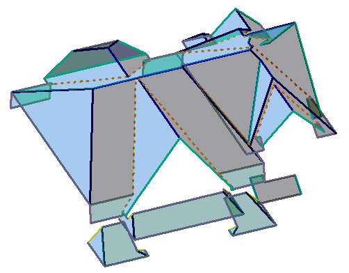
Roof model with Filled Planes
Once set, select [Apply] and the new settings are applied to your job and are then used on all subsequent jobs.
These settings are saved when you select Apply, [OK] and then [OK] again in the Preference Settings dialog. They are also saved with the job when you select [File > Save].
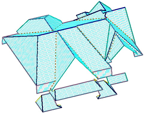
Roof model with Hatched Planes
Roof/Wall Line Options
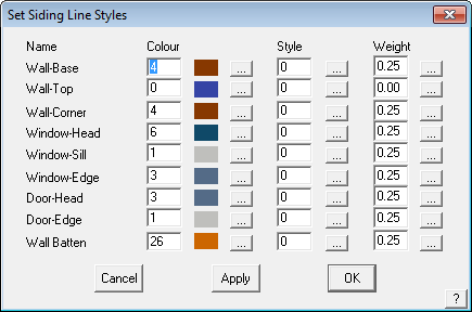
This command lets you set the colour, style and weight (line thickness) of the different line types in a roof and wall model.

When [Set Line Styles] is selected the roof line styles are displayed and may be changed to suit the personal preferences of the operator. The Line Function is the name Roof Wizard uses for a line, the Name is the term that the operator wants that line to be called. Once changed, that name is used throughout the program, where ever that Line Function is used. Obviously it is preferable that each line function has a unique name. Set line colours, styles a line weight to suit the needs of your office. If you have a dark background in the program’s workspace, then dark lines will be hard to see. Similarly, white lines are impossible to see on a white background. When selecting line colours, also consider the output reports. Most of us print onto white paper, so select line colours that will be legible when printed!
Extra User-Defined Line Styles The operator may define 4 additional line styles or categories for use on the roof model – USER1 to 4. Once the names are defined, they become visible throughout the Cover > Flashing type options and also for Tools > Change Line Type options.
When you select [Apply], the changes are made to the lines in the current model and the dialog box remains displayed. When you click [OK], the settings are saved and are used for lines inserted from that time on.
Regardless of what name is used, the line style function is as described in the second column. This is important to keep in mind when setting up flashing and trim options under the Set-Up > Flashing command.
When you click the colour setting button, the Defaults Colour dialog box is displayed.
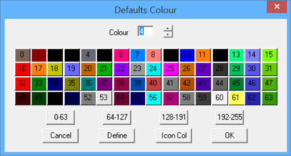
Here you click the colour number you want, and then click [OK]. You will then see the colour index transferred to the Set-Line-Styles dialog. This changes the colour number. A colour number may be any colour. The colour map for each colour number is defined using the Defaults Colour Table accessed by selecting the [Define] button.
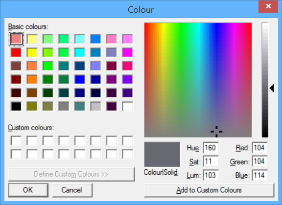
Select from the basic colours, or define a custom colour by using the Hue, Saturation, Luminosity scales or the Red, Green, Blue scales. Once selected, select [OK] and that will be the line colour used. Make allowance for the screen workspace background colour settings you use as well as how the selected colour will appear on a printed report and indeed, whether you are printing in colour or monochrome.
Line Style and Line Weight
Selecting the line style and line weight is similar in operation.
Below is the Defaults Style dialog box. Selecting a style number changes the line style for that line category. For example, valley lines are often selected to be a dashed line to highlight them against hip lines.
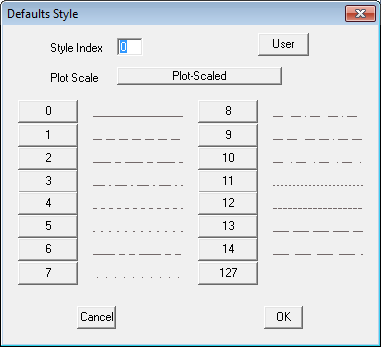
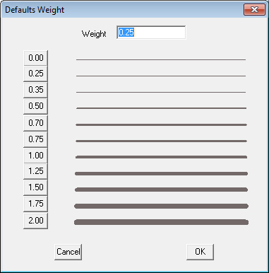
Below is the Defaults Weight dialog box.
The [Show Angle] option displays the angle of bend for the trim, which is the angle between adjacent roof planes. It becomes part of the information that describes the flashing/trim profile in the flashing cutting list, thus assisting the correct pfabrication of the part. When selected, the X appears in the cell.
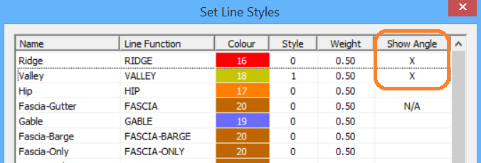
To set, simply double click the cell on the dialog and then the fabrication angle of bend will be displayed as part of the flashing report as shown below in the cutting list summary – similar to the list below.

When checked, the software will add the angle of bend to the annotation of the roof plan as well, thus allowing installers to install the correct trim to the correct edge. This is particularly useful on complex roof shapes with multiple roof pitches.

Note: The line annotation is only applied to the drawing when the trim is manufactured ‘cut to length’. If your trim is manufactured as stock length ‘sticks’ of say 10’3″ or similar, then the lines are not annotated as all the lengths are the same. If you have a range of bend angles, (caused by multiple roof pitches) then the lines will be annotated with the bend angle only.

Also note that you must set the estimation method to calculate each run separately – NOT total run. Refer description of setup for estimation methods below.
Notes regarding Single-Slope trim at the top edge.
In parts of Australia, they call the top edge of a single slope flat roof a ‘monoridge’. As you know we have a line type called Monoridge but be aware that this was something we developed 30 years ago specifically for Tile roofs. Flashing is not applied to this line type unless you create a User line called MonoRidge in the preferences. However, this is not the best option.

When set, it doesn’t do anything when applied to a metal roof. It is very specific to tiles in the current setup.
So, when you try to generate a flashing cutting list, nothing is identified for the Monoridge line types.

Turn on the [Show Angle] function for Gable line types; set the ‘monoridge’ line to ‘Gable’ on the model and the software takes care of business for you, generating the correct cutting list for each part of the roof including all components for the roof.
Remember, by default, the software creates an Apron line type at the top edge, assuming that the single slope roof is going to butt up to a wall.
Where it is free standing single slope roof, not joining anything, the ‘Gable’ linetype is the best option, definitely NOT Monoridge, unless it is a tile roof.

With this set, you get the following result, which is 100% satisfactory for our friends in Queensland (Australia) and other places where this is critical for the correct material to be fabricated and shipped to site. Both Barge cap, bent to the correct angle for each situation on this roof, and Fascia-as-Barge are calculated and listed separately in the cutting list.
When accessories are defined the correct accessories are also calculated.

Nice and tidy!

Dimension Default Settings
(Pulldown Menu Only)
After selecting Defaults, the Dimension defaults dialog is displayed.
Dimensions Defaults

![]()
Note: Typically, the font used to annotate roof planes and drawings is the font defined under CAD > Defaults > Text Defaults. As these may change from user to user, it is suggested that a text file called Fontfile.dat be created and saved in the User folder, thus ‘locking-in’ the required font style for each user. The font used on the roof plan for annotation such as area, azimuth etc will then be determined by the font defined in the Fontfile.dat. True type fonts will be listed by their name only (such Arial or Calibri) and the CAD fonts by the name and the extension (such as HELV.FON for Helvetica font or ISO.FON for CAD ISO font). If no font file exists (it must be created by the user) then the CAD text default settings will be used.
Dimension Sizing Options
These options allow you to alter the size of dimensions for the four different methods. You will see the effect on screen and on the printed drawings.
Coursing Dimension Specific Options
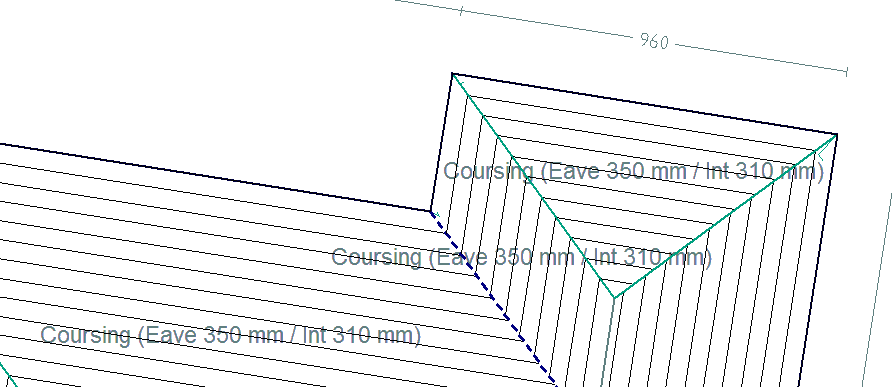
Set the height of the course dimension text and also the information to be displayed on the roof plan. For example – Coursing (Eave ###E mm / Int ###I mm) would insert Coursing (Eave 350mm / Int 310mm) on the drawing as shown below.
Ln-Ln Dimension Specific Options
Round Length Dimensions to .. sets the rounding up of the dimension number drawn on the roof drawing – in the example ±10mm.
Match Line Dimension Colour changes the dimension colour to be the same as that set for the line making it easier to associate a dimension with the matching line. If set to no, the default settings for dimension are used.
Dimension line Lengths Greater Than allows the operator to set how short the shortest lines to be dimensioned will be. Anything shorter than the specified length will not be dimensioned. This takes the clutter out of the drawing by not dimensioning lines that may not be important.
Dimension Distance Off Line sets the distance the dimension is to offset from the associated line – roof plan on the left is set to 0; roof plan on the right is set to 100mm.
![]()
Note: Be careful switching between metric and imperial units as this can have a detrimental effect on settings such as arrow size – 100mm in metric becomes a 100” in imperial.
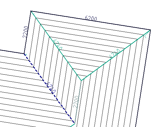
Without offest from the referenced line.
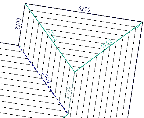
With offset from line set to required distance.
Azimuth/Area Dimension Specific Options
Round Area Dimensions to sets the rounding up of the area dimension number drawn on the roof drawing – in the example ±1sqm.
Azimuth Dimension Precision sets how many places after the decimal point.
Area Dimension Suffix adds a suffix to the area dimension such as SqFt or SqM. You may also use the ‘Alt’ and the numerics on the keypad to insert extended characters into the suffix – Alt+0176 for degrees symbol and Alt+0178 for the squared symbol.
Pitch Dimension Specific Options
Show Storey on Pitch Dimension adds the roof storey to the pitch dimension drawn on the roof plan. Used in conjunction with the precision, in this case one decimal place.
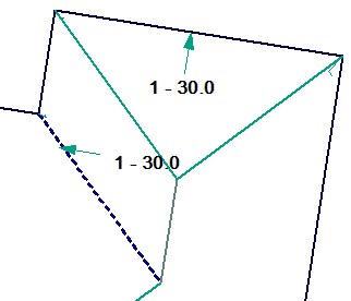
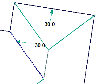
Pitch Dimension Precision sets how many places after the decimal point. Our example displays one decimal place.
Pitch Searator (Slope Only) sets the separator character btween the numbers indicating the slope of the roof. Typically a colon as shown, but may be a slash.
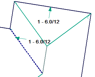
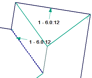
If you set the value to “None” (any combination or upper or lowercase letters that spells ‘none’) then the separator and the “12” value are left off the report. This often makes the report less cluttered and easier to read.


Show Slope Arrow Direction – Y/N Slope direction arrow may or may not be displayed.
Slope Direction Arrow Size sets the size of the arrow. Since we model the roof geometry at full size, the arrow would need to be about 1000mm as shown above (or the equivalent in feet and inches).
Default Dimension Colour – Allows you to quickly change the colour of dimensions with out backing out to the Dimension Default dialog box.
![]()
Note: Be careful switching between metric and imperial units as this can have a detrimental effect on settings such as arrow size – 1000mm arrow in metric becomes a 1000” arrow in imperial.
Set Report Options
This option provides the opportunity to pre-set the required reports that you would normally print, thus saving the time to select them for each job at the print stage.
Set Drawing Options
This option provides the opportunity to pre-set the required drawings that you would normally print, thus saving the time to select them for each job at the print stage.
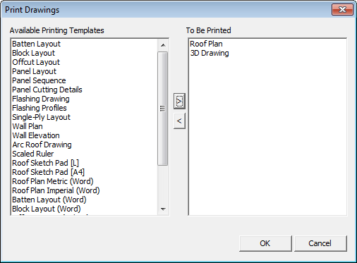
Table and List Defaults
Opens the dialog box where the text height for each standard report table or details text is set. The units are millimetres (do not use feet and inches).
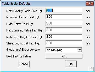
The option “Grouping of Sheet Lengths” refers to the creation of the sheet/panel cutting list and the options are No Grouping, Group by Length Alone or Group by Plane and Length.
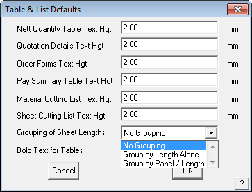
The Group by Length has the cutting list sorted by length. The Group by Plane and Length sorts them by plane then length, thus giving a list that relates to each roof plane.
The Bold Text for tables is self explanatory.
Keyboard Macros
This menu option starts the keyboard macro recording function, allowing you to ceate new keyboard commands for any key on the keyboard.
Upon selecting the ALT key or CTRL key from the keyboard, its currently assigned command statement is displayed in a dialog box. The selected key may then be re-assigned with a different command statement.
Main menu commands can be assigned to the selected key by beginning the command statement with !mainand then specifying the command and its modifier levels.

For example, the following command statement will enable File > Save the current database: !main save
The Inline Menu commands can be assigned to the selected key by beginning the command statement with !menu and then specifying (if required) the command and its modifier levels. For example, the following command statement will enable the Inline Window command, set all options to [Yes] and then await window definition:
!menu window out cross [OK].
 Tiles
Tiles
Here you can define a new tile in the database. After selecting define, the Define Tile dialog box is displayed. As is the case for defining all products in Roof Wizard, the key item in the definition is the Product Code – it is this that links the products with the accessories , the pricing and labour etc. The dialog box lets you enter textual information about the tile as well as geometric values. The textual information is used to select the tile later. The geometric values determine the course spacing and how many of these tiles are to be used for the job.
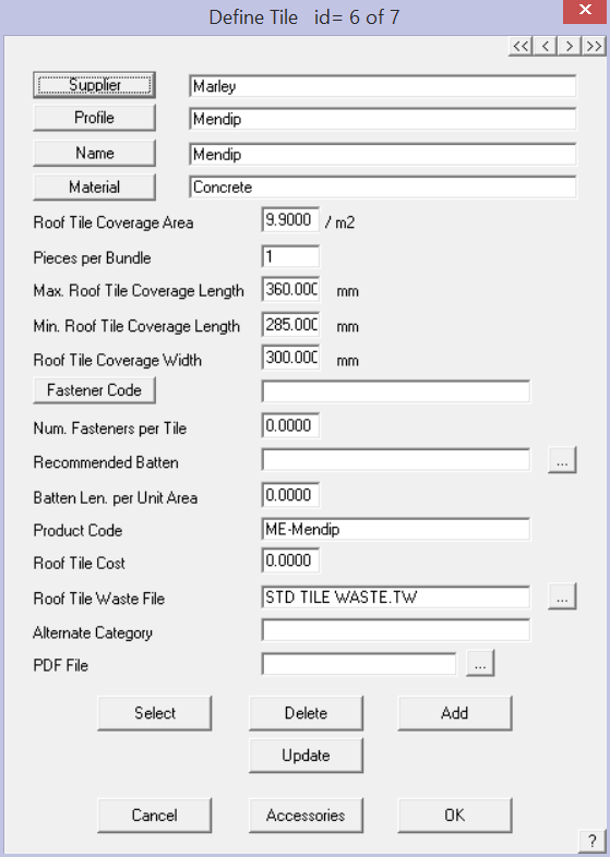
Supplier This is the supplier of the tile. You can enter any name you wish, or if you click the Supplier button, you can select the name from a list. The list is derived from all the supplier names already in the database.
Profile This is the profile of the tile. You can enter any name you wish, or if you click the Profile button, you can select the name from a list. The list is derived from all the profile names already in the database.
Name This is the name of the tile. You can enter any name you wish, or if you click the Name button, you can select the name from a list. The list is derived from all the names already in the database.
Material This is the material of the tile. You can enter any name you wish, or if you click the Material button, you can select the name from a list. The list is derived from all the material names already in the database. If the tile material is Concrete, then the concrete pay rates are used; if it is not concrete, then the terracotta pay rates are used.
Roof tile coverage area This is the number of tiles per square metre (or square foot depending upon units selected). This value is used if you choose to do the estimate by the area method.
Pieces per bundle This function may be used if your tiles are ordered/supplied in minimum quantities, such as per pallet or bundle. If this number is left at 1 (default) then the software quantifies per piece, however if you modify the bundle to a number greater than 1, the number of tiles will be reported in bundles/pallets instead of individual tiles. This might be used to order tiles by the full pallet (bundle).
Max roof tile coverage length This is the maximum length of coverage for this tile. This value is used later in the coursing commands to determine the course layout.
Min roof tile coverage length This is the minimum length of coverage for this tile. This value is used later in the coursing commands to determine the course layout.
Roof tile coverage width This is the coverage width of the tile. It is used to determine the number of tiles when you use the coursing method.
Fastener Code You may select a required fastener from the list of previousy defined fasteners. Select the button and all available fasteners will be displayed. You may also define a fastener or clip using the accessories option below.
Num. Fasteners per Tile Define the required fasteners per tile.
Recommended Batten Select the […] button to get a list of battens available for use with this tile.
Batten Len. per Unit Area Many installers use this formula to calculate the quantity of batten, especially when using the ‘Area Method’ of costing tiles.
Product Code Each different tile must have a unique product code. Typically the same code as used by the supplier so that the orders you generate have the same detail on them. The product code must be unique. The tile and all the tile accessories are associated by means of the product code.
Roof Tile Cost The cost per tile piece.
Roof Tile Waste File If you have defined specific tile waste factors for this profile, then this is where you link the tile to the tile waste file (refer Setup > Set Up Pay Rates > Tile Waste Factors).
Alternate Category Allows you to define a different category so that the tile may be listed under a different group in the Supply and Install summary list.
PDF File Allows you to define a PDF document that might include the tile spec sheet for example, for later inclusion in your document package.
Delete This button deletes the current definition.
Add This button adds the current definition to the database as long as it is unique.
Update This button appears only after you have selected Select. This button then updates the current record with the current details.
Select This button lists all the tiles in the database from which you can select one to view, edit or delete as required.
Cancel Does not make the changes permanent.
[OK] Makes all the changes permanent – nothing is actually written to the data file until you select [OK].
Roof Wizard is moving towards an improved pricing and job management solution, with linkages to external accounting systems, a requirement to allow splitting up of an estimate into various groupings became apparent. The best way to do this is with Quote Groups, and so the ability to modify the default “category” for each material item in the software has been provided for on each data entry dialog box.

In addition to this, the linking of a PDF file (typically used to describe the part) has been allowed for also so that documentation sets can be created for estimates without users having to go and search for the documentation relating to each part in an estimate at some stage when requested by their customer.
Both of these improvements have been added to all product definition dialog boxes and provide for hyperlinking to external product sheets etc.
A file is created called PDFS.CSV. This file contains the product code of the part, whether it be a flashing, metal panel, fastener etc. and then the name of the PDF file that needs to link to this. If a Drawing Report of type PDFReport is defined under Drawings, then it will allow a compile list of all PDFs to be sent to the printer.
Tile Accessories
Select the [Accessories] button to define tile accessories.
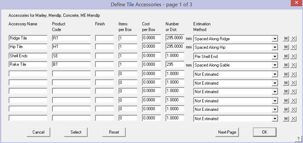
Ridge, hip and other tile accessories – These are defined as accessories to the field tile. You define the product name, product code and finish as appropriate. The product code is what is used to bind the accessory to the main product.
The product code must be unique to that part, although the part may be used for multiple tiles in which case it will have the same product code. The key to extracting the correct products in your material list is select the correct estimation method.
An accessory may also be a labour item, indicated by selecting the [M] button at the end of a row.
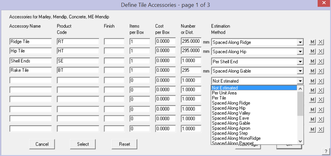
The correct association between the accessory and the tile is how the software gets your material orders perfect every time.
Not Estimated As it says, item is listed but not estimated.
Per Unit Area Item is quantified based on unit area of roof where this panel is installed.
Per Tile adds an accessory item(s) per tile
Spaced Along the Ridge Adds accessory item based on the ridge length.
Spaced Along the Hip Adds accessory item based on the hip length.
Spaced Along the Valley Adds accessory item based on the valley length.
Spaced Along the Gable Adds accessory item based on the gable length.
Spaced Along the Roof to Wall (Apron) Adds accessory item based on the apron length.
Spaced Along the SideWall (Step) Adds accessory item based on the sidewall (step) length.
Spaced Along the Monoridge Adds accessory item based on the monoridge length.
The software automatically adds an accessory category based on the flashing line types defined.
Per Apex Adds accessory item based on each ridge/hip apex.
Per Shell End Adds accessory item per hip end (a ‘shell-end’ piece).
Per Wind Zone Any additional accessories required due to the wind zone of the structure.
Select This button lists all the tile accssories in the database previously defined from which you can select one to add to the current accessories list.
Reset Aborts any current changes to the list.
[OK] Adds the accessories to the current tile record.
When you click [OK], you are informed that the changes you have made are saved. They are saved to a binary data file called – tiles_v6.csv. Users should be aware that this format of tile definition and database file is not the same as that used for Tiles+ as described below.
![]() Note: Be aware that there is another Tiles data structure we have called Tiles+. This structure is particularly suited to those markets where there are lots of accessory pieces such as half tile, verge tiles and special tiles etc. Review the description of Tiles+ before you decide which to use. In general, the Tiles database works in Australia and NZ, the Tiles+ database works in the UK and Europe, either method may suit the North American situation. The determining factor will be the number and style of cast or moulded accessory items used in the product system as additional accessory items. With the addition of Tile accessories to the Tiles database in Roof Wizard V8.0, the Tiles+ database has been made largely redundant.
Note: Be aware that there is another Tiles data structure we have called Tiles+. This structure is particularly suited to those markets where there are lots of accessory pieces such as half tile, verge tiles and special tiles etc. Review the description of Tiles+ before you decide which to use. In general, the Tiles database works in Australia and NZ, the Tiles+ database works in the UK and Europe, either method may suit the North American situation. The determining factor will be the number and style of cast or moulded accessory items used in the product system as additional accessory items. With the addition of Tile accessories to the Tiles database in Roof Wizard V8.0, the Tiles+ database has been made largely redundant.
Roof Wizard is moving towards an improved pricing and job management solution, with linkages to external accounting systems, a requirement to allow splitting up of an estimate into various groupings, became apparent. The best way to do this is with Quote Groups, and so the ability to modify the default “category” for each material item in the software has been provided for on each data entry dialog box.

In addition to this, the linking of a PDF file (typically used to describe the part) has been allowed for also so that documentation sets can be created for estimates without users having to go and search for the documentation relating to each part in an estimate at some stage when requested by their customer.
Both of these improvements have been added to all product definition dialog boxes and provide for hyperlinking to external product sheets etc.
A file is created called PDFS.CSV. This file contains the product code of the part, whether it be a flashing, metal panel, fastener etc. and then the name of the PDF file that needs to link to this. If a Drawing Report of type PDFReport is defined under Drawings, then it will allow a compiled list of all PDFs to be sent to the printer.
 Shingles
Here you can define a new shingle in the database. After selecting define, the Define Shingle dialog box is displayed. If you are in English (Imperial) units, you can set the coverage as per foot or per square.

Supplier This is the supplier of the shingle. You can enter any name you wish, or if you click the Supplier button, you can select the name from a list. The list is derived from all the supplier names already in the database.
Profile This is the profile of the shingle. You can enter any name you wish, or if you click the Profile button, you can select the name from a list. The list is derived from all the profile names already in the database.
Name This is the name of the shingle. You can enter any name you wish, or if you click the Name button, you can select the name from a list. The list is derived from all the names already in the database.
Material This is the material of the shingle. You can enter any name you wish, or if you click the Material button, you can select the name from a list. The list is derived from all the material names already in the database.
Product Code Each different shingle must have a unique product code. Typically the same code as used by the supplier so that the orders you generate have the same detail on them. The product code must be unique. The shingle and all the tile accessories are associated by means of the product code.
Shingle Coverage Area Options are – pieces per sq ft; pieces per square (100sqft); bundles per sq ft or bundles per square (100 sq ft).
Pieces per Bundle How individual pieces in a packaged bundle of shingles.
Cost The cost per piece/bundle.
Waste File If you have defined specific shingle waste factors for this profile, then this is where you link the shingle to the shingle waste file (refer Setup > Set Up Pay Rates > TILE Waste Factors).
Alternate Category Allows you to define a different category so that the shingle may be listed under a different group in the Supply and Install summary list.
PDF File Allows you to define a PDF document that might include the tile spec sheet for example, for later inclusion in your document package.
Delete This button deletes the current definition
Add This button adds the current definition to the database as long as it is unique
Update This button appears only after you have selected Select. This button then updates the current record with
the current details
Select This button lists all the shingles in the database from which you can select one to view, edit or delete as
required.
Cancel Does not make the changes permanent.
[OK] Makes all the changes permanent
The shingle definitions are saved into the binary data file, shingles_v6.csv and the accessories are saved to shingleaccess.csv.
Roof Wizard is moving towards an improved pricing and job management solution, with linkages to external accounting systems, a requirement to allow splitting up of an estimate into various groupings, became apparent. The best way to do this is with Quote Groups, and so the ability to modify the default “category” for each material item in the software has been provided for on each data entry dialog box.

In addition to this, the linking of a PDF file (typically used to describe the part) has been allowed for also so that documentation sets can be created for estimates without users having to go and search for the documentation relating to each part in an estimate at some stage when requested by their customer.
Both of these improvements have been added to all product definition dialog boxes and provide for hyperlinking to external product sheets etc.
A file is created called PDFS.CSV. This file contains the product code of the part, whether it be a flashing, metal panel, fastener etc. and then the name of the PDF file that needs to link to this. If a Drawing Report of type PDFReport is defined under Drawings, then it will allow a compile list of all PDFs to be sent to the printer.
 Shakes
Here you can define a new shake in the database. After selecting define, the Define Shake dialog box is displayed. If you are in English (Imperial) units, you can set the coverage as per foot or per square.

Supplier This is the supplier of the shake. You can enter any name you wish, or if you click the Supplier button, you can select the name from a list. The list is derived from all the supplier names already in the database.
Profile This is the profile of the shake. You can enter any name you wish, or if you click the Profile button, you can select the name from a list. The list is derived from all the profile names already in the database.
Name This is the name of the shingle. You can enter any name you wish, or if you click the Name button, you can select the name from a list. The list is derived from all the names already in the database.
Material This is the material of the shake. You can enter any name you wish, or if you click the Material button, you can select the name from a list. The list is derived from all the material names already in the database.
Product Code Each different shingle must have a unique product code. Typically the same code as used by the supplier so that the orders you generate have the same detail on them. The product code must be unique. The shake and all the shake accessories are associated by means of the product code.
Shingle Coverage Area Options are – pieces per sq ft; pieces per square (100sqft); bundles per sq ft or bundles per square (100 sq ft).
Pieces per Bundle How individual pieces in a packaged bundle of shakes.
Cost The cost per piece/bundle.
Waste File If you have defined specific shake waste factors for this profile, then this is where you link the shake to the shake waste file (refer Setup > Set Up Pay Rates > TILE Waste Factors).
Alternate Category Allows you to define a different category so that the shake may be listed under a different group in the Supply and Install summary list.
PDF File Allows you to define a PDF document that might include the tile spec sheet for example, for later inclusion in your document package.
Delete This button deletes the current definition
Add This button adds the current definition to the database as long as it is unique
Update This button appears only after you have selected Select. This button then updates the current record with
the current details
Select This button lists all the shakes in the database from which you can select one to view, edit or delete as
required.
Cancel Does not make the changes permanent.
[OK] Makes all the changes permanent
The shingle definitions are saved into the binary data file, shakes_v6.csv and the accessories are saved to shakeaccess.csv.
Roof Wizard is moving towards an improved pricing and job management solution, with linkages to external accounting systems, a requirement to allow splitting up of an estimate into various groupings, became apparent. The best way to do this is with Quote Groups, and so the ability to modify the default “category” for each material item in the software has been provided for on each data entry dialog box.

In addition to this, the linking of a PDF file (typically used to describe the part) has been allowed for also so that documentation sets can be created for estimates without users having to go and search for the documentation relating to each part in an estimate at some stage when requested by their customer.
Both of these improvements have been added to all product definition dialog boxes and provide for hyperlinking to external product sheets etc.
A file is created called PDFS.CSV. This file contains the product code of the part, whether it be a flashing, metal panel, fastener etc. and then the name of the PDF file that needs to link to this. If a Drawing Report of type PDFReport is defined under Drawings, then it will allow a compile list of all PDFs to be sent to the printer.
 Metal Panels
This is where you define the metal panels or sheets you use of the roof. It will also include polycarbonate or fibreglass sheeting, as they are selected from the same database for a similar purpose. As is the case for defining all products in Roof Wizard, the key item in the definition is the Product Code – it is this that links the products with the accessories , the pricing and labour etc.
When you select Set-Up > Metal Panels, the Define Panels dialog box is displayed similar to this:

Supplier This button lists all the suppliers in the sheeting database from which you can select one. You can also enter a new supplier’s name directly into the supplier field.
Profile This button lists all the profiles in the sheeting database from which you can select one. You can also enter a new profile directly into the profile field.
Note: if you wish to use the panel definition for a curved sheeting material (bullnose veranda’s and cranked eaves), then you must put a profile description that contains the word ‘curve’ or ‘curved’ in this box for it to be available eg. “Curve Quality Longspan” or “Curved Softform”.
Finish This button lists all the finishes in the sheeting database from which you can select one. You can also enter a new finish directly into the finish field.
![]() Note: If you insert ‘Painted’ or ‘Color’ or ‘Colour’ in the Finish box (indeed anything with ‘COL’ in the name such as colorbond or colorclip), then you will be prompted for a colour when it is selected for use. You define the colours available under Set-Up > Metal Colours.
Note: If you insert ‘Painted’ or ‘Color’ or ‘Colour’ in the Finish box (indeed anything with ‘COL’ in the name such as colorbond or colorclip), then you will be prompted for a colour when it is selected for use. You define the colours available under Set-Up > Metal Colours.
Fastener code This button lists all the fasteners in the fastener database from which you can select one. You can also enter a new fastener directly into the fastener field.
Product code Here you can enter a product code for ordering purposes. You must have a product code for each product as it is the product code that keeps it all together. Avoid using any special characters (@#$%&*!) and spaces. If you need a space, use an underscore eg Product_code.
Coil Info. Allows you to define details of the coil required for a job to facilitate ordering and pricing.

Fasteners This is either the number of fasteners per square metre (or square foot) or the number of fasteners per metre of purlin (or per foot of purlin) supporting this metal panel. For the latter, you must select and insert purlins from the Cover > Flashing dialog.
Coverage width The exposure or coverage width of the sheet. It is this number that determines how many sheets will cover the roof.
Thickness The base metal thickness of the sheet – used for information only.
Cost The cost of the material. The Reporting unit is defined by the button to the right of the cost field. This toggles between per unit area (either square metres or square feet) and length (metres or feet). If you set the unit to be area, then under the Reporting > Supply command, the area of material is reported. If you set the unit to length, then the length of material is reported.
Min order length The minimum length you can order. Set it to zero and you can have sheets down to the smallest length. It would be usual to set this to the sheet width.
Max order length The maximum length you can order. Set this to zero and you can get any length sheet – this would only be appropriate if you were roll-forming onsite.
Allowances to Use When the operator defines a set of allowances to be applied to the roof sheet/panel in calculating the coverage and quantity, an option exists to save that allowance set away for re-use with various sheets/panels. (Estimate > Allowances) This is where you elect the required allowance file to used and saves having to redefine it each time. The complete allowance set is only used by the Generate Panel Layout option. Other Estimate options only use parts of the allowance table. Refer to the specific command description for more detail.
Pay Rate Schedule allows the operator to pre-specify a labour rate to be used for a given metal panel. When a metal panel is selected under Cover > Select Metal, the pay rate schedule will be automatically selected by the software to whatever value is set within the selected metal panel’s definition. Options of Default and None are provided for the purpose of allowing the user to select the pay rate schedule at the time of panel selection per job (as per previous functionality) or no pay rate schedule to be used at all.
Is this a composite panel? When you split the panel later on (Estimate > Split-Panels) composite panels will report a cut back length and a lay direction too. Standard panels will not report these values.
Select This button lists all the sheets in the database from which you select to view, edit (to update or create a similar sheet) or delete.
Delete This button deletes the current definition.
Add This button adds the current definition to the database as long as it has a unique product code and description.
Roof Wizard is moving towards an improved pricing and job management solution, with linkages to external accounting systems, a requirement to allow splitting up of an estimate into various groupings, became apparent. The best way to do this is with Quote Groups, and so the ability to modify the default “category” for each material item in the software has been provided for on each data entry dialog box.
In addition to this, the linking of a PDF file (typically used to describe the part) has been allowed for also so that documentation sets can be created for estimates without users having to go and search for the documentation relating to each part in an estimate at some stage when requested by their customer. Both of these improvements have been added to all product definition dialog boxes.
Panel Accessories
Set up all accessory items required for the installation of your roof panels.

For each accessory, you enter the following information:
Accessory name This is the name by which you know this accessory (eg panel clip, joining plate).
Product code This is the code by which you know this accessory.
Finish This is the finish for the accessory. By default, the finish is that of the host flashing, but you can change it to what you want. If you define the finish as either “Colour”, “Color” or “Painted”, then the accessory will adopt the same colour as the host flashing.
Items per box This is the number of items of this type in a box you order.
Cost per box This is the cost of a box of these items.
Number This is a number (or a spacing) applied to the estimation method you select.
Estimation method This is the method by which this accessory will be estimated. (See below).
Number of fasteners This is the number of fasteners used to fix the accessory to the frame.
[M]/[L] This sets the Accessory item as a material accessory or a labour accessory to the trim item being defined. For example, a gutter or fascia may require special finishing that incurs extra cost over regular gutters. Add the charge to this list as a Labour item and it will be added to the labour summary.
[X] Deletes the Accessory item from this list.
Select The Select button lists all the accessories you have defined for all flashing, from which you can select one. Keep in mind that the supplier of an accessory is assumed to be the same as the flashing, except when you select an accessory from this list. In other words, by selecting an accessory from this list, you override the supplier’s name of the accessory.
Reset Resets the full list to the condition prior to changes.
[Cancel] Does not make any changes.
[OK] Saves all the changes to the data file, Sheeting.csv in the ..\User folder.
Panel Accessory Estimation Methods
The estimation method you select is one of the following:
Not estimated This accessory will still be reported in the material list in the costing, but will have zero quantity.
Per Unit Area Adds accessories simply based on a number per square of panel material.
Spacing along Panel (nett) This accessory is estimated as a function of the nett length of the panel. The nett length is the length this panel covers rather than the length of panel to order. The number then relates to a spacing along the panel (in mm or linear feet). You would use this method for things such as panel clips or brackets which hold the panel. If you set the spacing to be zero (0), the spacing will adopt the value you set under Roof-Defaults Rafter-Spacing. Therefore, if you have brackets dependent on the rafter spacing (which may differ from job to job), then use a spacing of 0.
Per Join This accessory is estimated as a function of the number of joins between connected panels. You might use this method to define specific joining sealant used to connect 2 pieces together.
Per Panel This accessory is estimated as a function of the number of pieces you are ordering for this flashing.
Per Inetersection with Batten/Purlin This accessory is estimated as a function of the number of times a panel crosses a batten or purlin line.
Per m in Zone This option allows you to set the additional clips and screws that would be required based on the wind zones defined on the roof (set under Cover > Zones).
Stock-Lengths Allows the operator to setup a table of stock lengths and costs. Typically used for long run pressed metal tile profile.

Once set, the overlap/underlap allowances set with Estimate > Gen-Panels > Modify-Panels > Split-panels will be applied to each panel when panel length is calculated. You must also set the panel allowances for this panel so that each panel is rounded up by the specified amount, then he panel nearest that length is selected. So when stock lengths are defined, you must also set up an appropriate allowance file for that panel.
Defining Panel Stock Lengths
For example, if you have a panel with stock lengths from 8′ to 20′ in 2′ increments, then you will define a stock length table for that panel eg Delpro16 as shown below:


Then you must create an Allowance table specifically for this profile so that each panel in the model is rounded up to 2′ or 24″ so that a panel can be found from the options in the length table.

And remember to specify the Allowance file to use for this panel only.

More details can be found in the description of use of Stock Lengths under Cover > Estimate Panels.
Material data files such as Metal Panels are best edited from within AppliCad software via the appropriate dialog box, however as they are in a comma separated text file format (CSV) they may also be edited in a spreadsheet program such as Microsoft Excel or a simple text editor.
Roof Wizard is moving towards an improved pricing and job management solution, with linkages to external accounting systems, a requirement to allow splitting up of an estimate into various groupings became apparent. The best way to do this is with Quote Groups, and so the ability to modify the default “category” for each material item in the software has been provided for on each data entry dialog box.

In addition to this, the linking of a PDF file (typically used to describe the part) has been allowed for also so that documentation sets can be created for estimates without users having to go and search for the documentation relating to each part in an estimate at some stage when requested by their customer.
Both of these improvements have been added to all product definition dialog boxes and provide for hyperlinking to external product sheets etc.
A file is created called PDFS.CSV. This file contains the product code of the part, whether it be a flashing, metal panel, fastener etc. and then the name of the PDF file that needs to link to this. If a Drawing Report of type PDFReport is defined under Drawings, then it will allow a compile list of all PDFs to be sent to the printer.
Metal Panels and Assembly Groups
When you have Commercial Mode enabled in System Preferences, the definition of your metal panel includes the ability to define an Assembly Group. Assembly Groups are defined in detail below.

Notice the additional line added to the Metal Panel definition dialog where the panel is associated with an Assembly Group previously defined. This function provides the ability to define various trim details for different installation situations where this panel may be used. For example, when used on a plywood deck or when used on an open frame structure.
Refer to the Assembly Groups set up below for details.
 Flashings
After you select [Set-Up > Flashings], the Define-Flashing dialog box is displayed.
![]() Important Note on setting up flashings and trim – From version 5.8 onwards an extra variable has been added (gauge) which makes the file not backward compatible with previous versions. The text file Flashing.csv describes all trim prior to V5.8 and if it exists will be read into the program. All new trim defined in V5.8 is saved to a file called Flashing_V6.csv. If a Flashing.csv file is read into v5.8 onwards it will be automatically saved as the new file format thus preserving the functions of previous versions.
Important Note on setting up flashings and trim – From version 5.8 onwards an extra variable has been added (gauge) which makes the file not backward compatible with previous versions. The text file Flashing.csv describes all trim prior to V5.8 and if it exists will be read into the program. All new trim defined in V5.8 is saved to a file called Flashing_V6.csv. If a Flashing.csv file is read into v5.8 onwards it will be automatically saved as the new file format thus preserving the functions of previous versions.
They are not backwards compatible.

As is the case for defining all products in Roof Wizard, the key item in the definition is the Product Code – it is this that links the products with the accessories , the pricing and labour etc.
Type of flashing This is a drop down list letting you select the category of flashing – one of Ridge, Valley, Fascia, Gutter, Barge, Apron, Batten, Box gutter, User-defined or Step.
Supplier This button lists all the suppliers in the flashings database from which you can select. You can also enter a new supplier’s name directly into the supplier field.
Finish This button lists all the finishes in the flashings database from which you can select. You can also enter a new finish directly into the finish field. If you insert Painted or Colour or Colour, the software will prompt for a paint colour when you use the material. You define the colours available under Set-Up > Metal Colours.
Fastener code This button lists all the fasteners in the fastener database from which you can select for use with this flashing. You can also enter a new fastener directly into the fastener field.
Description A user defined description of this flashing from which you identify this flashing.
Product code Here you can enter a product code for ordering purposes.
Fasteners per m The number of fasteners per metre (or per foot) for estimation purposes.
Minimum Length Sets the minimum length for any flashing when ordered. If a value other than 0 is specified, no flashings will be calculated shorter than the specified length. For instance, if a [Minimum Length] value of a given flashing is set to 600.0mm, any flashing that is calculated by the software as less than this length will be modified to be the [Minimum Length] specified, thus 600.0mm as per the example provided here. The new value calculated will appear in all labelling of the flashing on-screen, as well as in any reports that are output by the user. This option is not available for imperial units yet. In the case of imperial units, this option will not appear in the dialog as displayed above.
Maximum length The maximum length of this flashing you can order (or 0 if there is no maximum, that is, the flashing is cut to length). Refer to the description below regarding Estimation Methods as this effects the setting for lengths.
Gauge Displays the base metal thickness of the selected trim material.
Cost method This is either per metre (or per foot) or per length.
Cost per unit This is the cost per unit based on the above setting.
Estimation method This is the manner by which Roof Wizard estimates the number of lengths of this flashing. (See below)
Pay Rate Schedule You can nominate a specific pay rate schedule for this flashing. You can select it as:
None Do not calculate a labour charge for this item.
Default Use the default method (eg a ridge flashing will use the ridge labour item).
Current Use a designated line item in the currently selected pay schedule,
or
Select from a previously defined pay rate, which will be displayed as a list of optional pay rates from both the metal pay and the tile pay, in case they are different, and they usually will be.
First define the rates and save (described above).

So that you have the rate when you need it here…

Pay rate line item Use the designated User defined line item in the specified pay schedule defined under
Set-Up > Set Up Pay Rate > Metal pay rates – variable or Set-Up > Set Up Pay Rate > Metal pay rates fixed — Add-User This provides for special rates for special install processes that vary from standard for this flashing item such as scribing or caulking for example.
The link between the specified flashing and the special pay rate is saved to a file called FLPayLink.dat.

If no special pay rate line item is defined, the cell is blank and the standard rate is used.
Select This allows you to select an existing flashing from a list.
Delete This allows you to delete the current flashing.
Add This allows you to add a new flashing definition as long as it is unique.
Accessories This allows you to associate accessories to the current flashing. (See below).
Stock-Lengths This allows you to associate a list of stock lengths and costs to the current flashing. (See below).
[Cancel] This button cancels all changes you have made.
[OK] This button saves the changes you have made..
To assist in finding the required flashing during setup, the flashings may be sorted and filtered using the Search option or by Type etc reducing a very long list to a short list.
Roof Wizard is moving towards an improved pricing and job management solution, with linkages to external accounting systems, a requirement to allow splitting up of an estimate into various groupings became apparent. The best way to do this is with Quote Groups, and so the ability to modify the default “category” for each material item in the software has been provided for on each data entry dialog box.

In addition to this, the linking of a PDF file (typically used to describe the part) has been allowed for also so that documentation sets can be created for estimates without users having to go and search for the documentation relating to each part in an estimate at some stage when requested by their customer.
Both of these improvements have been added to all product definition dialog boxes and provide for hyperlinking to external product sheets etc.
A file is created called PDFS.CSV. This file contains the product code of the part, whether it be a flashing, metal panel, fastener etc. and then the name of the PDF file that needs to link to this. If a Drawing Report of type PDFReport is defined under Drawings, then it will allow a compile list of all PDFs to be sent to the printer.
The [Show Angle] option in Preference settings (described above) displays the angle of bend for the trim, which is the angle between adjacent roof planes. It becomes part of the information that describes the flashing/trim profile in the flashing cutting list, thus assisting the correct pfabrication of the part. When selected, the ‘X’ appears in the cell.

To set, simply double click the cell on the dialog and then the fabrication angle of bend will be displayed as part of the flashing report as shown below in the cutting list summary – similar to the list below.

When checked, the software will add the angle of bend to the annotation of the roof plan as well, thus allowing installers to install the correct trim to the correct edge. This is particularly useful on complex roof shapes with multiple roof pitches.

Note: The line annotation is only applied to the drawing when the trim is manufactured ‘cut to length’ or fixed length per run. If your trim is manufactured as stock length ‘sticks’ of say 10’3″ or similar, and you set the estimation method to be combine lengths for the total job, then the lines are not annotated as all the lengths are the same. If you have a range of bend angles, (caused by multiple roof pitches) then the lines will be annotated, provided you set the estimation method to calculate each run separately – NOT ‘total run’. Refer description of setup for estimation methods above.

This ensures that the correct trim is installed on the correct part of the roof.
Fall Protection
The fall protection option allows custom application of fall barriers to the perimeter of the roof or indeed any other lines. Fall Protection is a sub-set of the Flashings definition process and must first be defined with the Set-Up > Flashing command, with the Finish set to “Fall Protection”, something like this…

The fall protection is typically defined and quantified as a linear item that is, cost per metre or per foot. That is why it is defined under flashings.
Fall protection options allow for fall protection “systems”. The inclusion of ###Fall1Name, ###Fall2Name and ###Fall3Name, along with the ###Fall1Qty, ###Fall2Qty and ###Fall3Qty and ###Fall1Cost, ###Fall2Cost and ###Fall3Cost now allow estimators to produce exacting output of what is being estimated and calculated on various reports. In addition, the matching of this to modified categories ensures all results output.
Editing the Flashing_V6.CSV File
If you are defining flashing options and pricing directly via Excel and the CSV file Flashing_V6.csv, you will be asked to define the flashing type. This is defined according to the following:
0: Custom Flashings
1: Ridge Flashings
2: Valley Flashings
3: Fascia Flashings
4: Gutter Flashings
5: Gable Flashings
6: Apron Flashings
7: Batten Flashings
8: Box-Gutter Flashings
9: User Len Flashings
10: Fascia/Barge Flashings
11: Step Flashings
12: External Wall Corner Flashings
13: Internal Wall Corner Flashings
14: Window Sill Flashings
15: Window Edge Flashings
16: Window Head Flashings
17: Door Edge Flashings
18: Door Head Flashings
19: Hip Flashings
20: Wall Top Flashings
21: Wall Bottom Flashings
22: User1 Flashings
23: User2 Flashings
24: User3 Flashings
25: User4 Flashings
26: Wall Batten Flashings
27: Roof Flashings
28: Wall Flashings
29: Door Flashings
30: Window Flashings
31: Window/Door Flashings
32: Roof/Wall Flashings
Flashing Estimation Methods
The estimation method is one of:
 Split each run up to the maximum length – this method measures each run and divides it into a number of equal length pieces which do not exceed the maximum length. Run and Lap allowances are also taken into account.
Split each run into maximum length pieces – this method measures each run, then supplies enough maximum length pieces to cover the run. Run and Lap allowances are also taken into account.
Split total run length into maximum length pieces – this method adds all runs of this flashing, then supplies enough maximum length pieces to cover the entire length. Run and Lap allowances are taken into account.
Split each run into stock length pieces – this method measures each run, then looks at the stock lengths you have defined for this flashing. It then supplies a combination of stock length pieces to cover this run taking run and lap allowances into account.
Split total run length into stock length pieces – this method adds all the runs of this flashing, then looks at the stock lengths you have defined for this flashing. It then supplies a combination of stock length pieces to cover this run taking run and lap allowances into account.
When you select [OK] after defining a new part the information is saved to a file called Flashing_V6.csv in the ..\User folder. If you have changed any information, select [Update], then [OK] to save the new information.
Flashing Accessories
When you click the Accessories button, the following dialog box is displayed.
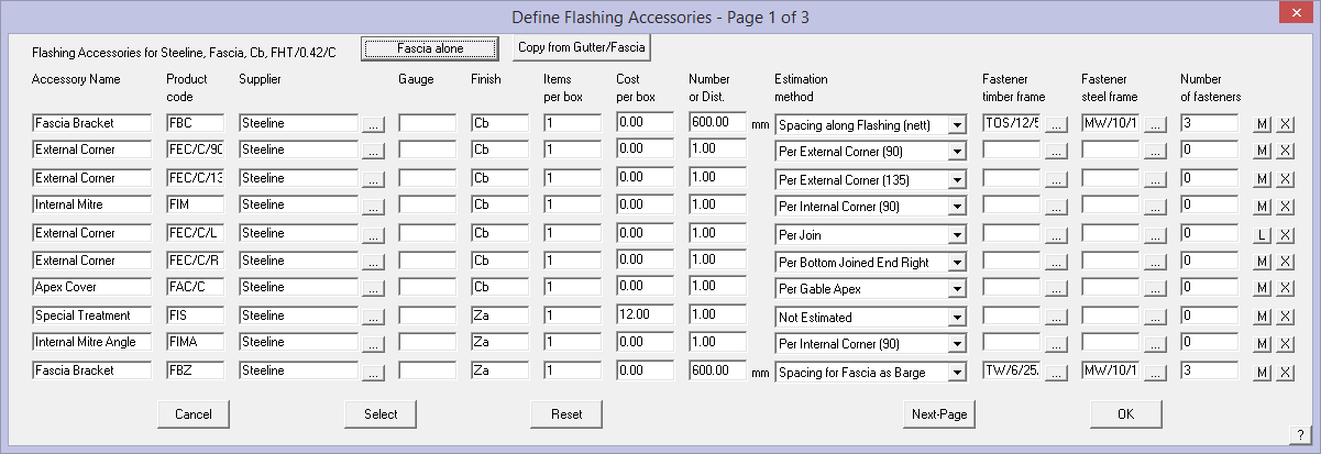
This is the first page of 3 pages of accessories you can define for this flashing. On each page there is space for 10 accessories to be defined. Note the Labour accessory item designation [L], material accessory item desgination [M].
![]()
Note: You may also copy the accessory items for a fascia from a corresponding Gutter Only or Fascia/Gutter item previously defined. This saves a lot of time when setting up the flashing database. The same applies for Gutter definitions. There is a limit of 2000 accessory line items total in the access2.csv file for all flashings.
For each accessory, you enter the following information:
Accessory name This is the name by which you know this accessory (eg Gutter clip, joining plate).
Product code This is the code by which you know this accessory.
Supplier Accessory supplier’s name – might not be the same as the flashing supplier.
Gauge Gauge of accessory material.
Finish This is the finish for the accessory. By default, the finish is that of the host flashing, but you can change it to what you want. If you define the finish as either “Colour”, “Color” or “Painted”, then the accessory will adopt the same colour as the host flashing.
Items per box This is the number of items of this type in a box you order.
Cost per box This is the cost of a box of these items.
Number This is a number (or a spacing) applied to the estimation method you select.
Estimation method This is the method by which this accessory will be estimated. (See below).
Fastener timber frame This is the fastener used to fix this accessory to the frame of the structure. This is the fastener used if the frame has been defined as Timber under Job-Info > Job-Details. You can either type the code into the field directly, or click the ‘…’ button to list the available fasteners.
Fastener steel frame This is the fastener used to fix this accessory to the frame of the structure. This is the fastener used if the frame has been defined as Steel under Job-Info > Job-Details. You can either type the code into the field directly, or click the ‘…’ button to list the available fasteners.
Number of fasteners This is the number of fasteners used to fix the accessory to the frame.
[M]/[L] This sets the Accessory item as a material accessory or a labour accessory to the trim item being defined. For example, a gutter or fascia may require special finishing that incurs extra cost over regular gutters. Add the charge to this list as a Labour item and it will be added to the labour summary.
[X] Deletes the Accessory item from this list.
Select The Select button lists all the accessories you have defined for all flashing, from which you can select one. Keep in mind that the supplier of an accessory is assumed to be the same as the flashing, except when you select an accessory from this list. In other words, by selecting an accessory from this list, you override the supplier’s name of the accessory.
For fascia flashings, you will see a button labelled [Fascia Alone]. When clicked, this button toggles between [Fascia Alone] and [Fascia with Gutter]. This setting allows you define a set of accessories for a fascia and a fascia-gutter combination independent of each other.
If the setting is [Fascia Alone], then these accessories are quantified whenever this fascia is used. If the setting is [Fascia with Gutter], then these accessories are only quantified when the fascia is used with a gutter. (A line adopting a fascia-gutter combination is tagged as FASCIA). If you have no accessories defined for the “Fascia with gutter” case, then the accessories used for [Fascia Alone] are quantified.
For gutter flashings, a similar feature is available. The button in this case toggles between “Gutter alone” and “Gutter with fascia”. Similarly, you can define a set of accessories for when the gutter is used individually (perhaps it is attached to a timber fascia) and when it is used in combination with a fascia
Flashing Accessory Estimation Methods
The estimation method you select is one of the following.
The number in square brackets [n] is the number used in column 11 of the saved accessory definition file Access2.csv that defines the estimation method for each accessory item.
Not estimated [0] This accessory will still be reported in the material list in the costing, but will have zero quantity.
Spacing along flashing (nett) [1] This accessory is estimated as a function of the nett length of the flashing. The nett length is the length this flashing covers rather than the length of flashing to order. The number then relates to a spacing along the flashing (in mm or linear feet). You would use this method for things such as gutter brackets which hold the flashing. If you set the spacing to be zero, the spacing will adopt the value you set under Roof-Defaults Rafter-Spacing. Therefore, if you have brackets dependent on the rafter spacing (which may differ from job to job), then use a spacing of zero (0).
–
Per internal corner (90) [2] This accessory is estimated as a function of the number of 90 degree internal corners connecting 2 runs used by this flashing.
Per external corner (90) [3] This accessory is estimated as a function of the number of 90 degree external corners connecting 2 runs used by this flashing.
Per internal corner (135) [4] This accessory is estimated as a function of the number of 135 degree internal corners connecting 2 runs used by this flashing.
Per external corner (135) [5] This accessory is estimated as a function of the number of 135 degree external corners connecting 2 runs used by this flashing.
Per internal corner (other) [6] This accessory is estimated as a function of the number of non-regular internal corners connecting 2 runs used by this flashing.
Per external corner (other) [7] This accessory is estimated as a function of the number of non-regular external corners connecting 2 runs used by this flashing.
–
Per free left hand end [8] This accessory is estimated as a function of the number of free ends of this flashing. Left hand relates to looking at the run from the outside of the structure. You would use this method to define left hand stop ends/end caps for gutters.
Per free right hand end [9] This accessory is estimated as a function of the number of free ends of this flashing. Right hand relates to looking at the run from the outside of the structure. You would use this method to define right hand stop ends/end caps for gutters.
–
Per join [10] This accessory is estimated as a function of the number of joins between connected flashings. You would use this method to define specific joining plates (splice plates) used to connect 2 pieces together.
Per Gable Apex [11] This accessory is estimated as a function of the number of apex bends between 2 connected flashings. You would use this method to define apex pieces for the top of barge (rake) flashings on gable ends.
Per run [12] This accessory is estimated as a function of the number of runs covered by this flashing. In the case of gutter clips, you may want to space them evenly along a fascia but require one more for each run. You would then estimate the gutter clip, with the spacing method above as well as this method.
Per piece [13] This accessory is estimated as a function of the number of pieces you are ordering for this flashing.
Fastener for timber frame [14] This accessory is estimated as a fastener for a timber frame structure based on the total length of runs covered by this flashing. You would use this method to provide fasteners for the accessories in preference to specifying fasteners for each accessory (if they are the same).
Fastener for steel frame [15] This accessory is estimated as a fastener for a steel frame structure based on the total length of runs covered by this flashing. You would use this method to provide fasteners for the accessories in preference to specifying fasteners for each accessory (if they are the same).
–
per bottom joined end left [16] This is at the bottom of a rake line, connected to the same flashing type.
per bottom joined end right [17] This is at the bottom of a rake line, connected to the same flashing type.
per bottom free end left [18] This is at the bottom of a rake line, not connected to the same flashing. You would use it to distinguish between joined end positions.
per bottom free end right [19] This is at the bottom of a rake line, not connected to the same flashing.
–
per top joined end internal [20] This is at the top of a rake line, connected to the same flashing as an internal corner.
per top joined end external [21] This is at the top of a rake line, connected to the same flashing as an external corner.
per top free end left [22] This is at the top of a rake line, not connected to the same flashing. You would use it to distinguish between joined end positions.
per top free end right [23] This is at the top of a rake line, not connected to the same flashing.
–
spacing for fascia as barge [24] spacing of accessories along a fascia when used as a barge. This is a special method for fascia flashings used on barge (rake) ends. You can either enter a spacing value or enter 0. If you enter zero (0), then the rafter spacing you specified for the job is used.
–
per bottom joined left internal [25] This is at the bottom of a rake line, connected to the same flashing. You would use it to quantify barge moulds which cover the fascia at the eave/gable intersection as an internal corner.
per bottom joined left external [26] This is at the bottom of a rake line, connected to the same flashing. You would use it to quantify barge moulds which cover the fascia at the eave/gable intersection as an external corner.
per bottom joined right internal [27] This is at the bottom of a rake line, connected to the same flashing. You would use it to quantify barge moulds which cover the fascia at the eave/gable intersection as an internal corner.
per bottom joined right external [28] This is at the bottom of a rake line, connected to the same flashing. You would use it to quantify barge moulds which cover the fascia at the eave/gable intersection as an external corner.
–
per intersection with Batten/Purlin 1 [29] per intersection with Batten type 1.
per intersection with Batten/Purlin 2 [30] per intersection with Batten type 2.
–
per intersection with User1 line [31]
per intersection with User2 line [32]
per intersection with User3 line [33]
per intersection with User4 line [34]
–
per Hip Apex [35] This accessory is estimated as a function of the number of apex bends between 2 connected hip flashings. You would use this method to define apex pieces for the top of hip flashings.
per intersection with Panel Edge line [36] This is used to calculate any items that may attach to a panel edge, such as snow retention bars or solar panels that connect to the seam of a standing seam roof.
–
per top joined left [37] This is at the top of a raked line, connected to the same flashing such as the situation where fascia and gutters are run up the slope of a sliced hip, and a ‘handed’ joining plate is required.
per top joined right [38] This is at the top of a raked line, connected to the same flashing such as the situation where fascia and gutters are run up the slope of a sliced hip, and a ‘handed’ joining plate is required.

Note: When an estimation method is left or right, this is left or right as one looks up at the roof from the outside.
Note also that the accessories at the corner made where a valley meets a gutter has a control in the Setup > Preferences that turns on/off the treatment of that corner to include stop-ends/end-caps or not –
![]()

The [X] buttons at the end of the accessory description allow you to delete a previously defined accessory item.
When you select [OK], the newly defined information is saved to a file called Access2.csv in the ..\User folder.
Stock-Lengths
This button displays a dialog letting you enter lengths and costs of stock lengths for this flashing.
Here you enter a stock length, followed by a cost for that length. You can have up to 25 lengths. You do not need to worry about order or the cell you use to enter the length and cost pair.
![]()
Note: that these lengths will only be used if you have selected the ‘Split each run into stock length pieces’; and the ‘Split total run length into stock length pieces‘ estimation methods. The costs are only used if you selected per length as the cost reporting method.
Determination of which stock lengths to use – the selection of stock lengths by the system uses an algorithm based on standard deviation and waste. Each length is used as a seed then a next best length is found. If there is more than one solution using the same number of pieces, then the one with the lesser standard deviation between the lengths is used. Then, if by adding one more piece, the waste is less, that solution is used.
Even though you may have multiple stock lengths, you will still only get 2 lengths calculated for each run.
 Fasteners
This command allows you to set up the fasteners for use with all the other roofing materials. We also define other fixing or fastening materials here – rolls of adhesive or jointing tape, or buckets of adhesive mixture. As is the case for defining all products in Roof Wizard, the key item in the definition is the Product Code – it is the Product Code that links the products with the accessories, the pricing and labour etc. It binds all the bits together.

Supplier This button lists all the fastener suppliers in the fastener database by clicking on the button. You can also enter a new supplier’s name directly into the supplier field.
Size This button lists all the sizes in the fastener database by clicking the button or you can also enter a new size directly into the field.
Code This is the fastener code which is used to link the fastener to the sheeting, flashings and accessories.
Description The description of the fasteners.
Type of fastener This is either mechanical (such as screw or nail), liquid (such as sealant) or roll (such as butyl tape).
Fasteners per box The number of fasteners per box (for mechanical fasteners).
Volume of container The volume of the container of liquid).
Roll Length The length of the roll of tape.
Cost of plain fasteners The cost of a box of plain fasteners (for mechanical).
Cost of coloured fasteners The cost of a box of coloured fasteners (for mechanical).
Cost of container/roll The cost of the container of liquid or roll of tape.
Select This button lists all the fasteners in the database from which you can select one to view, edit or delete.
Delete This button deletes the current definition.
Add This button adds the current definition to the database. It must have a unique product code.
Update This button appears only after you have selected an existing item. This button then updates the current record with the current details.
[Cancel] This button cancels all changes you have made
[OK] This button saves the changes you have made to the data file – fasten_v6.csv in the ..\User folder.
Roof Wizard is moving towards an improved pricing and job management solution, with linkages to external accounting systems, a requirement to allow splitting up of an estimate into various groupings, became apparent. The best way to do this is with Quote Groups, and so the ability to modify the default “category” for each material item in the software has been provided for on each data entry dialog box.

In addition to this, the linking of a PDF file (typically used to describe the part) has been allowed for also so that documentation sets can be created for estimates without users having to go and search for the documentation relating to each part in an estimate at some stage when requested by their customer. Both of these improvements have been added to all product definition dialog boxes.
Material data files such as this are best edited from within AppliCad software via the appropriate dialog box, however as they are in a comma separated text file format (CSV) they may also be edited in a spreadsheet program.
 Insulation
This command allows you to set up insulation and underlayment items for later use in creating an insulation system or a single layer underlayment, such as sarking, underlay or #30 felt etc. As is the case for defining all products in Roof Wizard, the key item in the definition is the Product Code – it is this that links the products with the accessories , the pricing and labour etc.
The insulation items defined may be used on roof or walls. In defining the insulation consider the application.

Supplier This button lists all the insulation suppliers in the insulation database by clicking on the button. You can also enter a new supplier’s name directly into the supplier field.
Name This button lists insulation names in the insulation database from which you can select or you can also enter a new name directly into the name field.
Code This is the insulation product code.
Description This is a free form description for you to select insulation.
Large roll size The size of a large roll of insulation.
Small roll size The size of a small roll of insulation.
Cost of large roll The cost of a large roll of insulation.
Cost of small roll The cost of a small roll of insulation.
Select This button lists all the insulation records in the database from which you can select one to view, edit or delete.
Delete This button deletes the current definition.
Add This button adds the current definition to the database as long as it is unique.
Update This button appears only after you have selected Select. This button then updates the current record with the current details.
[Cancel] This button cancels all changes you have made.
[OK] This button saves the changes you have made to a data-file called – insul.csv in the ..\User folder.
Material data files such as this are best edited from within AppliCad software via the appropriate dialog box, however as they are in a comma separated text file format (CSV) they may also be edited in a spreadsheet program.
 Tile-Colours
This command lets you define the list of colours for tiles, shingles and shakes.

For each supplier, you can define a list of colours. When you then select a particular tile using Cover > Select-Tile (shingle or shake), you can then select a colour from that supplier.
The Product Code Suffix is a code often used to help order the correct materials from your supplier. If defined, the Suffix is automatically added to the product code as the material costing is calculated by the software. This then translates to all subsequent documents describing the material for this job. For example if you have a ridge cap tile that has a product code of RT, you select the colour shown above with the Product Code Suffix of TE, then the listing of the product in the product lists and cut lists will look like this –
Supplier’s Name, RTTE, Ridge Tile, Terracotta (Supplier, Product code with colour suffix, Description, Colour)
When you click [OK], the details are saved in the data file called – tilecol.dat in the ..\User folder.
Material data files such as this are best edited from within AppliCad software via the appropriate dialog box, however as they are in a comma separated text file format they may also be edited in a spreadsheet program such as MS Excel.
 Metal-Colours

This command lets you define the list of colour names for metal panels. These colours are also used for flashing materials, downpipes and fasteners as well.
When you click [OK], the details are saved in the data file called – colours.dat in the ..\User folder.
The Product Code Suffix is a code often used to help order the correct materials from your supplier. If defined, the Suffix is automatically added to the product code as the material costing is calculated by the software. This then translates to all subsequent documents describing the material for this job. For example if you have a ridge cap that has a product code of RTR, you select the colour shown above with the Product Code Suffix of DO, then the listing of the product in the product lists and cut lists will look like this –
Supplier’s Name, RTRDO, Roll Top Ridge, Deep Ocean (Supplier, Product code with colour suffix, Description, Colour)
Material data files such as this are best edited from within AppliCad software via the appropriate dialog box, however as they are in a comma separated text file format they may also be edited in a spreadsheet program.
Tiles+
(Pulldown Menu Only)
![]()
Note: With the advent of Accessories to the regular Tiles product database structure, the Tiles+ database has been made largely redundant. Consider your exact requirements before you invest a lot of time in developing the Tiles+ database. The key difference is the hierarchy of the parts. In the Tiles database, fittings and accessories are all “accessories” for the purpose of estimating.
The Tiles+ dialog box allows you to define a tile profile and its accessories in a more comprehensive manner than the Tiles dialog box. Here you can set the codes for each of the different piece types (ridges, hips etc). Allow for special tiles such as half tiles and tile+half tiles. Layout and quantify accessories and components required to install the tiles and accessories. Once defined, the take-off of all items is automatic.
Once materials and labour have been defined, the tiles and their accessories/components are then calculated using a method where the application of the materials is simulated on the 3D CAD model of the roof. That is, the coursing lines are drawn directly on the roof geometry and the component calculation extracted from the simulated laying of the tiles, accessories and components. After this process has been completed, the costing / output reporting process is the same as the remainder of the software.
Of particular note is the structure and the importance of the order of things in Tiles+. In the hierarchy of the Tiles+ data structure, you define material items in a strict order:
Field Tiles (including fasteners)
Fittings for Field Tiles (ridge and hip caps, special tiles etc)
Accessories to Fittings (under cloak, hip irons etc)
Fasteners for Accessories (screws, nails and clips)
as outlined in the following diagram:
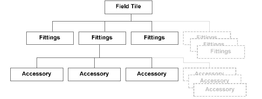
This structure makes it relatively easy to create your “shopping list” and not forget anything as it picks up most things automatically, with the total flexibility of adding, removing or modifying quantities of required items. When viewed in a spreadsheet program (shown in part below The structure can be seen. Field tile and then Fittings with a maximum of 120 accessory items and all 120 lines must be displayed in the spreadsheet whether they contain information or not. The file with field tiles and accessories is called TilesPlus.csv. The associated accessories are stored in a file called Accessories.CSV.
| Supplier |
Name | Material | Profile | Colour | Code |
| Redland | Pantile | Concrete | Interlocking | 5901 | |
| Acc Desc | Code | Mat Cost | Lab Cost | Est Code | Size |
| Redvent Eaves System 350 Centres | 9189 | 1 | 0 | 9 | 4900 |
| Redvent Eaves System 450 Centres | 9189 | 1 | 0 | 9 | 6000 |
| etc. – maximum of 120 lines total | |||||
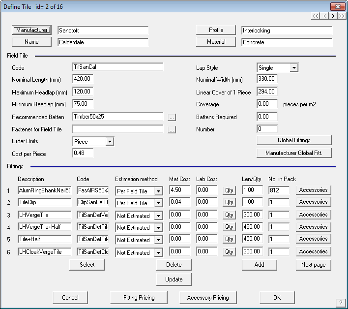
The dialog box is split into 3 discrete areas.
At the top of the dialog is the basic descriptive information regarding this tile profile. That is, you enter the supplier, profile description, tile name and the material for the tile pieces.

File tile description

The central area defines the parameters of the field tile.
Here you define the:
Code The product code of the field tile
Lap style Here you specify if this tile is single or double lap style.
Nominal length The nominal length of the field tile
Nominal width The nominal width of the field tile
Maximum headlap The maximum headlap for the field tiles.
Minimum headlap The minimum headlap for the field tiles. The min/max head lap values are used to define the batten/coursing spacing when the application of the tiles to the roof is simulated. To accommodate for double overlap, you need to set the headlap values appropriately.
Linear cover The exposure of the field tile along the course.
Coverage The number of pieces per square metre or square (10’x10’). This value is used when estimating tile quantities by the area method.
Recommended batten This is the default batten you want to use for this profile. Clicking the ‘…’ button will display all the battens in the material database, from which you can select.
Battens required This is the length of battens (meters or feet) per square metre or square. This value is used when you want to estimate the total length of battens by the area method. If you use the coursing method, this value is not used.
Fastener This is the fastener you want to use for this field tile. Clicking the ‘…’ will display all the fasteners in the material database to select.
Number This is the number of fasteners for each field tile.
Order units This allows you to determine how you would like to order your tiles, either per piece, per square metre (foot), bundle or pallet.

Cost This is the cost of each field tile, per square metre (foot), bundle or pallet.
The lower area defines the fittings associated with this field tile and for each fitting item the additional accessories required. Here you enter the description, product code, estimation method, cost per piece and length/number for each accessory. You can link up to 120 accessories for each tile record.
Accessory area of the dialog
To define the accessories properly, it is necessary to understand the estimation methods. The following table describes the different methods. Note that you can have more than one of each type.
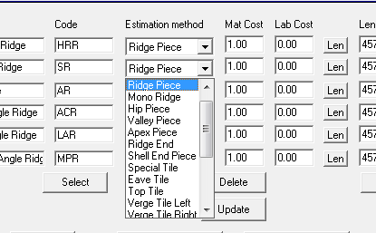
Some of the estimation methods for fittings
| Estimation method | Est Code* | Description | Notes |
| Not estimated | 0 | Fittings marked as “not estimated” will not be estimated. | You can still define accessories, but change their estimation method as you wish. |
| Ridge piece | 1 | The fitting is a ridge piece and estimated based on itslength and the total ridge length | |
| Mono ridge | 2 | The fitting is a mono ridge piece and estimated based on its length and the total mono ridge length | |
| Hip piece | 3 | The fitting is a hip piece and estimated based on its length and the total hip length | |
| Valley piece | 4 | The fitting is a valley piece and estimated based on its length and the total valley length | |
| Apex piece | 5 | The fitting is an apex piece and estimated based the number of hip apexes in the job | |
| Ridge end | 6 | The fitting is a ridge end piece and estimated based on the number of ridge ends in the job. | A ridge end is also called a barge apex. |
| Shell end piece | 7 | The fitting is a shell end piece and estimated based on the number of hip ends in the job. A hip end is the intersection of a hip and eaves. |
|
| Special Tile | 8 | Any tile for any purpose estimated by the width of the piece. Used to account for half tiles, tile and a half tiles and double tiles. Estimated per course or alternate course. |
May also be used to take account of re-use of off-cuts for metal tile. |
| Eave tile | 9 | The fitting is an eave piece and estimated by its length and the eave length in the job. |
|
| Top tile | 10 | The fitting is a top piece and estimated by its length and the ridge length in the job. | |
| Verge Tile Left | 11 | Left hand verge tile, estimated per course or alternate course. | |
| Verge Tile Right | 12 | Right hand verge tile, estimated per course or alternate course. | |
| Step Tile Left | 13 | Left hand step tile, estimated per course or alternate course. | |
| Step Tile Right | 14 | Right hand step tile, estimated per course or alternate course. | |
| Apron Piece | 15 | The fitting is a ridge piece assembly estimated by its length and the total length of ridge in the job. | |
| Miscellaneous | 16 | These are fitting pieces reported on the Reporting dialog box. | |
| Per Course | 17 | These fittings are quantified as a function of the number of courses in the job | |
| Per Code Item | 18 | These fittings are estimated as a function of another piece estimated in the job. | The code field for these pieces includes the code for this itemas well as the code to which this item is linked. The format of this is: ItemCode,LinkCode Where the colon ‘:’delimits the item code and the link code |
| Per Field Tile | 19 | These fittings are estimated as an item with the field tile. |
*The estimation method code relates to the estimation method as displayed in the file when reviewed in a spreadsheet – eg code 18 refers to estimation method ‘Per Code Item’.
The Length/No field holds either the length of a piece (eg ridge, hip) or the number of items required per instance (eg per course, miscellaneous). The item may be quantified as a function of its length or item quantity. Valley, hip and verge pieces can be estimated by cover length, or by coursing. You can have more than one of each type. When you come to select the piece for the actual job later on, (using Cover > Select-Tile), you will then set which actual set of fittings you want.
Fittings estimated as “per code item” may actually be fasteners. Therefore, when the fittings are quantified, the code is searched for in the fasteners database and if found, the cost and ordering information is used from that record.
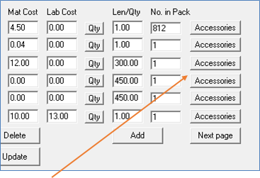
For each fitting, you can also define accessories, or extra material items that help make up the fitting or are required to install the fittings.
By clicking on the accessories field to the right of the fitting, the following dialog box is displayed.
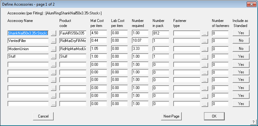
The accessories definition dialog
Items of inventory required for the installation of the field tile or the fitting can be set up using the “Accessories” button alongside that item (see previous dialog).
Fitting Name Is the name of the fitting.
Product Code Is the Product Code of the fitting.
Mat Cost Per Item This is the material cost of the fitting, if applicable.
Lab Cost Per Item This is the labour cost of the accessory, if applicable.
Number Determines how many accessories you require per fitting item.
Fastener Type The type of fastener required for the accessory.
Number Of Fasteners The number of fasteners required for the accessory.
Include As Standard If set to Yes, the accessory is included automatically for that fitting. If set to No, you will need to manually select the accessory to be included.
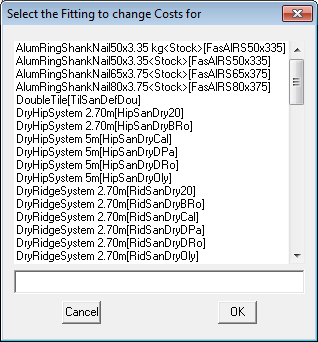
The “…” button allows for the selection of fittings or accessoris respectively and auto-fill in the values obtained from these existing items. You may then change the item as needed and click [OK] to save.
You can set a maximum of 20 accessories per fitting.
The “Include as Standard” option allows the user to define whether the accessory item is automatically inserted when the fitting is selected or whether it needs to be manually inserted by the user.
When you click [OK] the accessories are saved to that fitting, but remember to click [OK] to exit the Tiles+ dialog to ensure that all of your changes are saved.
To make maintenance of the accessory pricing easier, you have Fitting and Accessories Pricing buttons at the bottom the tile dialog. Select this and all the currently defined accessories are listed. Select the one to change or update the material or labour cost, then select [OK] to save the change(s).

Fitting and accessory pricing in the Tiles+ functionality can now be easily modified without the need to recursively track through each fitting or accessory. This function was included due to the complexity of tiling systems in the UK and Europe and now permits much simple management of fitting and accessory pricing.
Select the fitting or accessory item to modify and set Material and/or labour cost.
Select [OK] to save.
For both accessories and accessories, the user must decide whether they wish to include a labour accessory. If so, this accessory will be included into the final Reporting under the labour section, including any other Reporting attributed to the fitting/accessory group through the Reporting > Set Up Reporting Rate > Tiles’ pay rates – variable options (see Labour section for more information on this). The user may decide to use labour pricing based on fittings/accessories alone, based on Reporting > Set Up Reporting Rate > Tilers’ pay rates – variable fields alone or a combination of both.
The data you create using this command is saved in a text data file called TilesPlus.csv in the ..\User folder.
Material data files such as this are best edited from within AppliCad software via the appropriate dialog box, however as they are in a comma separated text file format (CSV) they may also be edited in a spreadsheet program such as Microsoft Excel.
 Flat-Sheet
(for Custom Profile Flashings)
This command allows you to set up custom flashing flat sheet stock material and fabrication costs for turning the flat sheet into flashing. The flat sheet must first be defined so that it is available to select from the material options list when you create and use a custom profile flashing.

Name The name you want to refer to this flat stock material for the custom flashing profiles.
Description A user defined description of the flat stock.
Supplier The supplier of this flat stock material.
Finish The finish of this material (eg painted, colour, galvalume, zincalume etc).
Alternate Category This allows you to give the Flat Sheet an alternate description in the quotation. The default description is ‘Fabrication’. If certain flat stock is used for very specific applications, such as Parapet or Ridge, then this category can be defined and the flat stock will be grouped by this category. This is especially relevant to using Quote Groups and for generating the unique product code for each piece with the Girth and Number of Bends information in the GRIM Out file and the GRIM Supplier Orders. Changing the Alternate Category to anything other than ‘Fabrication’ prevents the product code from including the Girth and Bends.
Stock sheet length The length of the flat stock sheet (not displayed when Estimation method is cut to length (as shown above).
Stock sheet width The width of the flat stock sheet.
Cost of flat sheet The cost to add for the flat stock sheet itself.
Estimation Method This option allows you to define whether the custom profile flashing is fabricated from coil stock as a ‘cut to length’ product or from flat stock as ‘stock lengths’. The cut to length option provides for the fabricator who uses coil stock for his flashings, and wishes to generate the workshop drawings for each flashing profile. In this case the length and width is ignored by the cutting list generating function. The ‘stock length’ option provides for the fabricator who uses precut flat stock to make up the custom profile flashing. Stock sheet length and width is used to determine the number of pieces of flat stock required from inventory to make up the job. The cost of the flat stock may be estimated as well (see below).
Estimate sheets too? If you don’t want the sheets and fabrication cost estimated on the costing, set this value to [No].
Bends These buttons relate to the cost to fabricate a piece with this number of bends. To “open” a column for edit, click on the relevant bend button.
Girths/Stretch-out This is the list of girth or stretch-out increments of cost. The software will automatically find the correct size or the next size up based on girth/stretch-out of the selected Custom Profile flashing using this flat sheet material. The cost for bends will use that girth row in the table.
+/- These buttons allow you to remove and add an extra bend and girth increments. The maximum number of increments for bends is ten. The maximum number of girth increments is fifteen.
Select This button lets you select an existing flat sheet table.
Delete This button lets you delete the current flat sheet table.
Auto-Fill This button displays the Auto-fill dialog box, which prompts you for a cost per cut and a cost per bend. Each cell is then filled in based on the following:
value = cost per cut + cost per bend * number of bends
Add This button lets you Add the current table as a new flat sheet table.
Update This button lets you Update an existing flat sheet table.
[Cancel] This button lets you [Cancel] from this dialog box.
[OK] This button lets you Save the changes you have made.
 Custom-Profiles
The following commands let you create a profile to use as the defining shape of a custom profile flashing, and to assign accessories to that profile.
Once created, Custom-Profiles may be varied at selection time as they are applied to your job. The angle of bend can be varied and the length of each segment can be varied.
With this in mind, one can easily imagine that just a dozen generic profiles could be used to define all your needs. They can also be aggregated under the Assembly function where complex trim systems can be made using multiple trim profiles.
Create
This command creates a profile shape for later use as a custom profile. The process to create a custom profile is:
Draw the required profile exactly to size (using Construct Roof > 2D Design > Track-Lines (from the Icon Menu), or CAD > Line > Insert) and ignore bend radii, they will be accounted as part of the manufacuring tolerance. If you are working in metric, the units are millimetres, in Imperial, insert desired inches.
For example:
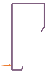
![]() Note: The outline of the profile will look a whole lot better on the report that is generated if the line is heavier so that it stands out on the workshop detail drawing report. Use a line weight of say, 0.75. Feel free to use any other line weight or line style that works for you.
Note: The outline of the profile will look a whole lot better on the report that is generated if the line is heavier so that it stands out on the workshop detail drawing report. Use a line weight of say, 0.75. Feel free to use any other line weight or line style that works for you.
You are then ready to use the lines as the defining shape for the custom flashing.
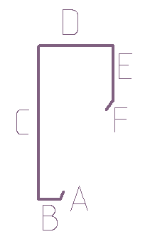
Select Set-Up > More… > Custom-Profiles and the following prompts are displayed. Select Create, and you will be prompted for a profile name to use to define the shape for later recall.
You are then prompted to select the lines and where to insert the segment identifier; select the line and then select the spot where you wish the identifier to appear for each line. The size of the text defaults to 2mm. This may be modified by changing the tag text defaults.
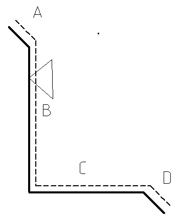
By convention we place the text on the outside, or painted side of the flashing profile. Other conventions might be used to indicate painted side – such as the dashed line or the arrow. These are simply drawn onto the figure, but NOT selected as part of the trim profile during the creation of the part.
Once all the lines are identified, right click and you will be prompted for an installation rate (per metre or per foot) and Minimum and Maximum flashing length (for profiles fabricated from coil stock).

The estimation method used is “Equal Lengths up tothe Maximum Flashing Length”. So, with the Max. Length set at say 8M, a 12M length will produce 2 x 6m, plus the overlaps and run allowances. The Min. Flashing Len value will grey out if we’re in Feet/Inches, as per Min Len for normal flashings.
Select [OK] and this command saves the annotated drawing with lengths and angles of each segment as defaults when you select that custom profile for later use.
The Custom Profile definition may include an arc as well as lines as shown below. The assumption of course is that the press-break or folding machine controller can handle arcs. In such a case the line preceding the arc is used to determine the angle of bend.
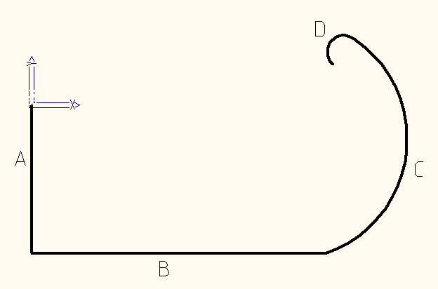
Once defined, you use this new profile by selecting the keyword ‘Custom’ from the flashing list when you want to select a flashing. Refer to the Cover > Flashing command below for details.
![]()
IMPORTANT NOTE: Because the use of the Custom Flashing function allows for modification of the basic parameters of a profile (such as angle of bend or length of an individual segment) as required for various jobs, then you don’t need to define 100’s of profiles. It is anticipated that all the variations for your trim profiles could be easily accommodated in say, 15 to 20 basic profile descriptions. You then adjust the length of individual segments or angle of bend to suit the immediate needs of that job, without defining a whole new profile. These adjustments are applied to the current job and do not affect the original definitions in the custom flashing data file.
Re-Define
The Re-Define option allows you to change the bend order or installation cost details of an existing custom profile definition. If you are modifying and existing profile, Select St-Up > More…> Custom Profile then select Re-Define from the dialog box. The following box is displayed showing all the currently defined profiles and sorted alphabetically. Select the profile you wish to change.

The number of Custom Profiles (up to a maximum of 45 at any one time) displayed in the dialog can be modified by selecting [Options], as well as the size of the preview displayed. – the display of your Custom Profile definitions can be modified to suit the way you work. Select the [Options] button. Select [OK] to save settings.

The following prompt is displayed asking if you really wish to proceed to modify the selected profile. Select Yes to proceed to modify the profile. The previous profile is displayed and the operator is prompted to select the line to apply the segment identifier letter to as described above.
If the profile shape needs to be redefined, it is easier to simply delete the old one and define a new one as described above.
The calculation method for Custom Flashings derived from a Custom Profile set with a “Max. Flashing Length” is currently set to “Split each run up to the maximum length”. Thus, if the “Max. Flashing Len” is set to 6m and the flashing is applied to an 8m line, the resultant flashing will be 2 x 4m flashings. Overlap and Run Allowance settings will obviously affect the resultant value also.
In addition, you may output Custom Flashing product codes, as specified in the Multi-GRIM Quotation Output dialog. This can be enabled through the Supply & Install dialog, allowing these product codes to flow through to the reporting. To enable this operation, the option needs to be turned on through the option on the Set-Up > Preference Settings > System Preferences dialog as displayed below:

GRIM Out Unique Fabrication Codes in Pricing Y/N – , the ability to output Custom Flashing product codes, as specified in the Multi-GRIM Quotation Output dialog, can now be enabled through the Supply & Install dialog also, allowing these product codes to flow through to the reporting. Specification of the file containing the Custom Product Codes then needs to be specified in the Quoting > Multi-GRIM Out > Multi-GRIM for Quotes dialog, with the file containing relevant Product Code structures for each manufacturer.

The ###GIRTH, ###BENDS and ###CODE sub-strings can be used to automate the creation of the new product code – as described in MultiGrim setup.

The resultant product code will then be constructed for each Custom Flashing and will appear in the Supply & Install dialog and flow through to the reporting, thus ensuring all reporting and GRIM output results match.

Accessories
This command lets you assign the required accessories to a custom profile you have prepared. To assign accessories, you are prompted to select a custom profile from the dialog box and the one you just defined will be displayed.
After selecting the particular profile (by clicking the button below the picture of the profile), the Define Accessories dialog box is displayed.
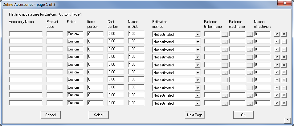
Here you define the list of accessories you want to use with the profile. After entering a name and a product code, you need to enter the finish of the accessory. Refer to the description of this process above. By default, the accessory will adopt the finish of the stock sheet to which the profile will be selected. If you do not want that to happen, then you can enter the finish you want (eg Painted, zincalume, galv, etc).
Then you enter how many items there are in a box, the cost per box and the estimation “number”. To get more details about the “number” and the estimation method, please refer to the Set-Up > Flashing command above.
The [M] button toggles between [M] and [L] signifying whether the accessory is reported as a labour item or a material item when you cost the job using these profiles.
The [X] buttons at the end of the accessory description allow you to delete a previously defined accessory item.
Delete
The delete button allows you to delete a previously defined profile.
Membrane
(Pulldown Menu Only)
This command allows you to set up membrane definitions for all types of low slope roofing. Materials such as modified bitumen, EPDM single ply membranes, inter-ply, cap sheet and roof ballast materials. Once defined, the materials are aggregated to make a roof system – refer to Cover > Membrane.

Asphalt and other adhesive materials may also be defined as a liquid Fastener – refer Set-Up > Fastener.
Supplier This button lists all the suppliers in the membrane database from which you select one by clicking the button picking from a list. You can also enter a new supplier’s name directly into the supplier field.
Name This button lists names in the membrane database from which you can select one to re-use. You can also enter a new name directly into the name field.
Code This is the membrane product code.
Description This is a free form description for you to select insulation.
Unit type This drop down menu allows you to select from rolls, sheets, drums, Kilograms or Tonnes.
For BUR roofing materials, the following values are used for the estimation.
Large size The coverage of the large size (drum, kilo or ton)
Small size The coverage of the small size (drum, kilo or ton).
Cost of large size The cost of the large size.
Cost of small size The cost of the small size.
For single-ply roofing materials, the following values are used for the estimation and layout. You may define different parameters for field and perimeter materials.
Perimeter sheet width The width of the perimeter sheet/roll
Length The length of a long perimeter roll
Length The length of a short perimeter roll
Cost The cost of a long perimeter roll
Cost The cost of a short perimeter roll
Field sheet width The width of the field sheet/roll
Length The length of a long field roll
Length The length of a short field roll
Cost The cost of a long field roll
Cost The cost of a short field roll
Select This button lists all the membrane records in the database from which you can select one to view, edit or delete
Delete This button deletes the current definition
Add This button adds the current definition to the database as long as it is unique
Update This button appears only after you have selected Select. This button then updates the current record with the current details
[Cancel] This button cancels all changes you have made
[OK] This button saves the changes you have made to a data file called – membrane.csv in the ..\User folder.
Material data files such as this are best edited from within AppliCad software via the appropriate dialog box, however as they are in a comma separated text file format (CSV) they may also be edited in a spreadsheet program.
 Flashing Assemblies
This function has been developed especially for commercial metal roofing enterprises dealing with many 100’s or even 1000’s of variations of panel, flashing and trim combinations using what we call Assembly Groups. The purpose of an Assembly Group is to link a group of Flashing Assemblies to specific roofing or wall cladding panels. Use of the Assembly Groups is optional and should only be used if you know that you need the level of complexity this entails.
The Assembly Manager allows you to set up roof flashing assembly details and associate the detail with the metal panel and automatically include the correct trim and accessories for the structural situation. This is done by defining an Assembly Group. It allows you to have the same panel/flashing items used in various configurations as well as define rules for how and when they will be used. For example, a fastener that is used to install a trim item or bracket on a structure with ply deck substrate will not be suitable for the same trim or bracket on an open frame structure.
These definitions may comprise one or many flashing items as well as a flashing detail graphic saved as a CAD sub-figure for illustrating your client proposal. If a graphic is specified, you are prompted to use it when you apply the flashing assembly to your job.

This is the dialog for Assemblies in Non-Commercial mode.
Each flashing and associated accessory items selected for use in an assembly must exist already as a standard profile or custom flashing profile material as described in preceding sections on Flashings (described above).
Name of flashing assembly This is the name you define for this flashing detail. You will use this name later when selecting flashing or edge assembly details.
Database name of graphic detail This is the name of the CAD database (*.dab file) containing the subfigure of the graphic detail (the next field). When you click this field, you can select the database you want. The default database name is EdgeAssembly.dab.
Figure name of graphic detail This is the name of the subfigure to be inserted when you select this flashing assembly or detail. When you click this field, the list of subfigures in the given CAD database name are listed. From this list, you select the one you want. You must draw from scratch the illustration of the detail using regular CAD drafting tools (found in the Pulldown Menu – CAD). You may also import details from other CAD files in DXF format.
Add-Flashing This allows you to add a flashing item to the list of flashings that define this edge or flashing assembly.
Add-Accessory This allows you to add ab accessory item to the list.
Add-fastener This allows you to add a fastener to the list.
Modify/New This allows you to select an existing flashing assembly definition or add a new flashing assembly definition.
When you click [OK], the details are stored in the binary data file called – EdgeAss.csv in the ..\User folder.
Material data files such as this are best edited from within AppliCad software via the appropriate dialog box, however as they are in a comma separated text file format (CSV) they may also be edited in a spreadsheet program.
Assembly Manager operates in 2 different modes ‘Non-Commercial’ or regular mode or ‘Commercial’ mode with full Assembly Manager capability. These modes are set by selecting ‘Commercial Mode’ – on/off under Set-Up > Preferences > System Preferences. It is advised that you do not select ‘Commercial’ mode if it is not required, as it does create extra work to maintain. The default setup is with Commercial Mode – Off.
In Commercial mode, the assemblies are assumed to be complex and that there will be many of them (typically > 500) and so the assemblies are stored in a binary format (non man-readable *.db files) for faster software access. Assemblies are grouped according to Assembly Groups that must first be set up in order to define the binary files that assemblies can then be stored within.
Non-Commercial Mode
In Non-Commercial Mode, the software operates as described above – Flashing Assemblies.
Assemblies are stored in the EdgeAss.CSV file and displayed on the dialog box as follows:
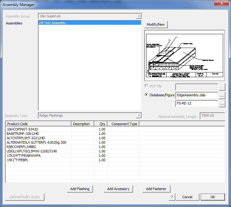
Assembly Manager – Non-Commercial Mode
Assembly Manager dialog box has certain functionality disabled in Non-Commercial mode.
In Non-Commercial mode, you do not have groups defined and you cannot define rules for application of the assembly. It is simplified in so far as you have an image to illustrate your report; you have all the flashing, accessory and fastener items required to install the assembly and that is the only option.

Note that if your selected accessories, flashing or fastener files cannot be found, they will display in red as shown here. It is a prompt for you to ensure that the respective data files are in the same location as your assembly.
Assembly Groups (described below), Types, Nominal Lengths, PDF File and Rules are all disabled in non-commercial mode. Modify/New allows you to modify an existing assembly or add a new assembly.
Selecting [OK] saves away the current assemblies list to the file EdgeAss.CSV in the ..\User folder.
Commercial Mode
Commercial Mode is turned on in the System Preferences – Set-up > Preference Settings > System Preferences. The default Roof Wizard setup is with Commercial Mode – Off.
As explained above, in Commercial mode the assemblies are assumed to be complex and that there will be many of them (typically > 500) and so the assemblies are stored in a binary format (non man-readable *.db files) for faster software access. Assemblies are grouped according to Assembly Groups that must first be set up in order to define the binary files that assemblies can then be stored within.
![]()
IMPORTANT – Please note that to use the additional functionality that commercial mode allows for, the maximum number of characters in your product codes for flashings, fasteners and accessories is limited to 10 characters. The same rules apply as regards no special characters such as !,@,#,$,5,6,7,* etc.
This is due to a constraint of the commercial mode data structure that provides the required connections between all the items.
Assembly Groups
To create an Assembly Group, the user will go to the Set-Up > More… >Assembly-Groups menu and simply create a group by naming it in this dialog:
The creation of an Assembly Group then allows the user to link a group of Flashing Assemblies to a specific group of roofing or wall cladding panels when they are defined. Note that this link can only be made after the panels, flashings, accessories and fasteners have been defined under Setup, and ‘Commercial’ mode is enabled in Preferences.
Assigning a Panel to an Assembly Group
In Commercial mode, a specific Assembly Group will be assigned to roof and wall panels. This is done by accessing the Set-Up -> Metal-Panels function and selecting the Assembly Group from the drop-down option in the dialog:
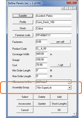
Important Note: If you have no intention of using Assembly Groups, then you will not have Commercial mode enabled and you do not have the option to select an Assembly Group when you define your new panel profile – you will be running in Non-Commercial mode. Turn Commercial Mode on/off in Set-up > Preference Settings > System Preferences.
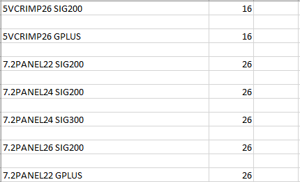
Alternately, the linkages between panels and Assembly Groups are stored outside the software in a file called SgroupLink.CSV. This file can be modified manually in a text editor or MS Excel, although care must be taken to use the correct product code from the panel and the index of the Assembly Group.
Assembly Manager – Commercial Mode
In commercial mode, the Assembly Manager takes on extra functionality. This functionality provides for Assembly Groups.
Assembly Group – Allows the user to select which Assembly Group we are looking at and substantially reduces the complexity in numbers of Assemblies being modified. [Modify/New] allows the Assembly Groups to be modified, created or deleted.
Assemblies – allows the user to select, create, modify and delete assemblies that relate to selected the Assembly Group.
PDF File – As well as defining a CAD database/figure being specified to indicate how an assembly is to be installed, a PDF file can be specified for commercial customers. At a later stage in the process, the PDF files can be grouped together and printed en-masse to produce a document set for installation of this specific project. The PDF documents may be any selection of previously created technical specification or installation detail documents.
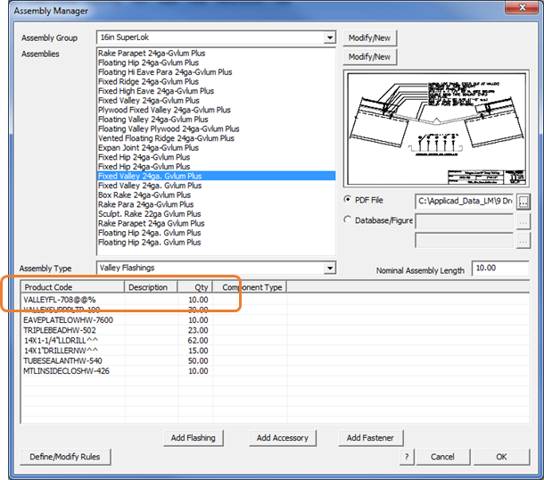
Assembly Type – Allows an Assembly to have a type assigned to it, so that it can only be assigned to certain line types within the software – for example, in the dialog above, the Assembly has been defined as a Valley type and as such, will be listed among options for a Valley line type and can only be applied to Valley lines on your model. Below this is the list of items (flashings, accessories, fasteners) that are required to install the assembly and the rules that control the use of each item. These are added using the [Add …] buttons.
For each assembly you can have a maximum of 20 component items.
Nominal Assembly Length – Allows a notional length to be specified for the selected assembly for costing purposes, thereby making the specification of quantities for parts and pieces of the assembly much less complex. For instance, in many markets such as North America many assemblies are specified in 10’ length multiples – a function of the flat stock and fabrication machines used in production. This becomes the base unit for associating the components with the assembly.
Assembly Manager Rules
Rules can be created for Assemblies that allow the software to automatically swap parts in or out of an assembly, based on various decisions made during a project setup.
For example, let’s assume we have five different valley flashings, with the following product codes:
VALLEY22G – 22 Gauge Valley Flashing - Galvanized
VALLEY24G – 24 Gauge Valley Flashing - Galvanized
VALLEY22C – 22 Gauge Valley Flashing - Painted
VALLEY24C – 24 Gauge Valley Flashing - Painted
VALLEY24X – 24 Gauge Valley Flashing - Hi-Protective Coating
If we were to define an Assembly that used this flashing category, we would need to take into account all of the different valley flashing options of gauge and finish and create many separate flashing definitions to cover these.
Instead, Roof Wizard allows us to define a flashing with variable values that can include universal variables that look like this – VALLEY@@% – where the product code is VALLEY and the @@ symbols and the % symbol are ‘placeholder text’ used to replace the product gauge and finish, to be automatically replaced at assembly selection time, as determined by the definition of the roof panel material selected.
This allows the product code for the correct flashing to be substantially simplified and automatically built up by the software as shown below with the example SCLPTRDGUTFL-247A@@% and @@ is replaced with the required gauge and the % is replaced with the abbreviation for the required finish that matches the panel profile in use on the job.
In the example above, a 16″ SuperLok was selected, and if the finish was a painted, 22 gauge profile the product code for the associated valley might be SCLPTRDGUTFL-247A22P, but the Product Code Rules will select this automatically for you, based on the panel selected.
The number of symbols required must match the number of characters being replaced for example @@ = 22 or 24, that is two number characters. If you change the product code and it doesn’t match the product code structure, then the whole part is displayed in RED (as shown below) – indicating that the number of character replacements doesn’t match the form of the existing product code.
Once changed in the Assembly Group setup, select [OK] and the data is saved to the respective database file in the ..\User folder.
Note: this process presumes that your product codes are organized in an orderly way. If the product codes in your organization are not organized in a sequential way as shown in our example, you will struggle to use the rules to reduce the number of assemblies you need to define. The product code structure you implement for trim and flashing items is key to the success of the Assembly Manager in managing huge product component lists.
Select the button [Add Flashing] to add a flashing to the assembly list. The regular flashing product code as initially defined will be displayed.
In this example, the FL-265 Sculptured High Eave incorporates 22 and D in the product code as shown here:

When we get to the Assembly Manager, we wish to put placeholder text in their place so that the various guages and finishes on offer for the roof panel will be automatically translated to the entire trim system.
Double click the Product Code cell for the product you wish to add ‘placeholder text’ so that the substitution can be made as described above. Any change and the software will indicate that the change does not match with an existing code by turning the whole entry red.

Use [Tab] or [Enter] to exit the edit and if you have correctly modified the product code to include the placeholder text, it will go to a normal listing.

If the product code doesn’t match or is incorrect in any way, the Assembly Manager cannot relate it back to your original flashing definitions, then it lets you know by displaying the item in red.
Once the item is correctly defined and displays normally in your list, you must then define the rules to be applied to the placeholder text.

Rules can then be set up similar to the following examples:
The first rule below (Replace 22 gauge rule) tells the software to replace any instance of @@ in the Assembly Product Codes with the value of 22, when the roof panel gauge is 22. The second rule tells the software to replace any instance of % in the Assembly Product Codes with G if the finish of the selected roof panel product is set to “Galvalume Plus” as shown in the examples below:
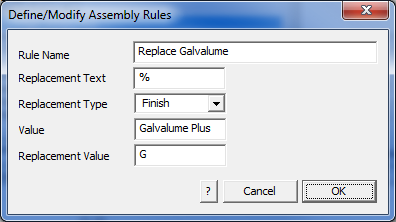
‘Value’ is the value of the gauge or finish selected for the panel. ‘Replacement Value‘ is the value that replaced your placeholder text in the product code in the Assembly manager setup dialog, such as @@ or %, e.g. Value = Galvalume Plus, Replacement Value = G or Value = CF45, Replacement Value = CF.
There is no practical limit to the number of rules that you can set. This makes for a very powerful tool to manage even the most complex roof and wall trim systems automatically.
Extended Rule Options
This set of rule options is independent of the Product Code Rules and operates separate from them.
By double clicking in the cell for the rules for an item, you can specify five specific rules per flashing, accessory or fastener to vary the component item configuration for certain quite specific panel arrangements.


This allows you to set a very specific selection of items based on Gauge, Finish, Substrate, System and Coverage. It also allows you to AND and OR these rules together. The ANDs and ORs are applied left to right. So, if you want (A OR B) AND C you’d simple put A OR B AND C. But, if you want A OR (B AND C), you’d need to test these first 2, such as B AND C OR A.
The rules for Assembly Groups are stored in a file called AssRuleValues.dat and is in the form of:

This example has various rules pertaining to the Gauge, Finish, Substrate, and System. Note each variable is terminated with the word END. This file is automatically created by the software in the ..\User folder.
How Assemblies Work
If we have a scenario where we have structural options of open frame, metal deck or ply deck then the variation for trim and asseccories between the systems is substantial. Similar maybe, but definitely NOT the same. So, we create the assemblies and an assembly group.
For each assembly type any flashing, accessory or fastener item described by its product can be added and then you define whether it is always included, or included based on a defined rule.

The two flashing items highlighted above are similar, but one is used when the panel is ACG and the other when the panel is PVDF based on the rule IF Finish is ACG use part 5700241 and IF Finish = PCDF use part 58002; and so on for all other parts that make up this Flashing Assembly based on the rules for finish, gauge (if appropriate), substrate etc as defined. Note that the part 6403899 – Double Bead Tape Sealant is Always used – no need for a rule.

[1] – The Assembly Group name.
[2] – The flashing assembly for the specific Ridge or Hip condition
[3] – the reference to the PDF document that illustrates this Assembly Group.
[4] – The Product Code Rules.
Select the Include by Product Code Rules button and then define the rule based on predefined variables for Gauge or Finish.

Define additional rules for when an item is included or not.
Select the Include by Rule cell and then define the rule based on predefined variables for Gauge, Finish, Substrate or System.

The rule statement is displayed eg [IF Gauge = 24] in the Rule column.
Once the Assembly is defined, select [OK] and the setup is saved to a binary database file (a DB file eg ’16″_Vertical_Seam.db’ ) to ensure quick access by the software when building the material list for your project.
[5] – The exact flashing and accessory items with rules for each item.
Using this definition, we can apply it to our roof model with Vertical Seam 16″ panel,
and generate the flashing cutting lists and for
Vertical Seam (Str) 16” 22.0Ga. ACG Open Framing – we get this list:

For Vertical Seam (Str) 16” 22.0Ga. PVDF Open Framing, we get this list:

And for Vertical Seam (Str) 16” 22.0Ga. PVDF Open Framing we get this list.

While the description of some parts may be the same or even just similar, the part numbers or product codes are unique to that part for that purpose. So you can see from this that any combination or permutation of flashing and accessories can be combined with any panel.
Very powerful stuff, but considerable effort to set up. Once done however, it is then simply a matter of maintenance.
Importing Assembly Data
Importing the assembly data from external databases, inventory or ERP systems is also possible. To achieve this, you must export the data into a CSV file that you can review in MS Excel. It may be exported from such systems using an MS Excel macro or special utility but MUST be in the correct format as shown here.

To access the import utility to import the data you have created, turn on the right-hand menu – Menu On from the Pulldown. Select Set-Up from the main menu on the right and you will get the following dialog box. Select the [Create-Assembly-Databases] option.

A standard Windows Explorer dialog box is displayed where you can select the previous saved data file. You will be prompted to create the AssemblyGroups.

Select the previously defined file –

Confirm as prompted and all the assembly groups with the flashing and accessory data will be automatically created saving hours and hours of time doing it manually, one line at a time.
The assembly type comes from one of the following values for the Assembly Type column in the Assembly_Definitions.CSV file:
0: Custom Flashings
1: Ridge Flashings
2: Valley Flashings
3: Fascia Flashings
4: Gutter Flashings
5: Gable Flashings
6: Apron Flashings
7: Batten Flashings
8: Box-Gutter Flashings
9: User Len Flashings
10: Fascia/Barge Flashings
11: Step Flashings
12: External Wall Corner Flashings
13: Internal Wall Corner Flashings
14: Window Sill Flashings
15: Window Edge Flashings
16: Window Head Flashings
17: Door Edge Flashings
18: Door Head Flashings
19: Hip Flashings
20: Wall Top Flashings
21: Wall Bottom Flashings
22: User1 Flashings
23: User2 Flashings
24: User3 Flashings
25: User4 Flashings
26: Wall Batten Flashings
27: Roof Flashings
28: Wall Flashings
29: Door Flashings
30: Window Flashings
31: Window/Door Flashings
32: Roof/Wall Flashings
![]()
NOTE: It is very wise when setting up, to start with simple examples and test that you have done it correctly before you launch yourself at the entire product list in your company.
 Fixtures
Define a roof fixture or edit an existing one. You would use this command to define such roof objects as skylights, ventilators, drains, downpipe penetrations etc. for the roof job. They may be set up to be fixed size or defined parametrically, that is an operator specified size on placement. This provides ultimate control over the use of roof mounted hardware. As is the case for defining all products in Roof Wizard, the key item in the definition is the Product Code – it is this that links the products with the accessories, the pricing and labour etc.
When you select this command, the Define Fixture dialog box is displayed, with a preview of the symbol for the Fixture:

Name of fixture This is the name you define for this fixture. You will use this name later when selecting fixtures.
Supplier The name of the fixture supplier
Product code The code of this fixture.
Flashing The code of the first flashing associated with this fixture. This is only displayed if a flashing item has been selected. Additional flashings are added as required to complete the installation of the fixture. By default, all other items required by the flashing are also included as they are accessories to the flashing. Defining a User Defined Flashing item can be used to pick up obscure items such wiring on PV cells for example.
![]()
Note: If Custom Profile flashings are selected as flashing items, then they must be inserted within the first three items in the list or they will not be calculated in the cutting list.
Alternate Category To allow you to specify a different category other than Fixtures when using Quote-Groups.
Figure Type They may be set up to be fixed size or defined parametrically//help.applicad.com/setup/#Quote-Groups/, that is an operator specified size on placement.
The options are :
Figure – Fixed Size – whatever size the item Sub-Figure is drawn is the size it will be inserted onto the roof model;
Figure – Scalable – allows the operator to define items that may be scaled in X,Y, or Z on placement into the roof model. A very useful tool when defining items such as trees.
The option Parametric Box allows generic figures such as HVAC units or chimneys to be defined as a rectangular box and inserted at whatever size is required.
Parametric Cylinder allows for generic tube-like objects to be placed on the roof model, such as vent pipes etc.
In use, the operator is also prompted for a Fixture Label so that a table of fixtures can be reported on the client proposal, as well as control over colours and line weight etc. as well as the annotation text.


Database name of fixture This is the name of the database (.dab file) containing the subfigure of the graphic detail (the next field). When you click this field, you can select the database you want. The default database name is Fixtures.dab in the ..\User folder.
Figure name of fixture This is the name of the subfigure to be inserted when you select this fixture. When you click this field, the list of subfigures in the given database name are listed. From this list, you select the one you want. Figures to illustrate the fixture may be drawn in full 3D within the software using the CAD tools included or imported from another CAD system as a DXF file.
Anything may be modelled and saved as a Sub-Figure – [File > Sub-Figure > Save-As]. Include as much or as little information as you require to adequately illustrate the part. We save the graphics representing the part as a Sub-Figure. The sub-figures may be saved in various files eg you might save the tree figures in a database called tress.dab and the PV Panels in a file called PVPanels.dab. We find it easier to manage of the figures are saved in the same database ie fixtures.dab. Note that a figure is not the same as a model. In the typical use of CAD to design buildings for example, a sub-figure may be a window or a door that you model and then re-use over and over in subsequent documentation.
Insertion method This is one of Get a location and orientation point (such as a rectangular skylight), Get a Location Point Only (such as a circular drain), Insert Along a Line Entity (such as a penetration in a gutter or along a pipe); Get a Location and Orientation Point so that the operator can snap to existing geometry points to establish the placement and orientation of the fixture.
Cost The cost of this fixture.
Cost to install The cost to install this fixture.
Create Hole for Fixture Provides for the situation where a hole needs to be cut so that material under the fixture does not count in the total material for the roof cladding – such as a large item like a HVAC unit. Set [Yes] or [No] as required.
Insert on Plane If set to No, the fixture is inserted onto the Construction Plane (CPL). If set to Yes, it is placed on the plane of the roof above the point selected on screen.

Left fixture = Flat to Roof Plane Right fixtures = Flat to CPL
Add-Flashing This allows you to add a flashing to the list of flashings which you want associated with this fixture.
Delete-Flashing This allows you to remove a flashing from the flashing list.
Select This allows you to select an existing fixture.
Add This allows you to add a new fixture.
Delete This allows you to delete an existing fixture.
Update This allows you to update an existing fixture after changes are made.
To save your definitions you must click [OK].
These definitions are saved in the file Fixtures.dab regardless of which database file name the subfigures (the drawing of the fixture) are saved. To save confusion, it is recommended that all sub-figures are saved in the CAD database file fixtures.dab in the ..\User folder.
 Downpipes
This command lets you define downpipes and their accessories. In some markets, downpipes may also be referred to as downspouts – the process for defining and using them is the same.
When you select this command, the Set-Up > Downpipe dialog box is displayed.

Supplier The supplier of this downpipe.
Finish The finish of this downpipe.
Description The style of this downpipe as either Round or Rectangular as required to identify it.
Thickness The thickness or gauge of the material of this downpipe.
Length You can specify 2 standard lengths for the downpipe pieces as well as the product codes and costs for each length.
Estimation method You can set the take-off as “per spout” or “add total spout length” in order to calculate the number of lengths required.
When you select this command, the Set-Up > Downpipe dialog box is displayed.
Accessories You can specify the product code and cost for all accessory items such as the pop (or dropper), straps, offset, shoe and elbow associated with this downpipe. For the strap, you can specify the spacing between straps so that the number of straps can be estimated. Depending on what you want to supply, you can report or not report any of the accessories – item cost and for straps, the frequency or spacing along the downpipe.

The product code of the accessory is used for ordering, but it is also the key that links the accessory item to a downpipe item in the system. The important thing to get correct here is the ‘estimation method’. The correct association between the accessory and the tile is how the software gets your material orders perfect every time.
Spaced Along DP adds the accessory item at the distance interval set under Number or Distance (for example, DP straps).
Per DP adds an accessory item per downpipe, for example, a dropper or pop.
Per DP (Offset) allows you to add an offset from the wall to the eave, and you will be prompted to subtract from DP length (if required) when used.
Optional (included) adds the item automatically for each DP instance, but may be removed.
Optional (excluded) provides for it in the list but must be selected by the operator when used.
Per Join adds the item at a DP joint
Add This allows you to add a downpipe
Delete This allows you to delete the selected downpipe.
Select This allows you to select an existing downpipe.
Update This allows you to update a selected downpipe.
[OK] Closes the dialog and saves the changes you have made.
[Cancel] Closes the dialog without saving the changes you have made.
The information is saved to the file downpipes_v6.csv and DPaccess.csv in the ..\User folder.
Material data files such as this are best edited from within AppliCad software via the appropriate dialog box, however as they are in a comma separated text file format (CSV) they may also be edited in a spreadsheet program.
![]() Notes on downpipes and accessories:
Notes on downpipes and accessories:
In some markets, the roofer doesn’t install the downpipes, but they do install the outlets for them when they install the fascia and gutter. (Outlets also go by the name of pops, spigot’s, nozzles etc, so take this into account in this explanation). Since the roofer doesn’t need to bother with downpipes in this scenario, he only needs the outlet, then we have a definition trick we can apply to allow the outlet to be quantified without the downpipe. For some contractors, this might effectively duplicate the number of items defined – outlets by themselves and downpipes with outlets.
First go to Setup > More > Downpipes. Then define a downpipe that is actually an outlet. For example:
Similar to this, noting that the description is for an outlet [1] so you can select the correct item, and there is no product code or other definition for the actual downpipe [2], since we don’t actually want a downpipe.

Select [Add] since this is a new item in your list.
Next select the Accessories button to add an accessory to this false “downpipe”, giving it the required description, product code and cost etc and the estimation method of ‘per downpipe’. Then select [Update] and the select [OK] (to save the new definition).

Then when you apply the “downpipe”, which is actually an outlet, you get the dot indicating the required location on the roof plan report for your installers,

AND you get the outlet in your parts list. Note that the line item category is a downpipe accessory.

Done.
 Extra-Items
This command lets you define a series of labour and material extras that will be automatically added to each of your quotes (under Reporting > Supply-Only and Reporting > Supply-Install). These are items that you always include as part of a job quote or bid. Select Set-Up >More…> Extra Items. When you select this command, the following dialog box is displayed:

Here you simply select [Add New] enter the line item Supplier, Description, Product Code (if required, but recommended), material quantity and cost per item and labour quantity and cost per item. Labour items will be displayed in the labour sub-total, and material items will be displayed in the quotation page.
The key to success with Extras is to set the appropriate estimation method from the drop-down box, for that item:
Use Quantity Alone – use the quantity specified.
Multiply Quantity by Roof Area – multiply the quantity by the roof area to arrive at the required number.
Spaced along… (all roof model line types may be used including ridge, hip valley and even wall lines and battens).

You must also specifiy whether the item is a labour or material category item. You may also set whether the item is always used or whether you should be prompted for its use [Both/Select] in the [Utilisation] column. The last column allows you to set an alternate category so that old versions of the file with miscellaneous items files can be used.
![]() Hint – You may also use this list as a useful way to create a ‘check list’ on your proposal – create an Extra item with a quantity of zero. It will appear on the list as a reminder to add it by changing the quantity to the required number. Zero items may be set to NOT print when the proposal is being prepared. This is in addition to using the Utilisation attribute.
Hint – You may also use this list as a useful way to create a ‘check list’ on your proposal – create an Extra item with a quantity of zero. It will appear on the list as a reminder to add it by changing the quantity to the required number. Zero items may be set to NOT print when the proposal is being prepared. This is in addition to using the Utilisation attribute.
When you click [OK], the details are saved in a file called extras_v6.csv in the ..\User folder.
Misc-Items
This command lets you define a series of material items which you can select from using Reporting > Supply > Misc-Items.
This function was merged with Extras_v6.csv from Version 8.1 of Roof Wizard.
Refer to that description above. The file called misc.csv is merged with Extras_v6.csv automatically with the installation of V8.1.
Area-Names
(Pulldown Menu)
This command lets you define the delivery area names and rates you want to select from using Job-Info > The Job-Details command.

You can also set the line item label when displayed on the Reporting dialog box (Reporting > Supply+Install) and choose to include or exclude this line item.
You may define as many as 1000 different area names if required. Type the new area name, set the rate and select [Add].
Select [Modify] to change the details of an area name.
When you click [OK], the details are saved in the data file called – areas.csv in the ..\User folder.
Note: tile distributors may also define a cartage rate per 100 tiles. If this is defined, cartage and delivery can both be listed in the reporting dialog. Refer to Set-Up > Set up Pay Rates > Tile Rates–Fixed for a description of that.
 People
Customer, Installer, Builder, Salesman and Distributor
These commands let you set the particular person against each of these roles. When you select the particular role, the Select person details dialog box is displayed.
Here you can set or select the person you want. In this case, we are looking at the Customer role, but the same goes for all roles.

Name The name of the person or company
Contact The contact name
Address The 3 line address
Phone The phone number
Fax The fax number
Mobile The mobile/cell number
Discount The discount used for this customer. This is only preset for this Customer. This is the default value used when you do a job Reporting and applies the discount rate to all items unless modified by the next option – Set Discount Structure.
Discount Structure Allows the operator set up different discounts for different line items (see below):
Business No. Customer’s business number.
Company No Customer’s business number.
Company Logo Save a bitmap image file of the customer’s logo so that you may include it on a report for them – TIF, JPG, PCX, GIF, BMP etc. This as saved with the customer’s record, and automatically inserted into a report using the key text string ###Image[CustLogo.jpg] and a software function that replaces the following files with their listed replacements:
CustLogo.JPG jobData[0].cust.image //The Company Logo from currently selected Customer record
And it does the same for the other categories of ‘People’ in the system.
InstallLogo.JPG jobData[0].installer.image //The Company Logo from currently selected Installer record
BuildLogo.JPG jobData[0].builder.image //The Company Logo from currently selected Builder record
SalesLogo.JPG jobData[0].sales.image //The Company Logo from currently selected SalesPerson record
SuppLogo.JPG jobData[0].distrib.image //The Company Logo from currently selected Supplier record
JobImage.JPG jobData[0].job2.startMode[11] //The Supplier Image path as set in Job Details
Select Any Allows you to select any existing entity from the People file (a builder or installer for example) as a customer.
![]()
Note: You may wish to set up the details of all of your Suppliers, Customers, Installers prior to use, or you may wish to set this information on a job-by-job basis. Information can be added at any stage in the process. There is a file limit of 2000 records (Suppliers, Customers, Installers) in this list.
You can enter values as you wish and click [OK] to save that person. For more details about setting discount structures, go to the Reference Manual.
When all of the fields have been set, click on Add-Customer and your new customer will be added to the customer database. If you would like to choose an existing customer click on Sel-Customer and a dialog box similar to the following will appear, showing you all of the existing customers in the customer database.
To select an existing customer, click on a name and then click [OK]. This will now bring up that particular customer’s details in the select customer details dialog box. With this all now done click [OK] and these customer details will be put on the quotation form. You can also modify the customer’s details and click Update to save the changes. This process is identical for the Installer, Builder, Salesman and Distributor information and saved in the file we call People_v6.csv in the ..\User folder. The file may be edited via MS Excel if you are expert in the use of MS Excel. If not, modify te file from within the Roof Wizard.

Default Material Markup/Default Labour Markup – these options may be set for each customer and over-ride the markup settings for just this customer. These are applied when you select the Costing > Supply Only or Costing > Supply and Install options under the Reporting menu group, for calculating the total labour and material costs. The setup for pricing is based around either a cost price plus a markup, OR a sell price less a discount, and these settings are designed to set a price structure for EACH CUSTOMER providing flexibility in pricing for the sales team.
What is important to note is that you cannot mix and match – you are doing all customers as ‘cost price plus Markup’ or all customers as ‘selling price minus Discount’. We are not talking about margins or profit here – that is an accounting function. The assumption is that you have figured out what gross margin you wish to get in setting the sell price for each item. Markup is a percentage increase on the cost price that provides you a profit. Margin is a percentage profit on the sell price usually referred to as gross profit or profit before operating costs.
There is also additional flexibility if you wish to discount individual product groups for each customer. The software creates a discount structure as a separate file for each customer in the ..\User folder when you invoke that, based on a discount structure template file called Cust-Discount-Template.DAT.
When you select the option, [Set Discount Structure], the following dialog box is displayed. This provides for the situation where all your customers are given different discounts rates for different product categories.
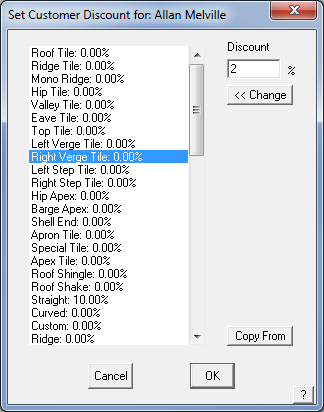
The product category name is as displayed on the Reporting screen when a job is quoted. Select a product category from the list in the left pane, set the required discount rate and select <<Change. You may also copy the rates from another customer’s discount file. Select Copy From, select the customer whose discount file you wish to copy to this customer. Make any further edits you need, then select [OK] to save the details.
When you select [OK], a text file is created that sets up these rates for this particular customer. The file is a simple text file or ‘flat file’ structure and may be viewed or edited in a word processing program.
It is in the form as displayed below.
Roof Tiles:0.000000
Ridge Tiles:0.000000
Mono Ridge:0.000000
Hip Tiles:0.000000
Valley Tiles:0.000000
Left Verge Tile:0.000000
Right Verge Tile:0.000000
Left Step Tile:8.000000
Apron Tile:0.000000
Special Tile:0.000000
Apex Tile:0.000000
Roof Shingle:0.000000
Roof Shake:0.000000……
…… etc
The file name is automatically given by the software and is in the form of –
<CustomerName>_CustDisc.DAT where <CustomerName> is extracted from the customer’s name that you entered in the Set Customer Details dialog.
You can enter values as you wish and click [OK] to save that Customer to the text data file called – people2.dat. This allows the file to be viewed and edited in external editors such as Notepad or Microsoft Excel.
You can also select a new customer from the list of customers by clicking Sel Customer.
You can delete the current customer by clicking Del Customer,
You can add a new customer to the person database by clicking Add Customer.
Select Load Last and the last customer you were editing will be displayed.
If you want to select from the entire database, select the Select any person button.
If you want to update an existing person, first select the person. An Update button then appears on the dialog box. Make your changes, then click Update which then updates that person back into the database.
The structure is set in a ‘template’ file called Cust-Discount-Template.dat that must exist before this process will work.
Export-People
This command lets you export the people2.dat file to an ascii text file called people.csv. Then you can transfer the ascii file into another program (eg Microsoft Excel), make changes then import the file using Import-People. To help, the following dialog box is displayed.
Import-People
This command lets you import (convert) people_v6.csv to people2.dat. This function allows you to create a text file of your people information in another program, such as a spreadsheet, or export from a program such as your accounting system or a customer relationship management (CRM) program.
The format must match the syntax and format of the people2.dat file – to review this, export the file from AppliCad Roof Wizard, then review the format in a text editor.
Curving-Charges
(Pulldown Menu Only)
This command lets you define the list of curving charges for a particular metal panel profile. When you click the command, the following dialog box is displayed.

You must first select the metal panel by clicking the ‘…’ button to the right of the Curving Material field. Note that only those profiles you defined as curve quality will be listed.
To define a profile as curve quality (ie able to be curved, typically high tensile material) begin the profile name as ‘Curve’.
The curving charge is applied as a function of the length of the panel. So after you enter a code for the particular curving you want done, you then enter the ‘from length’ and the ‘to length’. Then you enter the charge for curving that length of material.
When you click [OK], the details are saved the data file called – curving.csv in the ..\User folder.
Material data files such as this are best edited from within AppliCad software via the appropriate dialog box, however as they are in a comma separated text file format (CSV) they may also be edited in a spreadsheet program.


