Measure Menu
Tools > Measure > …
(Pulldown menu)
The measure commands allow you to measure a variety of geometric properties in the model.
![]() Measure Pitch Aerial Image
Measure Pitch Aerial Image
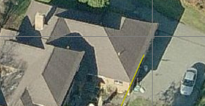
This function allows the operator to import an oblique aerial image and by placing the 3D cursor on a corner, typically an eave corner and aligning the X,Y,Z axes to the image, the pitch of the hip or gable end can be determined. The resultant pitch may be used to create a 2D model or a 3D model of your roof.
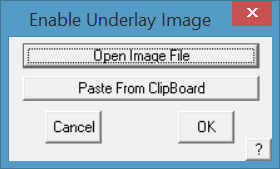
First, import the image. To do this select the Construct Roof > Track Outline function; and select the [Enable Underlay Image] button (refer below for more detail) to place the image on screen from a file (usually saved into the …\Roof Wizard\User folder) or from the image captured in the Windows clipboard using the Windows utility ‘Snipping Tool’ or something similar.
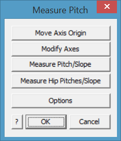
Then select the Measure Pitch tool button. The following dialog box is displayed and the 3D axis icon is placed at the model origin.

Typically the 3 axis indicator comes on screen at an apparent random location (in fact at the work space origin (X,Y,Z = 0), which may not match the current image).
The button [Move Axis Origin] places the 3D axis icon on the desired corner of the roof, typically at an eave corner.
The [Modify Axes] aligns the respective axes with the roof edges in the image.
You can re-do this iteratively until you are happy with the placement. Right click [Cancel] to finish placement.
Measure Pitch/Slope
Next, select the measurement option that suits your job. The [Measure Pitch/Slope] options measure an angle in the selected construction plane or CPL as indicated by the axis indicators set under [Options] described below.
Next you will need to align each axis with an ‘edge’ in the image. Use the [Modify Axes] button, you will be prompted to locate each axis is turn, X, Y and Z to align the axis indicators with the view of the roof.
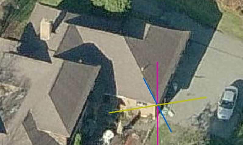
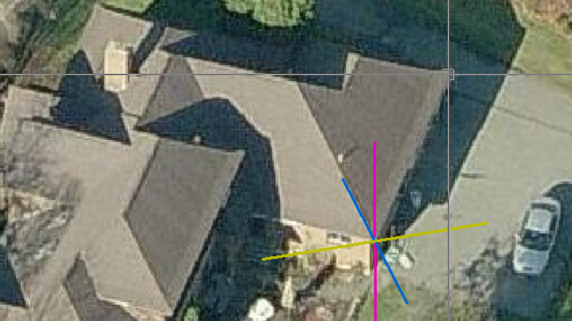
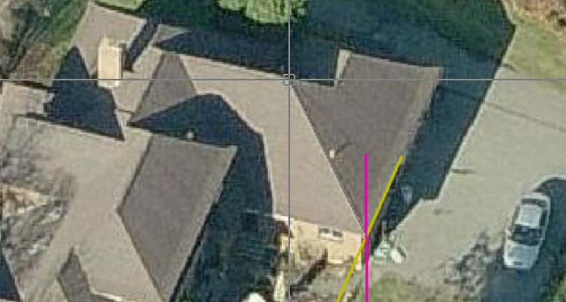
This function would typically be used to measure the pitch or slope of a gable roof as shown below.
- Move Axis Origin (to align with a corner of the roof)
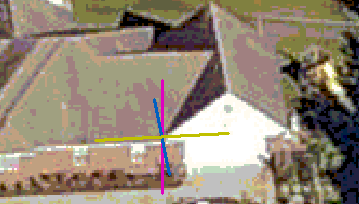
- Modify Axes (to align with image of the roof.
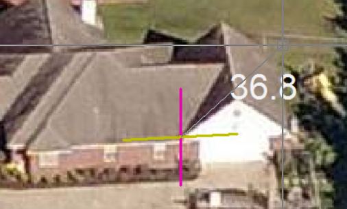
- Measure Pitch/Slope, select plane to measure pitch in (Typically XZ) and click a point in the line of the gable to measure the pitch (here the pitch is shown in degrees). You may also use slope.
If the pitch text is too small or difficult to read, use the [Options] button to chage colour and size of text. You may also change the size and colour of the individual axes as well, so as to make the information easier to read.
Measure Pitch Options
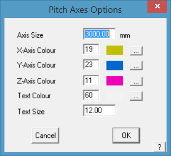
Axis Size sets the size of the lines on sceen representing the X,Y,Z axes.
Axis Colour sets the colour of each axis line from the CAD colour pallet.
Text Colour sets the colour of the text for the pitch dimension. Select a colour that contracts well with the underlay image.
Text Size sets the size of the text on screen, select a number that is large enough to read clearly.
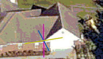
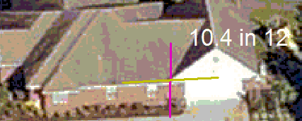
Measure Hip Pitches/Slopes
The Measure Hip Pitches/Slopes prompts for the other end of the hip from the 3D Axes origin, then the apex point of the hip. The hip end is drawn and the pitch of each plane displayed.
This function can be used to measure the pitch of hips and gables.
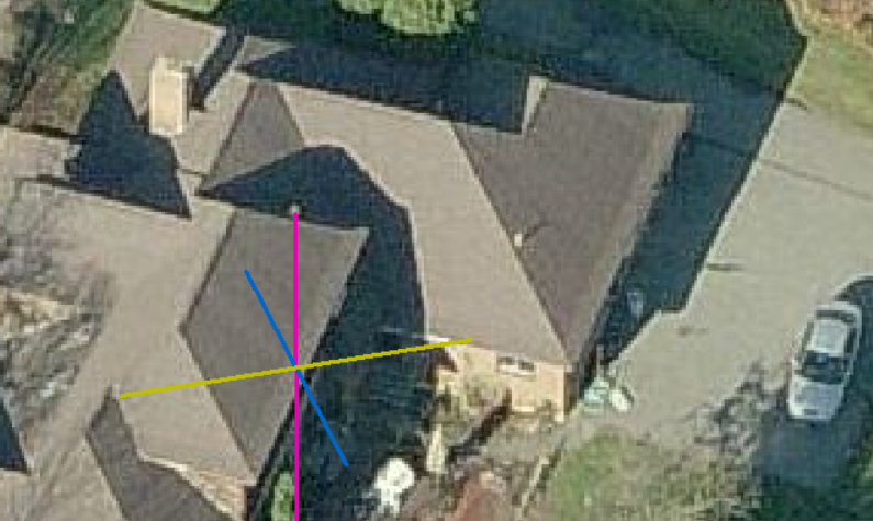
Placement of the 3D Axes origin point with [Move Axis Origin] button.
Left click on the corner of the hip to locate the position of the new axes origin. Align to image with [Modify Axes] button and you will be prompted for the new X axis, new Y axis and new Z axis (read the prompts).
New X axis
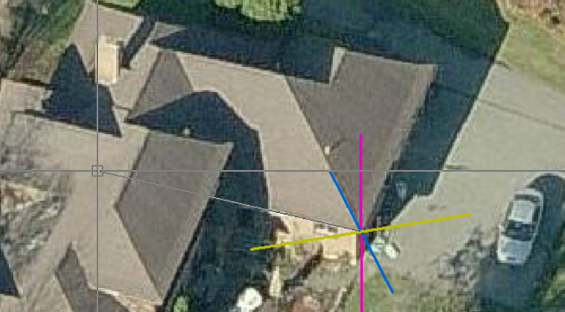
New Y axis, and the new Z axis will usually be in the line of the current Z, straight up the screen. This may vary slightly depending on the image.
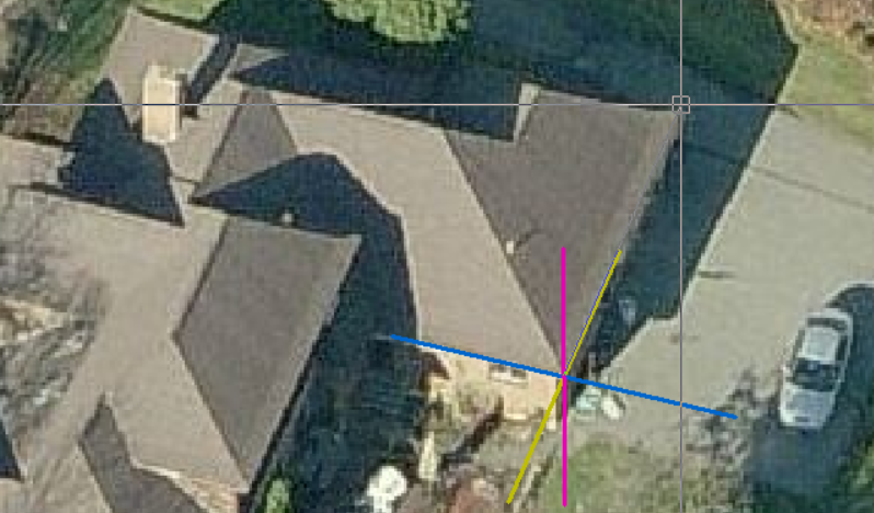
Now select Measure Pitches/Slope and read the propmpts. You will be prompted for the Reference Axis (Base of Hip). Then the axis to measure pitch towards (usually Z axis).
Then indicate the other end of the hip end.
And next the approximate hip apex point.
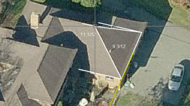
The hip is drawn and the pitches displayed.You may reselect the apex repeatedly to improve the accuracy.
The result will be in degrees, slope or percentage as set in the Set-Up > System Preferences.
![]() Calc Adjacent Pitch
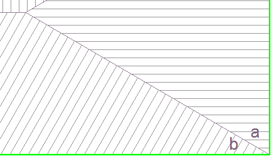
Calc Adjacent Pitch
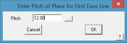
The operator is prompted to indicate pitch of roof plane ‘a’ and digitises the eave lines and the software calculates the pitch of ‘b’.
Distance b/t (between) 2 points
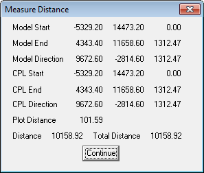
This command reports the distance between 2 points you locate, typically with the middle mouse button so that you are ‘snapping’ exactly to the point.
The dialog displays the Model coordinates with respect to the Absolute origin and the construction plane (CPL) coordinates with respect to the CPL origin. For roofing, this will usually be the same origin as we have no need to change origins. The display shows the coordinates in X, Y and Z. It also shows the distance in each axis between the two points selected. This is a very handy command to use to measure the relative eave heights on two parts of the roof.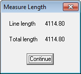
Entity Length
This command reports the length of a line or arc you select. The precision [number of decimal places] for measure length is determined by the defaults set in the CAD program – CAD > Defaults > Systems Settings > Configure.
Sum of Lengths
This command reports the length of a group of lines and arcs you select. You may use this to check the total length of an eave around a roof. The command aggregates the eave line lengths.
Area
This command reports the area of a plane (for example a roof or wall plane) you select.
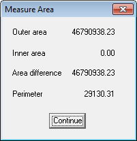
Area and Perimeter
This command reports the area of a closed boundary you select. The command requires you to select the first line and then the successive list of connected lines is automatically traced. (ie instead of selecting a plane, you can select the lines that form the plane boundary).
Area b/t Points
This command reports the area of a shape you have digitised. In this case, you digitise a series of points which define the corners of the shape, typically using the middle button so that you ‘snap’ exactly to the required point.
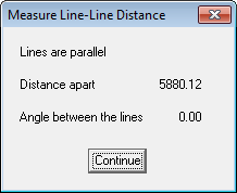
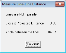
Distance b/t Parallel Lines
This command reports the distance between two lines if they are parallel and the angle between if they are not.
Angle
This command lets you measure the angle given 3 points. Select the points using the middle mouse ‘snap’ feature to ensure that you are EXACTLY on the line end point.
Bearing
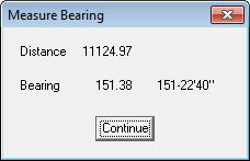
This command lets you measure the bearing given 2 points relative to North (up the page) and also the distance between the two points.
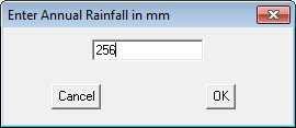
Rainfall Capture
(Pulldown Only)
[Tools > Measure > Rainfall Capture]
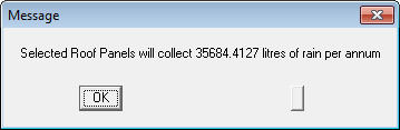
This command provides the ability to determine the amount of rainfall that may be captured from the roof based on average, or specific rainfall. You select the roof planes that will contribute to the catchment and the rainfall for the period, say 240mm in a year – these planes are highlighted, then confirm your selection and then input the rainfall for the period in mm or inches depending on your units defined under preferences. If you wish to calculate rainfall for a shorter period, simply input the rainfall for that period. The result will be displayed as shown below.
Mass Calculations
(Pulldown Only)
[Tools > Measure > Mass Calculations]
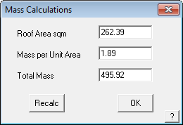
This command allows you to calculate the mass for the roof based on the roof area and a mass per unit area.
Comments are closed.