Report Templates – MS Word
Report Templates – Microsoft Word
Objective: To design or customize the report templates to suit your individual needs.
![]()
Note: This section may appear to be quite a daunting process at first as it requires use of some CAD functions. We suggest you are very familiar with the workings of the software before returning back to this point.
There are two distinctly separate processes for creating report templates from AppliCad software. The CAD template (what we have used for 25 years and still support), and the seamless integration with MS Word or MS Excel for report generation.
When output reports are created by the software, it first looks for a Microsoft Word template of the required name form, for example QuotationLetter. The file it is looking for must be saved in the ..\User folder or ..\Corporate and must have the name of QuotationLetter.DOC without spaces as a Word Document or QuotationLetter.DOT as a regular Word Template document.
The file format must be Microsoft Office 1997 – 2003 compatible – that is, no XLTS or DOCX formats. This ensures backwards compatibility for all users.
If the software finds the DOC or DOT by the defined name, it will use it. If it does not find a Microsoft Word template, it will use the AppliCad default CAD template for QuotationLetter which is saved in the AppliCad database file, RoofWiz.dab. This will ensure that all your existing default CAD templates will work as they do now when the software is updated by new releases.
Creating a template in MS Word allows for more creativity in design and many operators may be more familiar with Microsoft Word than the CAD functions. The use of Word Templates is described later in this section. Using a Word template, you can have as much or as little information as you require for your projects. If you plan to use Word templates exclusively, you might consider going direstly to that section below, however, a lot of useful information is described in the CAD template section.
Setting Up MS Word as your Report Generator
This section describes the use of Microsoft Word/Excel to create templates. It is not a Microsoft Word/Excel tutorial – it assumes moderate to high level of competency in the use of Word/Excel.
The first thing to understand is that the software will use the default report templates created in the CAD software if no Word or Excel template exists. This is necessary to ensure that existing operators can continue their use of the software without interruption because of a new reporting template options.
At any stage you may decide to use Word or Excel as your template editor and if the software finds a Word or Excel template, that template is used INSTEAD of the default CAD template. Over time, we believe that the MS Word template will be the preferred option because of the greater flexibility of the design elements that it affords the user.
The standard CAD template names will be maintained throughout as described below:
| Report name | Template name | Intended Use |
| Quotation letter | QuotationLetter | A quotation to send to your customer detailing the information as a letter |
| Quotation form | QuotationForm | A quotation to send to your customer detailing the information in a tabular fashion. |
| Quotation acceptance | QuotationAcceptance | Same as above with the addition of a place for the customer to accept the quote with a signature |
| Quotation details | QuotationDetails | This report tabulates the materials and costs for the job |
| Installer pay summary | PaySummary | This report tabulates the labor costs for you to perhaps give to the installer |
| Material cutting list | MaterialCuttingList | This report tabulates the sheet and flashing cutting lists |
| User form 1 | UserForm1 | An extra form for you to define |
| User form 2 | UserForm2 | An extra form for you to define |
| User form 3 | UserForm3 | An extra form for you to define |
| User form 4 | UserForm4 | An extra form for you to define |
| Order Forms | OrderForm | The Supplier’s Order form. Generated for each supplier in your list of required items. |
| Tax invoice 1 | TaxInvoice1 | A tax invoice |
| Tax invoice 2 | TaxInvoice2 | A tax invoice |
| Bill Of Quantities | BillOfQuantities | A Bill Of Quantities report |
| Roof Quantities | Roof Quantities | Summary of roof geometry (areas and lengths) and a roof plan |
The important difference in the process is that you create a report template using Microsoft Word or Microsoft Excel that suits your needs. You will save it as a Word template or Word document and use the default CAD template name and that will be used instead.
That is, QuotationDetails will be saved as QuotationDetails.DOT (Word template file) or QuotationDetails.DOC (Word document file), without spaces; QuotationLetter will be QuotationLetter.DOT etc. If created in Excel they will be saved as QuotationDetails.XLT (Excel template file), or QuotationDetails.XLS (Excel spreadsheet file).
These files must be saved in the …\User folder for local use or the …\Corporate folder for wider company use. The file format must be Microsoft Office 1997 – 2003 compatible – that is, no XLTS or DOCX formats. This ensures backwards compatibility for all users.
Linking Templates to Output
You can however create any other report template with any name so long as these names are listed in the text files called UserReportNames.csv and UserDrawingNames.csv . The software needs to know that you have created a new template, what it’s called, and how you wish to refer to it.
UserReportNames.csv is where the preset template names for CAD and Word/Excel Report Templates are associated with the reporting output process.. This allows any template form/report to have any name when displayed in the print options list. Column A is the name you wish to have in the [Print] options list. Column B is the actual file name in the ..\User folder when viewed in Excel.
UserDrawingNames.csv is where the preset template names for both CAD and Word/Excel Drawing Templates are associated with the drawing output process. This allows any template form to have any name when displayed in the print options list. Column A is the name you wish to have in the Print options list. Column B is the actual file name in the ..\User folder. For drawing output as distinct from report output, you need to tell the software what sort of drawing it is so that th ecorrect information is automatically included, without you having to do any further work in generating the report. This is done in column C using the code number as required.
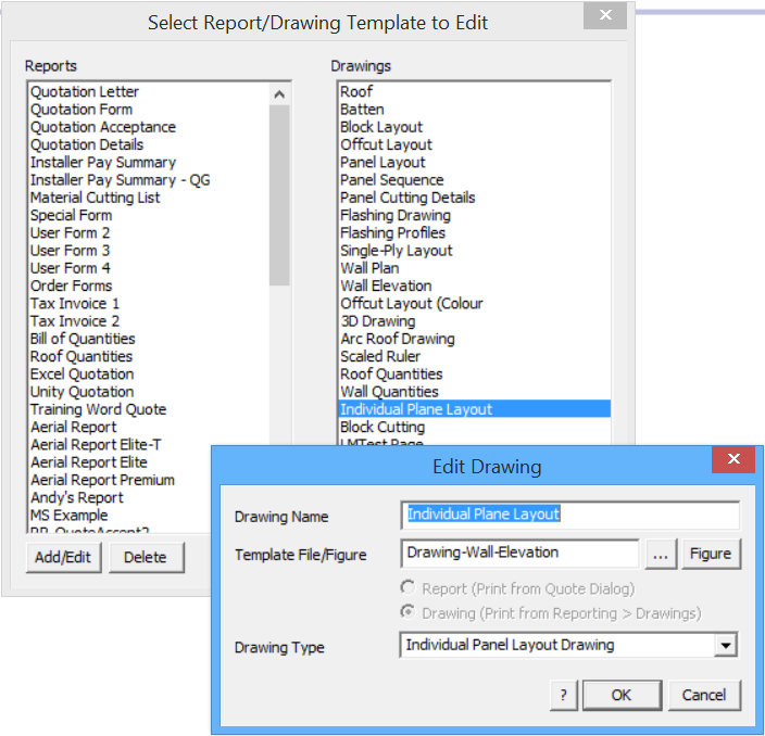
Once a new template has been created, and saved to the …\User folder, it can be added by simply going to the Tools > More > Edit User Templates option.
The complete list of both CAD templates and Word/Excel templates is displayed.
To add your new Word template to the list, select Add/Edit and the Edit Report dialog is displayed that provides for you to add the new report name (as you want it to appear in your print options list) and then select the name of the actual template file (for Word or Excel) or subfigure name (if it is a CAD template).
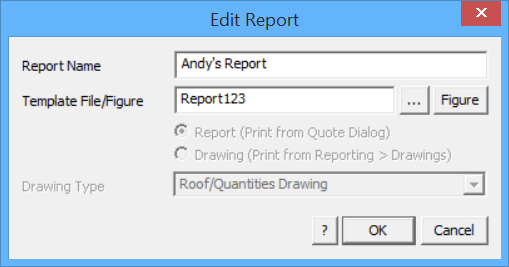
Select [OK] and the new report template is linked and available in your print list. If it is a drawing template, the extra option is displayed to set what type of drawing output you require.
Designing your Own Templates
The process that the software uses with either AppliCad CAD templates or Word/Excel templates is the same – we use regular text and what we call Key Text Strings (KTS). The illustration below shows the different application of the two types of text – ‘Date’ is regular text; ‘###Date’ is a Key Text String.
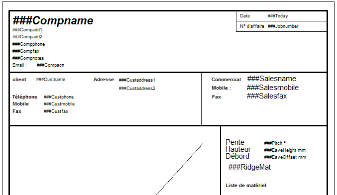
Regular or normal text – no ### signs Key Text String – with ### signs
The first thing you must do is decide what needs to be on your report. The starting point for that would be what you currently use to supply a proposal to your client. Look at the content and the layout. Consider what works now and what has been deficient in the past. Use this opportunity to revamp your proposals.
Now decide what is ‘regular text’ and type this onto your Microsoft Word/Excel document using the layout and composition functions of MS Word.
Next type in the Key Text String for the variable you need the software to insert when it creates the output report. There are 100’s of key text strings variables for you to use.
Note that Word templates allows the use of Headers and Footers and multiple graphics files such as logo’s etc. The best layout will come after some experimentation, so try all the options that come to your mind.
A complete list of all Key Text Strings is here.
The same process with templates is used to define the templates for the various roof drawings that typically form part of the client’s proposal. These are listed below:
| Drawing name | Template name | Intended Use |
| Roof drawing | Drawing-Roof | Shows the roof |
| Batten drawing | Drawing-Batten | Shows the battens on the roof |
| Block Layout | Drawing-block | Shows the blocks on the roof as created by Auto-Block |
| Offcut Layout | Drawing-offcut | Shows the cuts and offcuts created by Gen-OffCuts |
| Offcut Layout (Colour) | Drawing-offcut-colour | Shows the cuts and offcuts created by Gen-OffCuts using coloured planes that aid in offcut placement. |
| Panel Layout | Drawing-sheet | Shows the sheets on the roof as created by Gen-Sheets |
| Panel Sequence | Drawing-Sheet-Sequence | Shows the sequencing of panel cutting derived from Linear nesting |
| Panel Cutting Details | Drawing-Sheet-Cutting | Shows the detailed dimensioned panels |
| Flashing Drawing | Drawing-flashing | Shows the roof and dimensions for each roof line as detailed by Dimension-Roof Lengths |
| Flashing Profiles | Drawing-Flashing-Profile | Details the workshop drawings for the fabrication of custom flashing profiles |
| Single-Ply Layout | Drawing-SinglePly | Shows the membrane layout generated by Cover Select-Membrane Layout-SinglePly |
| Wall Plan | Drawing-Wall-Plan | Shows the wall layout |
| Wall Elevations | Drawing-Wall-Elevation | Shows an elevation drawing of each wall |
| Arc Roof Production Drgs | Cranking.DAB | Details the workshop drawing for the fabrication of cranked panels |
| 3D Design Drawing | Drawing-3D | ISOmetric view of roof in 3D |
| Scaled Ruler | Scaled Ruler | A drawing that allows you to scale from drawings with unusual scale factors. |
| Individual Plane Layout | Drawing-Wall-Elevation | Prints each roof plane and its panel layout (using the wall plane template) |
| Block Cutting | Drawing-BlockCutting | The block-cut details layout drawing |
![]()
Note: It will also help you a lot to preview AppliCad’s standard report templates as described above before you edit or design your own, especially the roof drawing reports as they do have particular needs that will become apparent upon review.
There is a significant difference between the AppliCad default CAD template and the Word template and that is with the placement of the thumbnail of the roof plan into the report. To get the roof plan (with or without dimensions) into the Word report, you must create a ‘text box’, a ‘shape’ or a ‘table’ in Word, and add the Key Text String for the required roof drawing, such as ###RoofDrawing into the shape, table or text box.
Before the roof plan is inserted into the report, AppliCad creates a separate file of the roof drawing called RoofDrawing.eps (a postscript vector format print file) based on the current view of the 3D model, that is at the time you go to the Reporting > Supply and Install screen, and select [Print].
This is fundamentally different to the way the roof drawing is placed using the CAD report when it is generated from the CAD template.
Refer below for more options with inserting the roof drawing into a MS Word template.
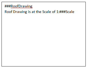
The Text Box essentially defines the extents of the roof drawing on your template. If you wish to constrain the roof drawing to a particular scale (so that you may actually check measurements from it, you insert the Key Text String for the scale) controlled as required by the process described below.
If the scale of the roof drawing is not relevant and you simply require the largest possible drawing, use the key text ###UnscaledRoofDrawing and the roof drawing will be placed inside and constrained by the text box or cell, The roof drawing will maintain its aspect ratio.
Scaling the Roof Picture
Any CAD report or CAD drawing that incorporates a picture of the roof, draws the roof to best fit between the extents of the diagonal line input on the template on layer 999. Refer to the section of the manual dealing with defining CAD templates. The roof picture may be further constrained by a ‘proper’ scale factor so that the picture may be compared with other drawings of known scale. For example the best fit across the page might be 1:187. This cannot be compared to anything useful, so the software automatically adjusts this scale to 1:200 if that is one of the scale options that you have set.
The range of scale options is defined in the software and these scales are 10; 20; 50;100; 125; 150; 175; and 200.
The operator may also define any other scale options. This is done by defining a series of scale values in a simple text file. The file must be called Scales.dat; it must be in the ..\User folder and be in the form of:
50
100
115
125
150
165
175
200
END
The word END at the bottom of the list is essential for it to work properly.
You may also have the roof picture included totally within the entire text box at what would essentially be a random scale and for this you use the Key Text String of ###UnscaledRoofDrawing.
Managing Content of Report Images
For all standard reports the ###RoofDrawing will usually be sufficient. However, with new developments, the operator can now control the appearance of the attributes of the roof as they appear on the report using ###RoofImage[n].
The key text string for this option allows the operator to control the level of annotation applied to the roof drawing. For example, you might require dimensions, roof slope/pitch and Line types. This can be achieved by setting the ‘switches’ as shown below, in the combination that you require for the desired output.
The following list summarises what is included on the drawing of the roof model.
Additional annotation Switch
 1 -  Roof planes (1 = on, 0 = off)
 2 -  Display Walls (2 = on, 0 = off)
 4 -  Panel layout/Block layout/Offcut layout (4 = on, 0 = off)
 8 -  Dimensions (8 = on, 0 = off)
 16 - Roof Pitch/Slope (16 = on, 0 = off)
 32 - Line type (32 = on, 0 = off)
 64 - Flashing annotations (64 = on, 0 = off)
 128 - Battens/Purlins (128 = on, 0 = off)
 256 - Course lines (256 = on, 0 = off)
 1024 - Section Details Report (1024 = on, 0 = off)
 2048 - Block-Cutting (2048 = on, 0 = off)
 4096 - Roof plane areas (4096 = on, 0 = off)
 8192 - Display defined Zones (8192 = on, 0 = off)
To get the desired combination you add the value of the switches together. So if you wanted to reproduce a roof drawing on your report that included pitch and dimensions n=8+16=24, and your key text string would be ###RoofImage[24].
For flashing annotation and downpipes on the same roof drawing, n=64+512=576 and the key text would be ###RoofImage[576].
In the example below we have roof planes, walls, panel layout, dimensions, downpipes you would need n=1+2+4+8+128+215 = 675 – ###RoofImage[675]
RoofImage[675]
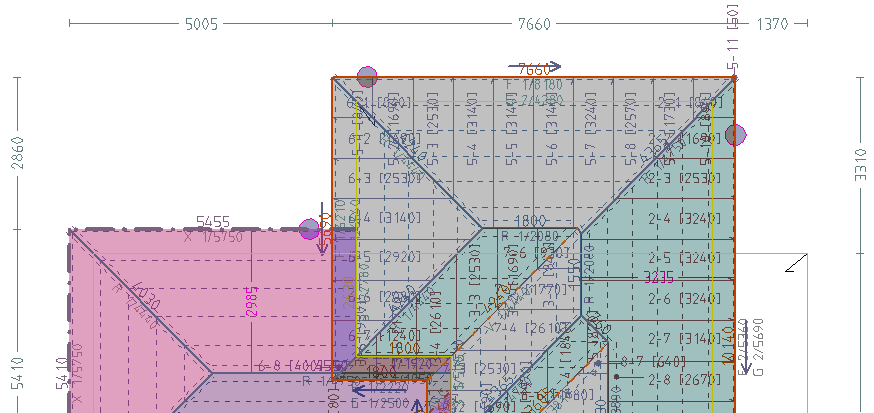
All the required information must already have been placed on the 3D model, and this would normally be the case during the development of your job.
The exception to this are pitches/slopes and linetypes, as these are normally not left with the model, they typically only used during checking. If they are not in the model and you select them for the report, they will be added for you before it processes the key text string.
This provides a lot of additional control over the appearance of your reports and the level of detail you wish to provide your customers and installers. You can go simple with ###RoofDrawing or complex with ###RoofImage or ###RoofImageC – the ‘C’ denotes constrained as it will not auto-rotate.
Before the roof plan is inserted into the report usng ###RoofImage(n), AppliCad creates a separate file of the roof drawing called RoofImage.TIF (a bitmap image file) based on the current view of the 3D model, that is at the time you select the Reporting > Supply+Install screen, and select [Print].
![]() If you want a plan view, have plan view displayed. If you want perspective or ISO view, select those views BEFORE you select Reporting > Supply+Install.
If you want a plan view, have plan view displayed. If you want perspective or ISO view, select those views BEFORE you select Reporting > Supply+Install.
WallImage[n] works in the same way for creating wall reports. the operator can now control the appearance of the attributes of the wall as they appear on the report using ###WallImage[n] where n = the ‘switches’ as shown below, in the combination that you require for the desired output, in the same manner as described above for the roof report.
1 – Display the Wall Plane Shading (1 = On, 0 = Off)
2 – Display Wall Panels (2 = On, 0 = Off);
4 – Display the Wall Dimensions (4 = On, 0 = Off)
8 – Display the Wall Line Types (8 = On, 0 = Off)
16 – Display Flashing Annotation (16 = On, 0 = Off)
32 – Display Wall Battens/Purlins (32 = On, 0 = Off)
64 – Display Wall Section Details (Reserved for Later Use)
128 – Display Wall Plane Areas  (128 = On, 0 = Off)
256 – Display Overall Dimensions (Reserved for Later Use)
512 – Display Automated Wall Plane Labels (512 = On, 0 = Off)
1024 – Display Automated Wall Plane Labels including Windows & Doors (1024 = On, 0 = Off)
2048 - Display Automated Window & Door Labels Only (2048 = On, 0 = Off)
Auto-Rotate View
The program utility that combines the various roof drawings with the Word report template looks at the style the target document and will perform additional functions as required. It only works with Word templates. The view of the roof may be inserted into the Word design elements of table, text box or shape.
The key text ###RoofDrawing will scale as required, but will not rotate the model image. It will be auto-scaled to the size of the shape or text box unless otherwise controlled as described in the preceding section.
If you decide to place a table element into the Word template to define the placement of your drawing detail you must set the height AND width of the table cell to suit your template design. All drawing types (other than ###RoofDrawing), such as ISORoofDRawing, sheet layout or flashing layout etc, the software will auto-scale and auto-rotate to best fit the extents of the defined cell.
If you use Word design elements such as shapes (typically rectangular) or a text-box, the drawing will auto-scale, but NOT auto-rotate. These are limitations of MS Word and not anything AppliCad can control.
Inserting Bitmap Images
A further option exists to place bitmap images into the report. These may be constrained to the original proportions of the image or adjusted to fit the text box it is inserted into. The images must be saved in the operator’s \User folder and be of a prescribed name that matches the name used in the template.
We may also place selected image files into a report template. For example, as shown below we have a place marker in the text box for two images ###Image[East.jpg] and ###Image[West.jpg]. The appropriately named images from the …\User folder will be automatically inserted to fully fit the size of the text box adjusting the proportions to fit the space. This may distort some image files and should be taken into account.
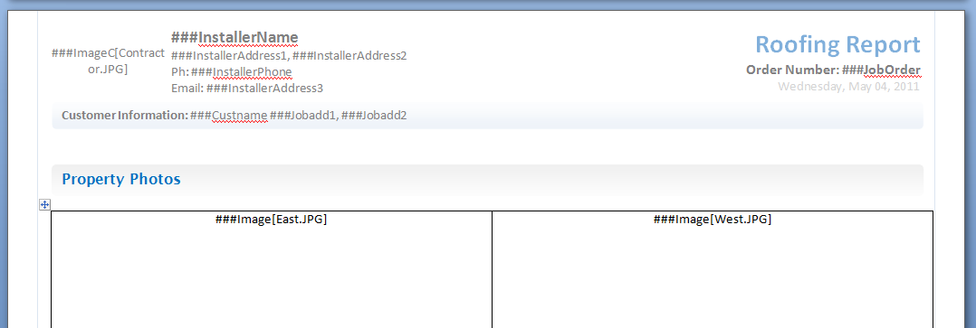
Using the key text ###ImageC[filename] – the letter C designates that the image is to be constrained to the original proportions. This is important for dimensioned roof drawings.
This may also be used to place customer logo’s and other fixed size graphics into a report – such as Contractor.jpg is the contractor customer logo. This bitmap image must also be saved in the …\User folder and have a fixed prescribed name.
Images and drawings may also be placed in the header and/or footer of the Word template.
A quick and convenient way to insert images of your roof model or plan drawing into any document is to capture them from the screen using the Tools > Export Image from Screen function.
The first thing to do is set up the model on screen to display precisely what you wish to see in the report. A good example might be the 3D Isometric view (although a ket text string will do this automatically).
Then select the command – Tools > Export Image from Screen. You will be prompted for a file name. This should be the same name that you have used in the creation of the template – for example, 3D-Iso-View.jpg.
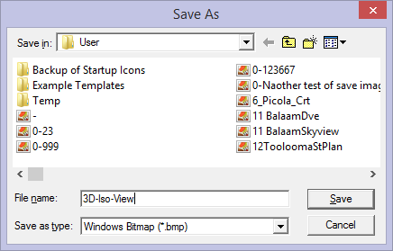
Select [Save] and a bitmap file is saved to the …\User folder. Your template should be created with the appropriate key text string to automatically transfer this exact image to the report.
In this example, the key text would be ###ImageC[3D-Iso-View.jpg]. When the report is run, the image will be collected by the program and placed into the Word template for you. You can create as many of these as you need to illustrate your reports. The name of the file must match the name used in the key text.
![]() Note – the program will go off and find any file with the name specified in the …\User folder. If you forgot to create one for the the current job, or you didn’t need that particular view, the software will still go looking for the file (because it is in the template) and if it finds one, even though it may be from a different job, it will still insert it into the report.
Note – the program will go off and find any file with the name specified in the …\User folder. If you forgot to create one for the the current job, or you didn’t need that particular view, the software will still go looking for the file (because it is in the template) and if it finds one, even though it may be from a different job, it will still insert it into the report.
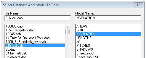
To place other details into the report automatically, you can create models in the job database that contain the required information, such as a pitch diagram or roof azimuth diagram. Once the information is inserted on the roof model it must be saved with a model name that describes what the model is displaying. The standard options are summarised below:
| Model Name | Displayed information | AppliCad Function |
| AREAS | Roof area dimensions | Tools > Dimension > Roof Plane Areas |
| GRID | Planning GRID | Render > Insert Roof Grid |
| AZIMUTH * | Azimuth of roof planes | Tools > Diemsion > Insert Roof Azimuth |
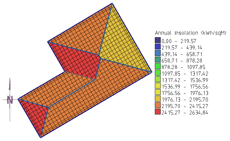
| INSOLATION * | Solar radiation map | Render > Generate Insolation Map |
| LENGTHS | Lengths of roof features | Tools > Dimension > Insert Roof Lengths |
| PITCHES | Pitch of each roof plane | Tools > Show Pitches |
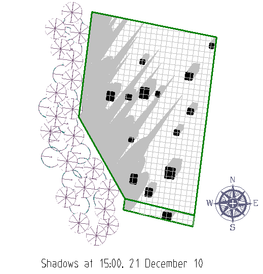
| SHADOWS * | Shadow map | Render > Generate Insolation Map (shadow palette) |
* Available options, only if you have the AppliCad Solar Wizard module installed
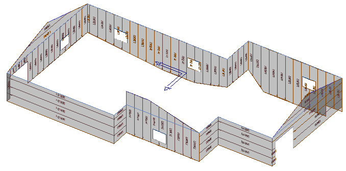
The various models defined during the process of modelling the job are converted to an EPS format file by the AppliCad software, Word is opened automatically and the EPS file placed into the report by the program. Microsoft Word/Excel must be installed on the computer where the reports are to be generated.
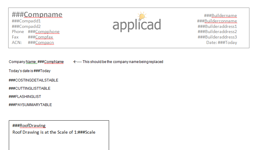
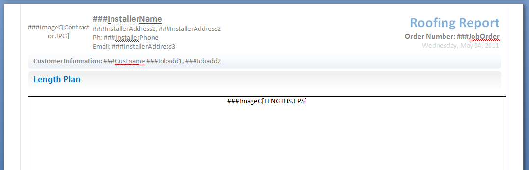
Below shows an example of the MS Word/Excel template showing the key text string for adding the LENGTHS model data into the report. Use the same process for adding any of this model data to a report.

Complete a report template with details such as a GRID diagram or shadow map or an insolation map (only if you have AppliCad’s Solar Wizard modules installed).
![]() Note: For those people designing forms for use with foreign languages, regular text can be in whatever language you use, but Key Text Strings MUST be exactly as defined by AppliCad; as shown in the example in the previous page.
Note: For those people designing forms for use with foreign languages, regular text can be in whatever language you use, but Key Text Strings MUST be exactly as defined by AppliCad; as shown in the example in the previous page.
How it All Works
A report template may be a Word DOC or a Word template; an Excel XLS or an Excel template. If a Word/Excel document template exists in the user folder, say QuotationLetter.DOC designed by the operator to suit the needs of the business, the AppliCad software will use this template as the basis of the report instead of the default AppliCad CAD template.
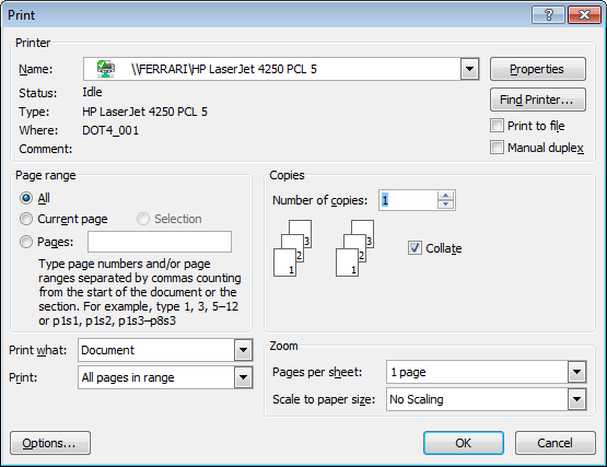
When you select Print from the Supply Only dialog or Supply+Install dialog
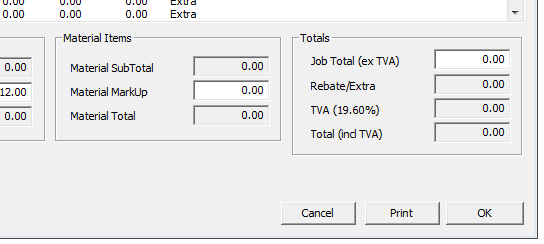
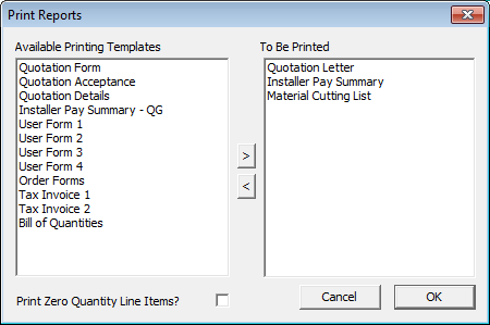
The process pulls up the list of report options. The list or reports available is on the left hand side of the box and to move the required reports to print, double click it or select it and then click the [>] arrow button.
Select [OK] and the process begins. Depending on the settings in the System Preferences you have set Microsoft Word will be displayed and show the form being completed and a print dialog may also displayed, providing the opportunity to select one of your network printers.
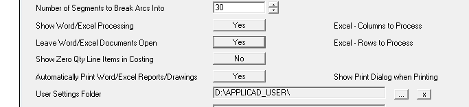
Part of the Preferences dialog where you set the printer and display options for showing what Word is doing as it does it.
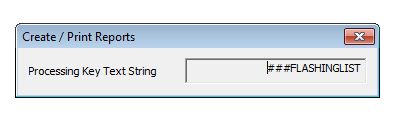
As each variable is determined by the software, the progress is also displayed in a dialog on the AppliCad screen. This confirms that the process is working correctly.
Once the report has been created, you are prompted to select the printer to print to, or it automatically prints to your default printer.
If the report subsequently consists of multiple pages they will all print one after the other.
At the same time a Word/Excel document is created that may be reviewed and or modified and reprinted at any time. The Word/Excel document is created with a name that consists of the AppliCad file name, a dash then the AppliCad model name in that file and another dash, then the form name for example QuotationLetter.
So a job saved in AppliCad as BillsRoofing.DAB and the job is called 12HighStreet, the Word document will be called – BillsRoofing-12HighStreet-QuotationLetter.DOC.
It will be saved to the ..\User folder.
![]() Note – In general, MS Word processes the key text strings by first searching the document, then headers and footers, then text boxes and lastly shapes. As it encounters each key text string, the substitution of the real value is made. You can observe this if you have Word open when you run the report prior to printing
Note – In general, MS Word processes the key text strings by first searching the document, then headers and footers, then text boxes and lastly shapes. As it encounters each key text string, the substitution of the real value is made. You can observe this if you have Word open when you run the report prior to printing
.
Word Table Formats
Microsoft Word has an amazing set of tools for creating and using tables and AppliCad makes use of this capability to allow you to custom design the appearance of tables in your AppliCad output.
If you do nothing, the tables will be presented using the default settings AppliCad has defined, however you are not constrained by these settings. You can create a text file that presets the appearance of the table in your Word document. This file is called tableformats.csv and may be edited to better suit your specific needs.
Since it is a CSV file (comma separated values format file), it may be edited in Wordpad, or preferably Microsoft Excel.
It is in the form as shown below:
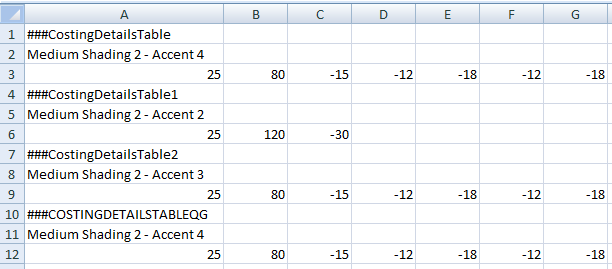
Required Table Layout
The first line is the name of the table. The second line is the name of the Microsoft Word pre-defined table appearance and format found in Microsoft Word under Table Tools > Design. Refer to Microsoft Word Help for more details on how to select these options. The third line is the width of each column in the table in millimetres. A negative width indicates that the content of the cell in the column must be right justified as you would wish to see currency displayed.
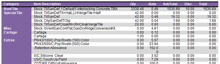
In the example below, the costing details table is displayed using the Word format called Medium Shading 2 – Accent 4. The columns are the widths as shown above (line 3 of our spreadsheet) and the numbers in the columns are right justified.
The roof drawing is also completed at this time with annotation that shows the adjusted scale of the roof picture.
User Defined Report/Drawing Names
All the standard reports and drawings may be modified to suit the requirements of your business. This includes adding new reports using an existing template structure or to simply changing the name of a report or drawing as it appears in the list of operator options.
This is achieved by creating a translation or lookup file that defines the structure of the report/drawing and its name. There are two files – UserReportNames.csv and UserDrawingNames.csv. Being a CSV file format, they may be edited in Microsoft Excel or Notepad. The form of this file is as shown below:
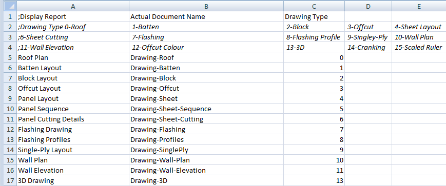
UserDrawingNames.csv
| Display Report | Actual Document Name | Drawing Type |
| ;Drawing Type 0-Roof, 1-Batten, 2-Block, 3-Offcut, 4-Sheet Layout, 5-Sheet Sequence, ;6-Sheet Cutting, 7-Flashing, 8-Flashing Profile, 9-Singley-Ply, 10-Wall Plan ;11-Wall Elevation, 12-Offcut Colour, 13-3D, 14-Cranking, 15-Scaled Ruler, 16-Individual Panel Layout, ;17-Block Cutting Layout, 18-Aerial Imagery Report |
||
| Roof | Drawing-Roof | 0 |
| Batten | Drawing-Batten | 1 |
| Block Layout | Drawing-Block | 2 |
| Offcut Layout | Drawing-Offcut | 3 |
| Panel Layout | Drawing-Sheet | 4 |
| Panel Sequence | Drawing-Sheet-Sequence | 5 |
| Panel Cutting Details | Drawing-Sheet-Cutting | 6 |
| Flashing Drawing | Drawing-Flashing | 7 |
| Flashing Profiles | Drawing-Flashing-Profile | 8 |
| Single-Ply Layout | Drawing-SinglePly | 9 |
| Wall Plan | Drawing-Wall-Plan | 10 |
| Wall Elevation | Drawing-Wall-Elevation | 11 |
| Offcut Layout (Colour | Drawing-Offcut-Colour | 12 |
| 3D Drawing | Drawing-3D | 13 |
| Arc Roof Drawing | Cranking-Drawing | 14 |
| Scaled Ruler | Scaled-Ruler | 15 |
| Individual Panel Layout | Drawing-Panel-Layout | 16 |
| Block Cutting Layout | Drawing-Block-Cut | 17 |
| Aerial Measurement Report | Drawing-Aerial-Report | 18 |
| Roof Sketch Pad [L] | Sketch-Pad-Letter | 0 |
| Roof Sketch Pad [A4] | Sketch-Pad-A4 | 0 |
In the case of the Drawing Reports, the form of these is more strictly controlled and the output style is determined by the information that is inserted on the form automatically by the software. For this reason, the drawing type must also be specified so that the required details for that drawing style are added.
Regular reports and drawing reports may be given any name that suits you, simply by editing the csv file. For example, a generic template called UserForm1 can be renamed in the table as Special Form 1 and that is the name that will appear in the list for selection for processing.
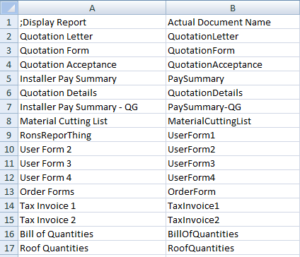
UserReportNames.csv
| ;Display Report | Actual Document Name | |
| Quotation Letter | QuotationLetter | |
| Quotation Form | QuotationForm | |
| Quotation Acceptance | QuotationAcceptance | |
| Quotation Details | QuotationDetails | |
| Installer Pay Summary | PaySummary | |
| Installer Pay Summary – QG | PaySummary-QG | |
| Material Cutting List | MaterialCuttingList | |
| Special Form | UserForm1 | |
| User Form 2 | UserForm2 | |
| User Form 3 | UserForm3 | |
| User Form 4 | UserForm4 | |
| Order Forms | OrderForm | |
| Tax Invoice 1 | TaxInvoice1 | |
| Tax Invoice 2 | TaxInvoice2 | |
| Bill of Quantities | BillOfQuantities | |
| Roof Quantities | Roof-Quantities | |
Renaming a standard form is simply a matter of changing the name in the UserReportName file.
In each situation the report or drawing template must exist either as a sub-figure in the database RoofWiz.dab (as shown in the example list above) or as a Word template or Excel document of the same name. When the reporting process is run, the software looks for the Word DOC or DOT first (for example QuotationForm.doc) and if it finds a doc or template file, it runs it. If no Word DOC or DOT file is found, then it looks for an Excel XLS or XLT (for example QuotationForm.xls) and finally it searches for the standard CAD form that is the sub-figure in Roofwiz.dab (for example QuotationForm).
![]()
NB – There is one exception to this rule – the MS Word template of the OrderForm must be called ‘OrderFormTemplate.doc’ instead of ‘OrderForm.doc’ for the automatic substitution to take place. The file name reference will still refer to ‘OrderForm’ as shown above.
The process is entirely automatic, provided all the links in the process are there. Work carefully with this and get it right. Do it once and then it will save you hours and hours, over and over as you generate the multitude of report options that you might need to help run your business.
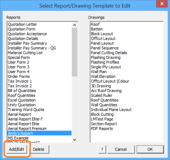
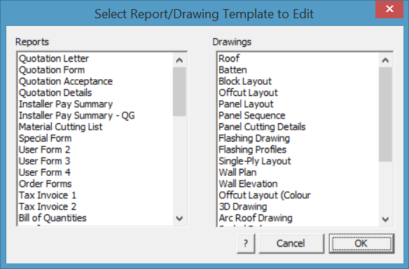
Once defined, the operator selects the command Reporting > Print Drawings and the available drawing options are displayed:
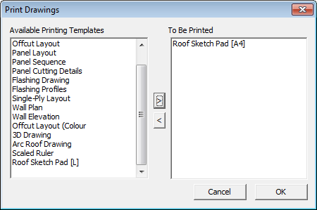
Double click the required drawing to be printed and it is added to the list. Select [OK] and the printing process will begin.
The job reports are generated after the operator selects either Reports > SupplyOnly or Reports > Supply+Install. Once the material list and labour summary have been checked, select the Print button.
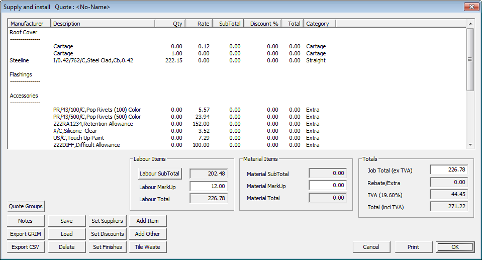
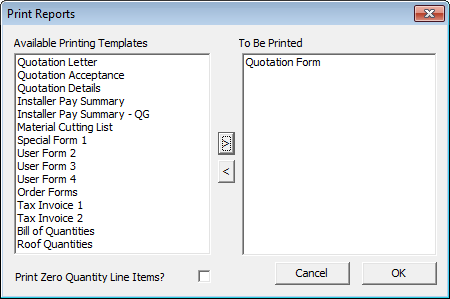
The list of available reports is displayed. Double click the required report and the select [OK] to process the data, generate and print the report.
The combined capability of report and drawing design using AppliCad, Word and Excel allows for extraordinary flexibility in designing custom reports and drawings for all aspects of your business from supplier orders to client proposals.
The page name for each report is placed on the report using the key text ###Title. The software looks for the report temple name, for the report being printed and replaces the key text ###Title with that name eg for Quotation Acceptance report, Quotation Acceptance will go into the report where you inserted ###Title. As has been explained above, these names are stored in the editable text files called UserDrawingNames.csv and UserReportNames.csv.
When creating your own custom reports, perhaps start with one of our standard forms and modify to suit. Make small changes to start with so that you see how the process works. Once you have confidence in what is required and the result that you get, then go hard. Make the reports/forms work for you.
Computing Values Using Line Items
Line items are values generated by the software and displayed in the Reporting > Supply Only or Supply and Install dialog box. Using Line Items is a standard function of the software and is typically used to extract values for your reports based on calculated values using the Line Items where the value will vary with each job and quotation calculation.
For Line Item calculations to be determined in a report by the software for a Word or Excel based report, the key text string for that Line Item must be preceded by two ## signs. This is a variation on the use of the # signs for the AppliCad based reports where three # signs are used. This is to ensure that the right calculation is being used in the right report.
Line Item Key Text Strings for Word/Excel Reports
These text strings mimic the values in the Reporting dialog box. This kind of text string is in the form:
##LI <LineItemCategory>_<subcategory>_<number off>
where <LineitemCategory> is the category you see in the costing dialog
and <subcategory> specific category item
and <Line No> the line number required.
The structure is:
##LI_<Category>_<Sub-Category>_<Line-Number> where the use of the underscore between each element in the key text string is essential.
| Category | Sub-Category | Line-No |
| COVER (roof cover material)
FLASHFITT (flashing or fittings) ACCESS (accessories) FAST (fasteners) SEARCH (anything) |
MAN (supplier)
SUP (supplier) DESC (description) QTY (quantity) RATE (cost rate per item) SUB (sub-total cost) DISC (discount) TOT (total cost) CODE (product code) FULL DESC (product description) FIN (finish) GAUGE (base metal thickness) |
The line number required from the list displayed in the ‘Costing’ screen. |
The syntax for the use of the ##LI_SEARCH function is typically as shown below, used to find an additional freight charge in the list of line items:
Additional Freight Charge $##LI_SEARCH(FRGHT)_Sub_1
Searched for FRGHT anywhere in the list of items under Costing and returns the Sub-Total of the first item.
Example of the use of these strings might be:
| Cover – Product Code | Description | Quantity |
| ##LI_Cover_Code-1
##LI_Cover_Code-2 ##LI_Cover_Code-3 Etc. |
##LI_Cover_Desc-1
##LI_Cover_Desc-2 ##LI_Cover_Desc-3 Etc. |
##LI_Cover_Qty-1
##LI_Cover_Qty-2 ##LI_Cover_Qty-3 Etc. |
| Flashing – Product Code | Description | Quantity |
| ##LI_Flashing_Code-1
##LI_Flashing_Code-2 Etc. |
##LI_Flashing_Desc-1
##LI_Flashing_Desc-2 Etc. |
##LI_Flashing_Qty-1
##LI_Flashing_Qty-2 Etc. |
Inline Calculations with Key Text Strings for Word/Excel Reports
You can embed key text string values into a text string as a calculation.
The format of a calculation string is
%CALC [<expression>]:<precision>
where
%CALC is a key word stating that a calculation exists
[..] the brackets which encompass the expression and precision
<expression> the expression eg 2*###TotalIncTax +100
: a colon separating the expression and the precision
<precision> the number of decimal places you want to display
For example, to add 10% to the total price for a job,
The total price for you is %CALC [###totalinctax + ###totalinctax / 10]:2
If the ###totalinctax amount was 3000, then the amount reported above would be 3300.
![]()
Note: These calculations are also valid if they are included in a Grim Template File too.
Comments are closed.