Project Wall
 Project Wall
This command automatically projects the wall lines in the model down by an amount you enter, to the construction plane or selecting one wall at a time and project that to a specified height. After you select the command, you are prompted to enter the wall height. The default value is the eave height you have entered earlier. The original wall lines are modified to become the top of the wall then are projected down the height you want. Note that the original wall lines are deleted.
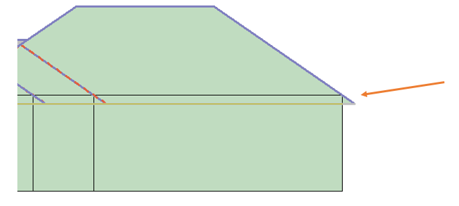
The following diagram shows an elevation view of a roof confirming where the walls are projected from.
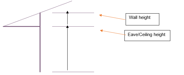
After you draw the wall lines, it is necessary to project them to their actual height. Walls may be projected up or down from the digitised wall lines. In order that the wall lines are compatible with the AppliCad roofing products, the wall lines you draw to create the perimeter for the roof geometry are at the top of the wall, if you have a roof in your model. If you do not have a roof in your model then the wall lines would typically be on the floor level (the CPL).
Select [Project Walls], a dialog box is displayed.

[Project Wall Lines] has multiple options that relate to whether the walls project up to the roof plane(s) and/or down to floor or ground level.
The [Project wall Up to Roof] simply takes all walls up to the under side of the roof planes. If a wall line extends beyond the perimeter of the roof for any reason, you can set the wall height to extend to. You might use the Measure function [m] to establish the height of the eave line to set the correct height.
If the walls are to be projected to the whole roof, then select the [All] button. On occasion, it may be necessary to select the walls and roof planes separately then use the [Locate] button. The walls will stretch up to the slope of the underside of the roof plane. The second options relate to projecting down (if required). [Project Walls Down by Amount] allows you to set the exact amount down or [Project Walls Down to RL (Z Hgt)] projects down to the CPL.
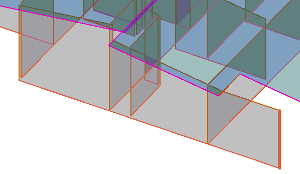
A wall line that extends beyond the roof with the height defined to the height of the eave line.
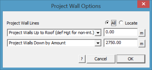
With a pitched roof, the distance from the ceiling height to the underside of the rafter is automatically calculated and the wall top is projected to the roof. You may choose to adjust this if required.
You would typically use the height calculated. In the box displayed above, this is the actual wall height for an eave height of 3000 and a roof pitch of 30°. After you enter the height of the walls, the wall lines are projected down to construct the walls. Each wall comprises the boundary lines and a plane entity.
![]()
Hint : It is a good idea to change your view to isometric at this stage so you can more easily see the 3D walls and select them to perform operations on later – use the function View > Isometric.
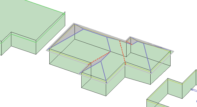
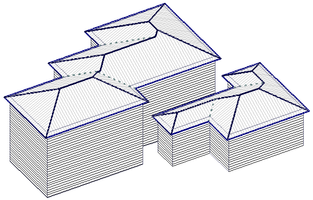
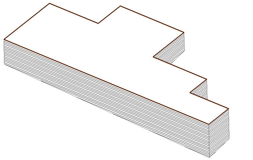
The wall lines are automatically tagged as Wall-Top, Wall-Base and Wall-Corner. These identifiers then define the type of flashing imposed on each line type. The following shows walls projected without the roof.
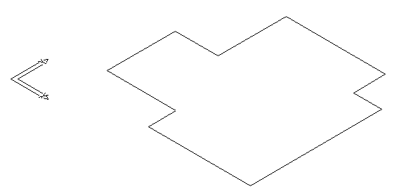
Walls before Project
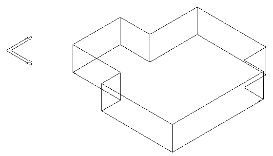
Walls after Projecting down to the specified height
Comments are closed.