Home
Welcome to AppliCad Help
Here you will find detailed descriptions plus tips and tricks to using AppliCad’s Roof Wizard software.
Select the menu option above and the complete function list for that option will be displayed.
The Process
The foundation of the Roof Wizard software process is based upon the creation of accurate roof geometry – that is, the roof geometry must first be correctly modelled in 3D space. It is from this model of the roof that the roof areas and quantities are extracted, plus a simulation of the laying of the roof material is done so that accurate material quantities are also extracted. Clearly, if the roof modelling is not correct, the estimate is not correct.
Note that it is possible to create a client proposal without the 3D model, but you lose the inbuilt checks that help you ensure the most accurate output result you can get. The 3D model gives you confidence in your result because it can be checked.
We have devised a simple five step process to ensure an easy, accurate outcome-
1. Define the roof geometry,
2. Check the roof geometry,
3. Select the roof covering material,
4. Quantify and cost the roof, and
5. Print client proposal, supplier orders etc.
It is a simple matter then of printing the necessary reports using the templates that you have defined. Standard report templates are provided so that you can make a start immediately. These may be edited at any time by you, to suit the needs of your business. To assist the operator in the roof modelling process, we have included some very sophisticated but simple, single mouse ‘click’ operations that allow a roof to be constructed from basic principles. The usual starting point for a roof using this system is a basic hip and valley roof where the pitch is the same with an eave height the same all the way around. From this just about any roof may be created by adding all the architectural features including dormers, atriums, gables, verandahs etc. (Specialised roof shapes such as a barrel vaulted roof, or simple flat or Single Slope roof are usually handled separately). If it can be built, you can model it.
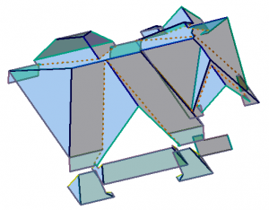
The AppliCad Roof Wizard software does not attempt to create a fully detailed three dimensional model of the structure. Instead it uses what might be best described as 3D CAD ‘roof shorthand’ to replicate the features of the building at full size, so that accurate and detailed material lists and labour summaries may be produced quickly and efficiently.
For example, instead of drawing the exact detail of a roof edge or eave with fascia, gutter and all the accessories to install it with all the CAD detail, we draw a single line that represents the roof edge and include ‘tags’ or non-graphical attributes that sets the rules for that line. These rules define what components comprise the roof perimeter edge – fascia, gutters, clips, screws etc and indeed all items that are required to correctly construct the fascia and gutter on the roof and they are associated with a single line that defines the roof edge or eave.
Essentially there are linear items and area items. All linear items are quantified per linear metre (or per foot) based on how they are supplied and accessories are associated based on their use with that linear item; that is, per metre (or per foot), per length, per piece or per end etc. It is essential that all building components are correctly defined at setup stage taking account of how they are fabricated and installed and the costs to do so. Once defined they are then used over and over.
After the roof geometry has been created, the roof cover material must be selected from a list of materials previously defined. Other fixtures and fittings that are required are automatically accounted for by the program. You may also select the type of flashings you want to use. The method of estimating the materials will depend upon the material type. In any case the process produces a complete material list for the roof including all fasteners, accessories, underlayment etc.
After creating the material list, complete reporting of the job is automatic, providing you with the ability to modify the quotation or client proposal prior to printing the necessary reports.
The functional descriptions are in the order as found on the Pulldown Menu as this is where most operators start when using the software. The Pulldown Menucontains all the software commands needed. The Icon Menu contains the most used functions and is a shortcut to the corresponding Pulldown Menu Functions.
Note: To find out what function is actually used for a particular Icon, turn on the Instructor – (Help > Instructor) and you will be able to access all the help you need.
Working With The Software
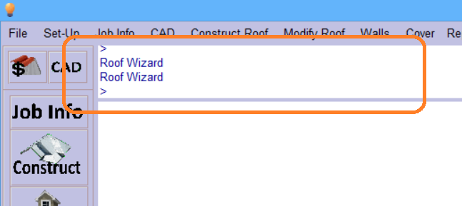
At the top of the screen, below the pulldown menus, there is the prompt area. All instructions and responses to commands are displayed here. If you are not sure what to do, look here first, it tells you what to do! It reads from the bottom up.
Context Sensitive Help
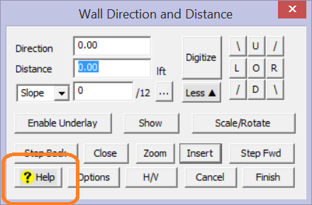
All the dialog prompts have a [? Help] button in the lower right hand corner. This is the help button for the command you are currently using. Select this and you will be taken directly to the page on the online Help (this site) where all the information you need about the current process is described.
If you have the AppliCad Instructor enabled (Help > Instructor from the Pulldown menu), the floating dialog box for the AppliCad Instructor is permanently displayed and chages to the brief over view of the currently selected command or function – similar to below:
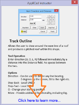
The Instructor dialog box may be moved around the screen to get it out of the way, or even moved to your second creen to be ready to help you, but completely out of your way.
If you need more details, select the “Click here…” option and you will be taken to the online help page (this site) for the current function.
The Menus
 The user interface comprises the Pulldown Menu, the Icon Menu and the side Text Menu (if it is turned on). Since any and all the menus may be accessed at any time the most efficient path to a command is usually just a single mouse click away. This section describes the commands on all the menus and indicates whether the command is an Icon Menu option or a Pulldown Menu option. Adjacent to the command description in these help files is the Icon from the Icon menu for that command where appropriate.
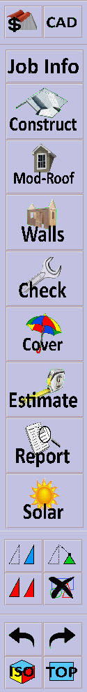
The top of the main menu has the buttons for Set-Up and CAD and below that, the buttons that take you to the Job Info dialog and the Customer dialog.
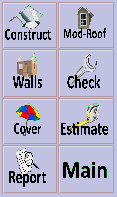
The intended menu options for the most efficient operation of the software are the Icon menus and these contain the primary menu functions in the order that a normal job is tackled – the five steps typically used are a single click away. Each subsequent menu is comprised of three common menu options.
Icon Main Menus
This menu is common to all Icon menu functions. These menus are described in detail below. Note that there is a Full Version (shown here) and a simple version with seldom used icons left off. To turn them on and off go to File > Layout > Full or File > Layout > Simple.
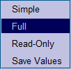
The Read-Only menus are displayed automatically if Roof Wizard is installed and not licensed. This allows you to install Roof Wizard on any computer on your network and the operator can view, check and print client proposals. They cannot create jobs, change or save jobs in ReadOnly mode.
Group Menu

This menu is common to all Icon menu functions and provides for Move, Stretch, Copy and Delete operations. Move a line or point; Stretch a line or point (taking attached entities with it); Copy existing lines, points or planes or Delete any entities, one at a time or as a group.
Utility Menu
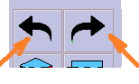 This menu is common to all Icon menu functions. It provides for Undo of the last few commands (back to the start of the session), or Redo if you Undo too far.
It also has the View > Select > Iso and View > Select > Plan View options. Moving around the model space is almost exclusively done using the mouse – see below.
The Roofing Menu
The Roofing menu provides all the functions for creating roof geometry, checking the roof geometry, defining and selecting materials to cover the roof and reporting the roof. Each option is explained in more detail under the appropriate menu heading. The Main button takes you back to the starting or top level icon menu.
3D CAD Functions
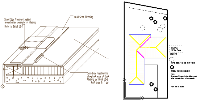
The icon menu also contains the button that provides access to the fully integrated 3D CAD menu functions. The CAD menu provides all the functions for creating any 3D modelling of anything – Inserting Lines, Circles, Curves, Text, Figures, Surfaces and Dimensions. You can draw a space shuttle using these functions if that is what you wish to do.
Selecting the CAD icon takes you to the CAD icon menus. You might use the CAD commands to create a workshop detail or to annotate a roof plan for submittal. All your advanced 2D CAD drafting and 3D CAD modelling needs are met in your roof estimating package with the included CAD tools. The 3D CAD modelling functions will be used for general drafting of roof details (left) or site plans (right) and are very useful skills to learn.
Mouse Controls
For most effective use of our software a three button mouse is recommended, or at least a two button and scroll wheel mouse.
The left mous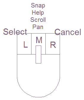 e button is used to select a command or digitise a point on the screen. The right mouse button is used to cancel, finish or abort a command. The middle button is used to snap to an existing point or line end point. It may also be used to bring up the “inline” commands and online help.
If your mouse is fitted with a scroll wheel, this would be used as a ‘middle’ mouse button in the normal way.
The middle mouse button can also be used to zoom scroll in and out and around your model. The middle mouse button may also be used to perform a Zoom > Fit-Screen by double clicking the middle mouse button any where in the screen work area. Hold down the middle mouse button anywhere in the work area and ‘pan’ the job.
If you hold down the Ctrl key and move the middle mouse button, the view will spin around the selected screen point.
Note: If you do not have a middle mouse button, hold down the shift key and use the left mouse button for the functions of the middle button.
Enhanced Mouse Controls
Using various combinations of the Shift, Ctrl and Alt keys in conjunction with a double click of the left mouse selection has a range of additional context specific functions, especially useful when modifying the model and checking the model.
On selection, the various options are displayed in the prompt area of the screen as shown here, followed by the appropriate functional dialog box as summarised below. A ‘tool-tip’ is displayed as a reminder.
| Summary of Enhanced Mouse Control Functions | ||
| Hold the key(s) and double-click [DC] left mouse button on a line or plane entity | ||
| Lines and Planes | ||
| On any line | DBL Click (DC) | Change Line Type |
| On any plane | DBL Click (DC) | Change Plane Material |
| Modify Roof | ||
| On an Eave Line | Alt+DC | Dormer |
| Ctrl+DC | Drop Eave | |
| Shift+DC | Slice Hip | |
| Shift+Ctrl+DC | Atrium | |
| On a Ridge line | Alt+DC | Dutch Gable |
| Ctrl+DC | Hip To Gable | |
| Shift+DC | Split Gable | |
| Shift+Ctrl+DC | Gable to Hip | |
| On a Gable/ Step line | Ctrl+DC | Extend Barge |
| On a Box Gutter/Apron line | Ctrl+DC | Cricket |
| On a Hip or Valley line | Alt+DC | Hip-Valley Gable |
| Ctrl+DC | Hip-Valley Dormer | |
| On a Plane entity | Alt+DC | Change Pitch |
| Ctrl+DC | Link Planes | |
| Shift+DC | Change Plane Storey (also changes
the storey of lines attached to it) |
|
| Shift+Ctrl+DC | Merge Planes | |
Comments are closed.