Track-Walls
 Track Wall Perimeter
This is the basic command for drawing wall perimeter lines. To create walls, you must project them after you draw the wall lines. You would use this command to draw the wall lines given the direction and length of each wall.
When you select Track-Walls, you first select a starting point, then the Track Lines dialog box is displayed.
This dialog box lets you enter directions by clicking one of the accelerator buttons (up, down, left, right), or one of the half angle directions (\ or /), or by entering the direction directly into the direction field. The direction is defined as 0 up the screen then positive clockwise. This is much like a compass bearing approach. The distance you simply enter directly into the distance field.
When you want to insert a new wall line, click Insert or hit the enter key. Then you will see dotted wall lines drawn on the screen, annotated with a wall number and the length of the wall. You will also notice that the shape is automatically zoomed to fit the screen.
When you want to automatically close the shape, click Close.
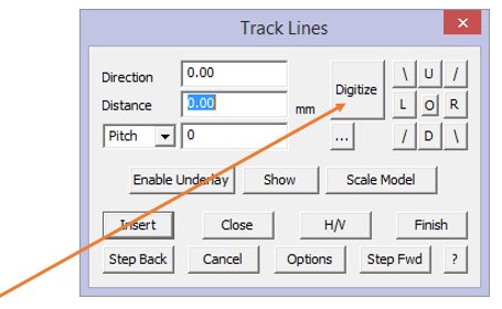
If you have horizontal and vertical distances defining the wall (rather than direction and distance) then click Hor-Vert. If you make a mistake with an input, click Stepback. If you want to re-enter values you stepped back over, then click Stepforward.
When you have finished entering walls, click Finish. When you click Finish, the wall lines are drawn.
You can enter the direction more quickly by using coded input. That is, if you type u50 in the distance field, then click enter, this input is read as Up 50. You can also use the characters of d, l and r for up, down, left and right.
 Digitise Wall Perimeter
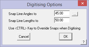
You would use the digitise option command to digitise wall perimeters from an underlay image, or if you know the coordinates of the wall corners. When you select Digitise, you enter the constrain angle and the constrain length. These values are used to round your input to some “nice” values. If accuracy is important, then set both of these to zero (0) so that no rounding will occur as you select points on screen.
By clicking [OK] you will then be prompted to enter the required storey. Simply enter the storey and click [OK] to continue. When you digitise each corner, you will see a dotted wall line drawn as well as the length of the line.
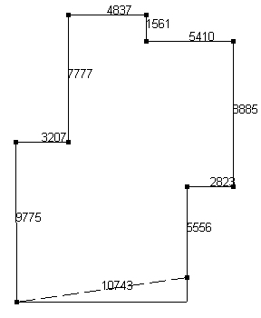
After digitising a wall outline
You will notice that when you close the outline by snapping to the last point, the last leg is adjusted so as to maintain the constrain angle you set earlier. If you do not snap to the first point to close the outline but click the right mouse button, the Close dialog is displayed.
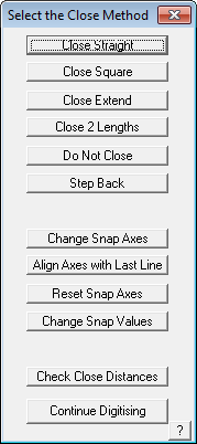
Close Straight This simply joins the last point to the first point
Close Square This creates another corner
Close Extend This extends the last direction to intersect the first wall.
Close 2 Lengths Prompts the user to close to a pre-defined line length
Don’t Close If there is a gap between the last and first points, then it does the same as the Close Straight method
Step Back Allows the operator to back track in the event that the line digitised is incorrect.
Change Snap Axes Allows the operator to change the direction of the Construction Plane (CPL) so as to continue digitising at a different orientation angle to the previously digitised lines. To access, when you need to change the CPL direction, right click the mouse and then select the option. The operator is prompted to select the origin of the new CPL, then the X axis of the CPL and then the Y axis of the CPL. Then select [Continue] Digitising. This may be repeated as many times as required until the job is completed. To finish, right click and select Close Straight or Close Square as required. The CPL may be reset to normal model origin by selecting
Reset Constraint Axes. It is also useful to have the constrain angles set, typically to 45° so as to ensure that your outline is square at all corners.
Align Axes with Last Line Rotates construction plane axes with last digitised line.
Reset Snap Axes Resets the snap axes to original settings.
Check Close Distances This command allows you to check the final two distances before you close the outline.
[Continue] Digitising Lets the operator back into the digitise process.
To enter coordinates you would first know what the wall lengths are. At the relevant prompt in the prompt area of the screen (typically at the bottom of the screen) you would enter (x,y) coordinates in one of the following ways:
Locate next point LOC> 10, 0 {10 units in the x and zero in the y}
Locate next point LOC> -10, 0 {-10 units in the x and zero in the y}
Locate next point LOC> 10’6”, 0 {10 foot 6 inches in the x and zero in the y}
Locate next point LOC> 10.5, 0 {10.5 feet in the x and zero in the y}
The above coordinates represent absolute coordinates whereas you could use incremental coordinates. Incremental coordinates are with respect to the previous point you enter.
For example, to draw a building 20 foot long and 50 foot wide, you could enter the size as:
Locate first point LOC> 0, 0 {Make 0,0 the starting point}
Locate next point LOC> i 50, 0 {Move 50 feet in the x}
Locate next point LOC> i 0, 20 {Move 20 feet in the y}
Locate next point LOC> i -50, 0 {Move -50 feet in the x}
Locate next point LOC> i 0, -20 {Move -20 feet in the y returning to 0,0}
Remember that this command simply draws wall perimeter lines or outlines and that you must project the wall lines to form walls.
 Track-Single-Wall
This command allows you to track around the outline of a single wall elevation. As with Draw-Single-Wall you can insert multiple wall elevations on the one job. The basics of this command also work the same as Track-Walls.
Comments are closed.