Tapered (Metal) Panels
Tapered (Metal) Panels
(Pulldown Menu Only)
This function is only available from the Pulldown menu. It is used to create a cutting list for tapered standing seam panels automatically. The panels will be bound by an outline comprising at least one arc and may be pitched up or down.
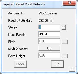
Selecting the option Estimate > Tapered panels > Generate presents the following dialog box.

Arc Length Displays the actual length of the defining arc. The arc may be the high point or the low point of the geometry, but is usually the edge that defines the widest edge of each panel.
Panel Width Max. The width of the widest part of the panel.
Storey This sets the pay scale to use for the installation.
Num. Panels Displays the number of panels that will fit along that arc. This would typically be modified to a whole number of panels.
Pitch The pitch or slope up or down from the defining arc.
Pitch Direction Either up or down from the defining arc.
Eave height The eave or gutter height of the defining arc.
Defining the Geometry
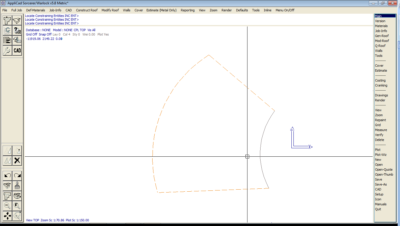
Prior to generating any Tapered Panel roofing panels, you need to define the geometry that is used to place the panels upon. The geometry can be created as a 2D outline or profile, while the panels will be drawn accurately in 3D up the slope as defined by the pitch. The reasoning for this is that the geometry is generally provided from an architectural CAD model and is more often than not provided in 2D and may be imported directly into the workspace.
You may also draw the outline by using the tools provided in AppliCad. Typically use the CAD > Arc > Insert and CAD > Line > Insert functions.
Creating the Panels
Once the geometry has been created, define the Tapered Panels using the Estimate -> Tapered-Panels -> Generate command. Select the Roof Material to use. Typically this will be a standing seam profile previously defined under Set-Up > Metal Panels.
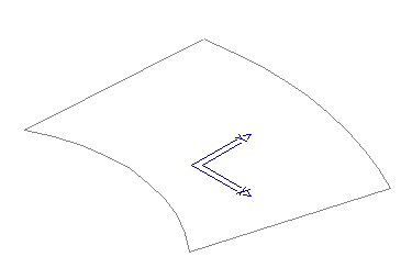
Locate the arc defining the tapered panel layout, near the lay start end. The panels are generated from that end. The dialog box for the roof parameters is displayed.
Once modified, the operator is then asked to identify the entities that constrain the panels. These are essentially the remaining entities in defining the panel extents and should be located in order:
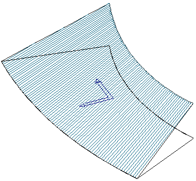
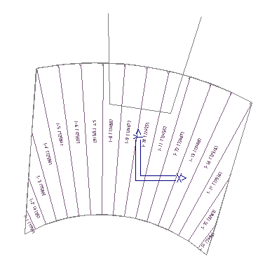
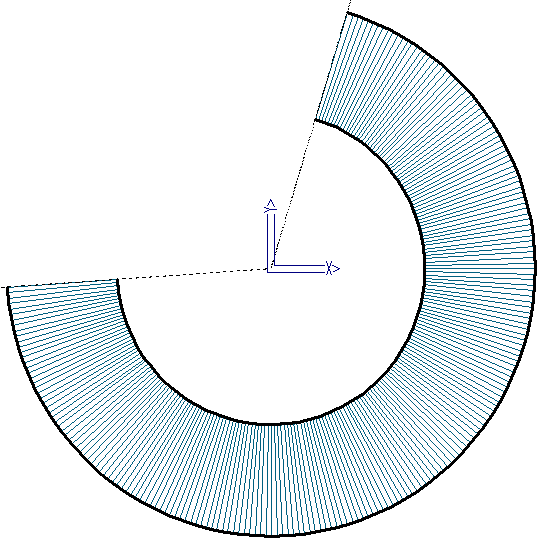
Once the constraining entities have been defined, the panels are drawn according to the constraining shape and the information specified in the previous dialog. An example of panels being drawn on our constructed geometry is provided below:
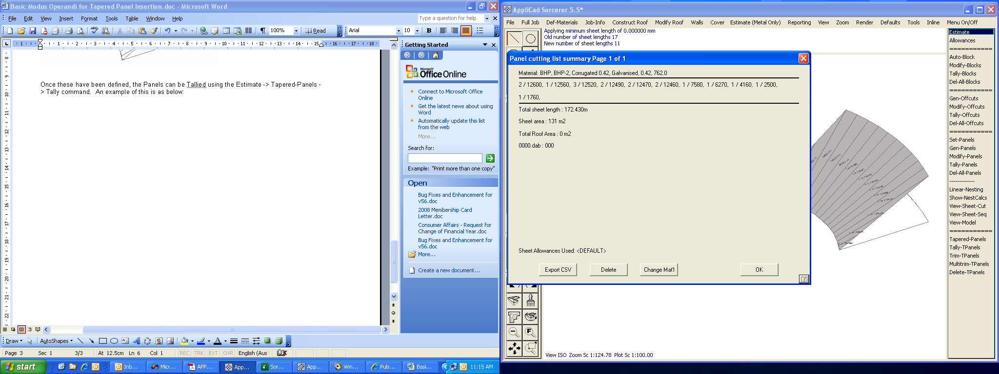
Once these have been defined, the Panels can be quantified using the Estimate > Tapered-Panels > Tally command. An example of this is as below:
Trimming of Panels
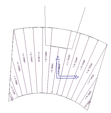
If a Tapered Panel needs to be trimmed around a roof feature, the Estimate > Tapered-Panels > Trim command can be utilised. As an example, we have provided some graphics that may be required to have the panels trimmed to.
In this example, we would normally trim the 2 centre panels, thus leaving the 2 outside panels at their maximum lengths for trimming in the field. Part of the panels actually extends to these lengths:
When selecting the command, we simply select the panel to trim and then select the location to trim the panel to. In this instance, we can simply snap using the centre mouse button or just use the left mouse button. Re-Tallying provides the new cut lengths prior to Reporting the job.
Place Dimensions
The Place-TP-Dimensions feature allows the user to place documentation on the roof drawing about each panel, so that construction information can be included along with the roof plan/drawing. This is useful when panels are being constructed on-site.
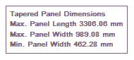
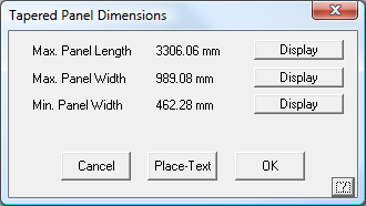
The user must first select the defining circle/arc that determines the Tapered Panel path. When defining Tapered Panels, this is the first circle/arc selected. Once selected, a dialog box will appear highlighting the 3 major items that can be displayed, such as the Maximum Panel Length, and the Panel Maximum and Minimum Widths. Selecting the Display button allows the user to define what to display and then selection of the Place-Text button allows the text to be placed onto the Drawing in an appropriate location.
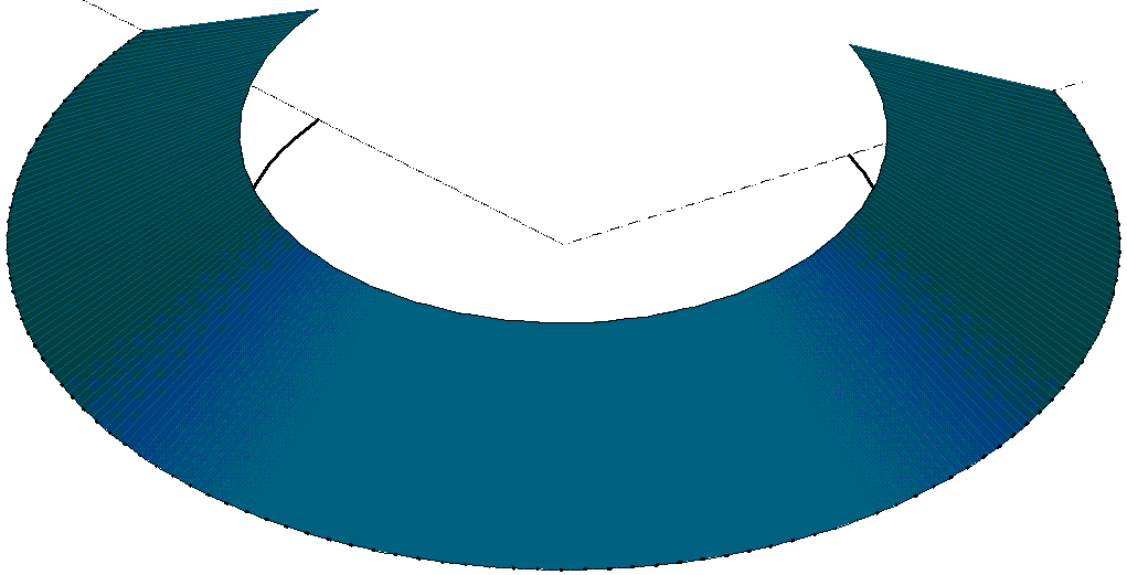
Some very elaborate shapes may be created and panels calculated for. The example below is just one more situation. Almost any combination of shapes where the defining edge is an arc.
Delete Tapered Panels
This function deletes a set of Tapered Panels by selecting the defining arc/circle.
Comments are closed.