Solar – Shadows
 Shadows
This function allows the operator to create shadows for a range of days and/or times (or just one day and time) and save the results to different layers for later use. An animation of the series of shadows may be produced and saved as an AVI file in whatever format is available on your PC.
Validation of AppliCad’s Shadow Calculation Tool
The AppliCad Shadow and Aggregate-Shadow Tools use complex mathematics to determine the position of the sun and assumes rays from the sun are parallel for the purposes of determining shadow positions. Such assumptions are sufficient for the majority of cases and given all AppliCad functions utilise double-precision (8 byte) floating point accuracy within a millimetre-based modelling system, this accuracy is maintained across all of AppliCad’s tools.
Sun Positioning
The position of the sun is perhaps the single most important factor in determining the accuracy of shadow diagrams. AppliCad software uses a simple four-step process in calculating the sun position. These steps are:
- Specification of year, month, day, hour and minute, along with a time offset from UTC (Universal Time Coordinate Origin) to determine a Julian Date. Julian dates are used for scientific purposes by the astrological community to present time in days and fractions of a day since January 1, 4713BC, Greenwich Noon.
- Calculation of approximate angular solar coordinates using a simple mathematical algorithm based on the Julian Date. These coordinates are approximated to an accuracy of 1 arcminute within two centuries of 2000. Thus, this accuracy is sufficient for the year period 1800 – 2200.
- Calculation of a sidereal day from the Julian Date. This is used for the next step in the process and simply calculates the sidereal time, which is a method of timekeeping relative to the fixed stars as opposed to our local sun. Our calculation in this instance is accurate to 0.1 seconds, or approximately 1.5 arc seconds of the sky.
- The final part of our calculation utilises the approximate angular solar coordinates provided from step two, along with the sidereal day calculations from step three to determine the azimuth and altitude of the sun relative to a position on Earth. The position on Earth is provided in terms of latitude and longitude, passed in as double-precision floating point values and is returned as the same precision variables from the function.
Single Shadow Calculation
AppliCad’s single shadow method positions the sun in the sky at a height of 5 kilometres and then requests the user to locate the planes onto which to cast shadows. All shadow casting elements (planes, ruled surfaces, surfaces of revolution and sub-figures containing these elements) are then selected for processing. Each shadow-producing element is triangulated (based on circle and curve tolerance factors that can be set by the user within the software) using a Delaunay triangulation method.
Triangle shadows are calculated and clipped against the shadow planes selected with shadow triangles falling outside the shadow planes being disregarded. Triangles falling on an edge are clipped and merged with any other triangle planes already within the planar polygon.
The net result is a complex shadow polygon that is then tagged as a shadow polygon and placed onto a specific layer based on the time and date of the required shadow.
Aggregate Shadow Calculation
Shadows calculated across a range of times can be performed using the Gen-Insolation tool which provides a less accurate solution but generally much faster calculation times for very complex models. The Aggregate Shadow Calculation tool divides planes up into squares (or pixels) with the size being specified by the user. Again the sun position is calculated in the sky and placed at a height of 500 kilometres.
A line is drawn from the centroid of each pixel to the sun position and a simple calculation is determined to see if any planes cut this line and if they do, the pixel is considered to be in shadow and the whole pixel is greyed (in shadow) without any clipping being performed. If not, the pixel is left white and the calculation continues onto the next pixel.
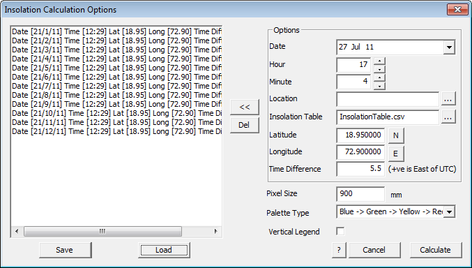
Insolation Calculation Options
Selecting the option brings up the Shadow dialog box:
The first thing to do is plan your shadow sequence – do you want same time on a series of days in a month or the same day each month or a series of hours in a day at say the winter and summer solstice (the shortest and longest days).
Once this is decided, then set your sequence up to give the required results. Typically, you select your date first.
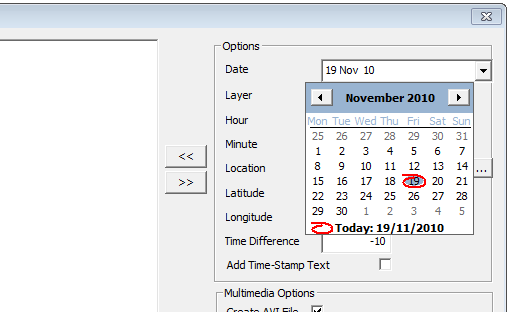
Selecting the date field drops down a calendar where you select the day you wish to prepare a shadow sequence for. The next step is to set the starting layer for the sequence of shadows. It is usual to have each sequence on a different layer so that each shadow sequence may be reviewed independent of other shadows.
If one is preparing a sequence for a particular day, say from sun rise to sunset during the shortest or longest day (June 21 and December 21 respectively), then the define the hourly increments against each layer starting at layer 100. As the hour is incremented, the layer is automatically incremented from 100. As each hour is defined, select the double left arrows [<<] button to add that time to the list of times that the shadows will be calculated for. If you wish to delete a time/layer group highlight that group and select the double right arrows button [>>].
If you believe that you will use this sequence on a regular basis, save the sequence for future use. This is particularly useful if your business is normally around a particular city or region.
The software needs your location. Select your location from the list (Latitude and Longitude and time difference are pre-defined) or define a new location. Define the latitude and longitude for that location and the difference from UTC – Coordinated Universal Time is closely related to Greenwich Mean Time (GMT). Note that daylight saving adjustments are not automatically made.
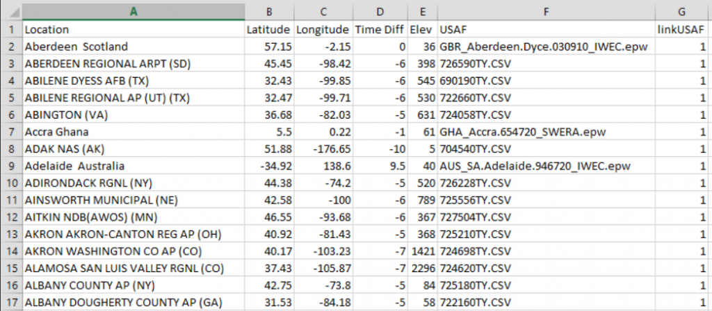
This information is stored in a text file located in the …\Roof Wizard\User folder called locations.csv and looks like this when opened in MS Excel…
If you wish to be prompted for the date and time text to be added to the sequence, indicate that by checking the ‘Time-Stamp’ box.
You may also select from a list of pre-defined cities. Select the […] button next to the Location field. You may add locations and edit details of locations. Note that longitude Eastings are positive values and Westings are negative values; latitude Northings are positive and Southings are negative.
Time east of Universal Time Coordinated (UTC) are positive and west of UTC are negative.
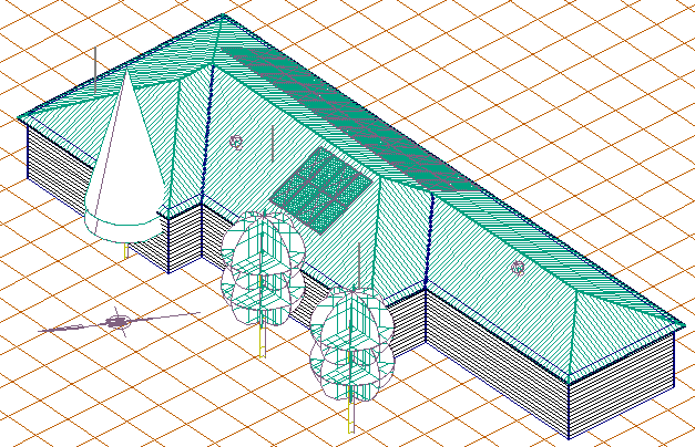
You can run the study to check the result on your model without creating an AVI file. Click the Run Study button and the software prompts you for the layers to cast shadows upon. Some preparation ahead of time, setting up the model is assumed at this point. It is assumed that you have added the roof fixtures (panels, AC Units, plumbing vents etc) and perhaps a site base and whatever trees and surrounding structures that are part of the study and that will impact on our study.
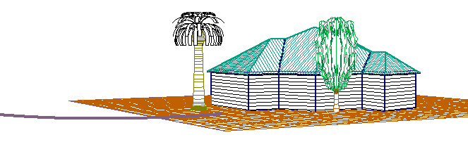
Also check that the whole model is oriented towards north. The top of the screen is considered to be north by the software, so you may have rotate the whole job to face north.
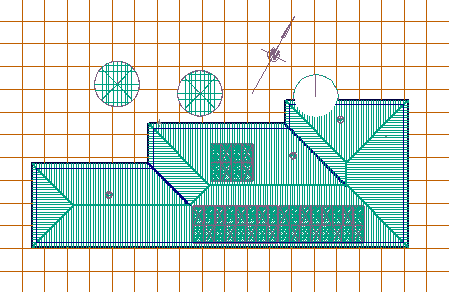
Before rotation to North.
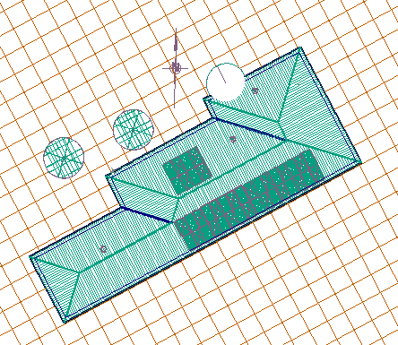
After rotation to North
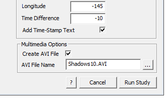
Now select [Run Study] and the software firstly creates the shadows on each defined layer in sequence and saves the information away, then it prompts for the Codec to use to write the AVI file and then writes an AVI file into the operator’s User folder.
The AVI file will vary in size substantially and this is determined by the complexity of the model, the number of sequences and the Codec used to create it.
![]() Note: the creation of the animated file uses Codec’s that are resident on your PC and not supplied by AppliCad. For a discussion about Codecs, the formats and how they work, refer to your PC manual or perhaps search Google for a detailed explanation. In short, a Codec is the embedded application that compresses the screen graphical data in a form that might be replayed in a media player such as Quicktime® or Windows Mediaplayer®. The size of the resultant AVI multimedia file is a function of the Codec used.
Note: the creation of the animated file uses Codec’s that are resident on your PC and not supplied by AppliCad. For a discussion about Codecs, the formats and how they work, refer to your PC manual or perhaps search Google for a detailed explanation. In short, a Codec is the embedded application that compresses the screen graphical data in a form that might be replayed in a media player such as Quicktime® or Windows Mediaplayer®. The size of the resultant AVI multimedia file is a function of the Codec used.
To review your animation, open up Windows Explorer, navigate to the User folder and find the file name that you specified. Windows will usually have made an association with different file type extensions and automatically select the correct program to open and play your animation.
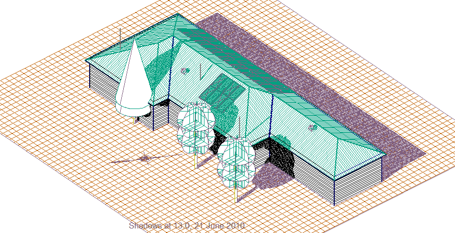
Date and time stamp
You may play this to your client or email it to them to review in their own time. Consider the size of the file before you automatically send it to your customer. He might not appreciate clogging up his email server with your huge animation files!
Create Animation
If you do not create an animation while running the Sun Study, you can create it later by selecting the option – Solar > Create Animation. With this option you may create the animation after the Sun Study has been run and you also have an option to create a ‘fly through’ animation or a ‘spin’ animation for your client.
![]() Note: the creation of the animated file uses Codec’s that are resident on your PC and not supplied by AppliCad. For a discussion about Codecs, the formats and how they work, refer to your PC manual or perhaps search Google for a detailed explanation. In short, a Codec is the embedded application that compresses the screen graphical data in a form that might be replayed in a media player such as Quicktime® or Windows Mediaplayer®. The size of the resultant AVI multimedia file is a function of the Codec used.
Note: the creation of the animated file uses Codec’s that are resident on your PC and not supplied by AppliCad. For a discussion about Codecs, the formats and how they work, refer to your PC manual or perhaps search Google for a detailed explanation. In short, a Codec is the embedded application that compresses the screen graphical data in a form that might be replayed in a media player such as Quicktime® or Windows Mediaplayer®. The size of the resultant AVI multimedia file is a function of the Codec used.
Layer On/Off Animation
When this option is selected the following dialog box is displayed and you will select the option Layer on/off Animation.
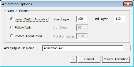
Set the start and finish layer you defined when creating the original shadow study (we have suggested that they start at layer 100 and through to how ever many layers you need for the sequence).
Next set the path and the file name for the animation file and click Create Animation. The screen will come to life making the file and the file saved.
The AVI file will vary in size substantially and this is determined by the complexity of the model, the number of sequences and the Codec used to create it.
 To review your animation, open up Windows Explorer, navigate to the User folder and find the file name that you specified. Windows will usually have made an association with different file type extensions and automatically select the correct program to open and play your animation.
Follow Path
This function is designed to provide a method of creating an animation that will show your client how their roof might look approaching it from the end of the street for example, along a ‘flight path’ that you define.
To use this option, first you must insert a curve in 3D space that defines the ‘flight path’ that transits your model, using the CAD > Curve Insert > Bezier function on the Icon menu. This is inserted onto the Construction Plane (CPL). Your model should now look similar to that below:
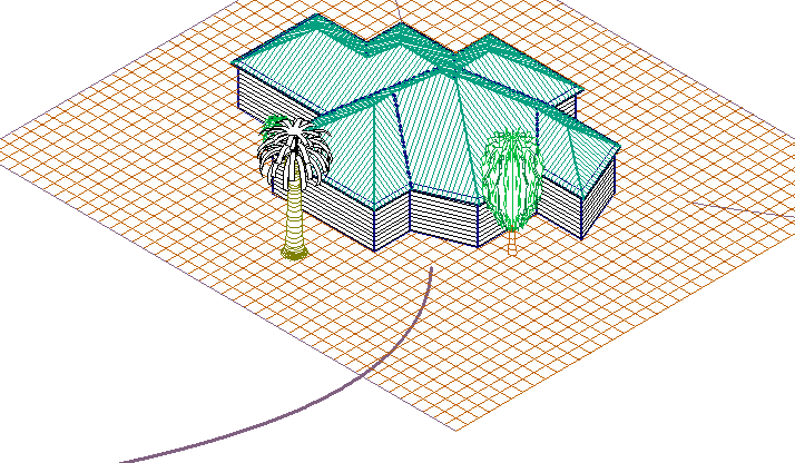
The inserted Bezier curve that is our ‘flight path’.
Now set you view to ISO View and select the Render > Create Animation > Follow Path option. Set the height of your eye and the file name to write the AVI file to and select Create.
You can add as much detail to your roof model as you like using all of the CAD functions. Just remember that the more you want to add, the more time you invest in your customer’s job.
Rotate About Point
This option allows you to create an AVI animation file by rotating about a point in the current view. It makes sense to do this in the ISO view, so change your view to ISO to begin with, then select the option Solar > Create Animation > Rotate About Point, define the AVI file name and the increments of degrees of rotation. Then select create and the AVI file is created.
You may play this to your client or email it to them to review in their own time. Consider the size of the file before you automatically send it to your customer. He might not appreciate clogging up his email server with your huge animation files!
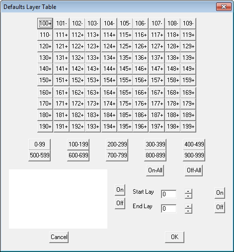
 Show/Hide Layers
The operator selects the start layer (select a layer beyond those layers used by the software – anything above layer 100 will work) and as the shadows are created, and each shadow calculation in a sequence of shadows is saved to that layer and incremented for each shadow calculation. If you start at layer 100 and do ten steps during a day, then the first shadow calculation goes on layer 100 and the next step goes on layer 101 and the next step to layer 102 etc.
The example below has layer 100 on and the other layers in the sequence are turned off.
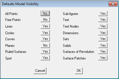
Show/Hide Entities
[Pulldown Menu only]
Allows the operator to select entities to be displayed along with the roof model and the shadows or insolation map.
Comments are closed.