Drawings
 Drawings
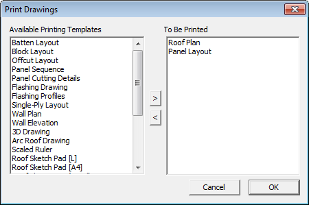
When you click Drawings, you can now print up to 8 different standard CAD drawings or any number of Drawings saved as Microsoft Word or Excel Templates. Refer to the process description for creating these at the end of this section of the manual.
The Select drawings to print dialog box is displayed from which you select the drawings you want.
| Drawing Name | Template Name | Intended Use |
| Roof drawing | Drawing-Roof | Shows the roof |
| Batten drawing | Drawing-Batten | Shows the battens on the roof |
| Block layout | Drawing-block | Shows the blocks on the roof as created by Auto-Block |
| Off-cut layout | Drawing-off-cut | Shows the cuts and off-cuts created by Gen-Off-cuts |
| Off-cut layout(Colour) | Drawing-Off-cut-Colour | Shows a colour coded printout of the Off-cut Layout |
| Panel layout | Drawing-sheet | Shows the sheets on the roof as created by Gen-Sheets |
| Panel sequence | Drawing-Sheet-Sequence | Shows the sequencing of panel cutting derived from Linear Nesting |
| Panel cutting details | Drawing-Sheet-Cutting | Shows the detailed dimensioned panels |
| Flashing drawing | Drawing-flashing | Shows the roof and dimensions for each roof line as detailed by Dimension-Roof Lengths |
| Flashing profiles | Drawing-Flashing-profiles | Details the workshop drawings for the fabrication of custom flashings |
| Single-Ply Layout | A4-Form | Shows the membrane layout generated by Cover > Select-Membrane > Layout-SinglePly |
| Wall Plan | Drawing-Wall-Plan | Shows a plan view of your wall outline |
| Wall Elevations | Drawing-Wall-Elevation | Shows you the elevations of each wall outline |
| Arc Roof Production Drgs | Found under Cranking.DAB | Details the workshop drawings for the fabrication of curved roofing |
| 3D Design Drawing | Drawing-3D | Shows the roof in a 3D view |
| Scaled Ruler | No template | Creates a scaled ruler with any odd-ball scale which allows random measurements to be taken from a copy of a plan. |
Once you click [OK], the particular drawings you want to print are first prepared for printing and then sent to your printer.
Section Reports in Commercial Mode
When commercial mode is enabled, several additional report options are available that allow for the ability to create individual metal cutting list reports per roof plane.
To prepare for a “Section Report” as we have named them, the user must define various areas of the roof as sections (typically “A”, “B” etc.) and then number individual roof planes within each section using the Set-Section function under Estimate > Set-Panels.
You use the Set-Sequence button to change the order of the plane areas to suit your method of working – typically from longest roof panels to shortest.
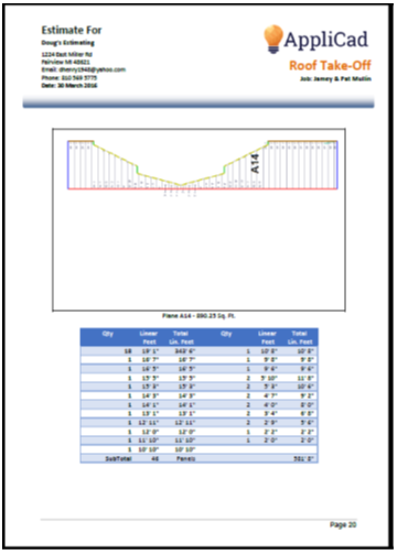
Once this is complete, a Section Report can be produced by simply utilising the ###SectionReport, ###SectionReport2 or ###SectionReport3 key text strings in your report template which will result in a report similar to that shown below with the plane area and the cutting list for that plane.
###SectionReport
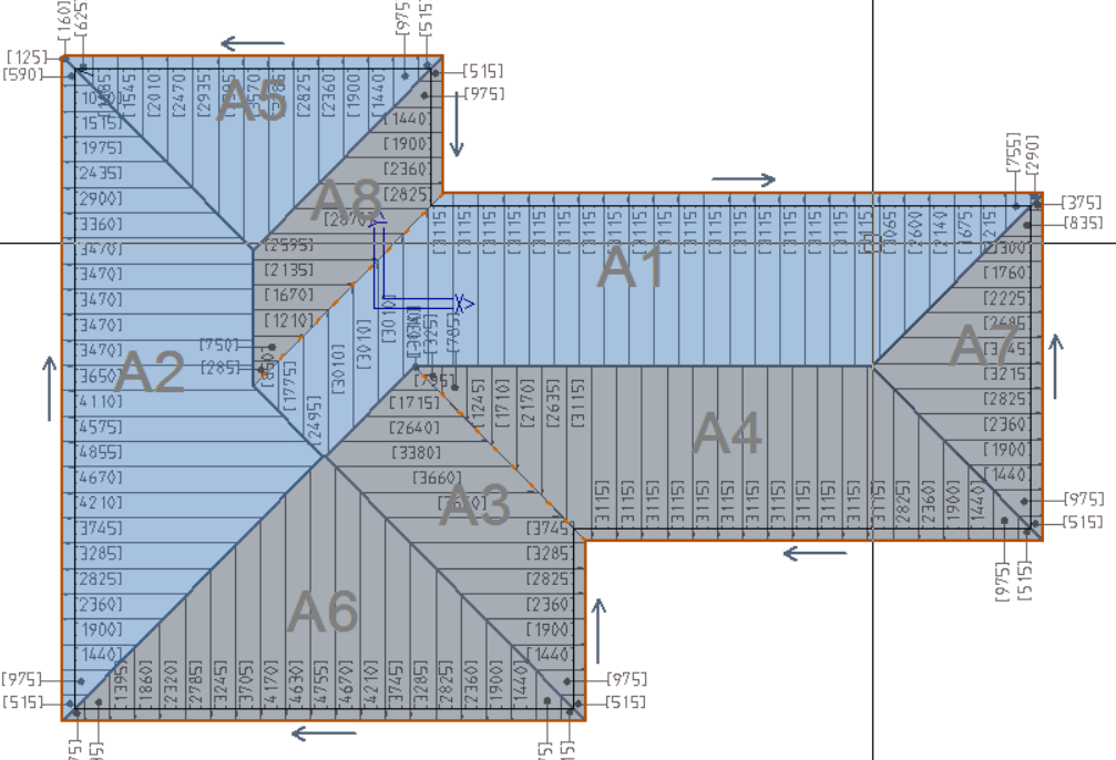
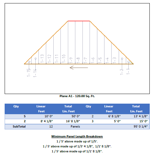
###SectionReport provides a layout of each roof plane in turn, and includes waste and plane area in the corresponding cutting list table for each plane area of the model.
###SectionReport2
###SectionReport2 provides a cutting list table for each plane area of the model and includes waste and plane area, without the graphical depiction of the roof plane area.
 ###SectionReport3
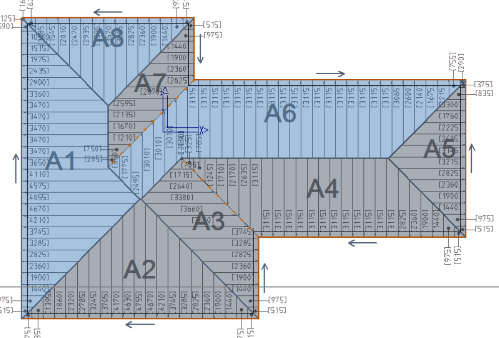
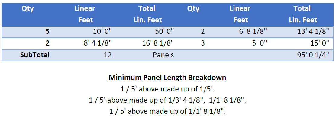
Removes the plane annotation numbers from plane imagery, as well as using double columns, losing Waste and Total Area per panel in the process over ###SectionReport.
Below is a closer look at the two column format of the SectionReport3.
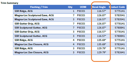
Typically associated with the full blown commercial mode reports are the Flashing Table which includes the angle of bend for each piece of trim. The angle of bend is calculated automatically by the software from the roof geometry. It uses the pitch of the roof and the angle made between adjacent roof planes.
###FlashingTable
Available for commercial roofing to display bend angle of flashing, the number of pieces of each length and the product code:
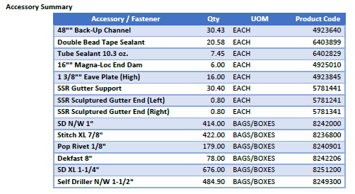
###FlashAccesstable
Available for commercial roofing to display accessories and fasteners associated with all the trim and panels in that job:
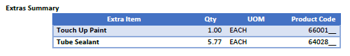
###ExtrasTable
Displays any Extra items selected for the current estimate.
Scaling the Roof Picture
Any report or drawing that incorporates a picture of the roof, draws the roof to best fit between the extents of the diagonal line input on the template on layer 999. Refer to the section of the manual dealing with defining templates. The roof picture is further constrained by a ‘proper’ scale factor so that the picture may be compared with other drawings of known scale. For example the best fit across the page might be 1:187. This cannot be compared to anything useful, so the software automatically adjusts this scale to 1:200.
You may also a diagonal line on layer 990 and then the software draws the flashing details onto the roof drawing report.
The range of scale options is defined in the software and these scales are 10; 20; 50;100; 125; 150; 175; and 200.
The operator may also define any other scale options. This is done by defining a series of scale values in a simple text file. The file must be called Scales.dat; it must be in the ..\User folder and be in the form of:
50
100
115
125
150
165
175
200
END
The word END at the bottom of the list is essential for this to work properly.
Comments are closed.