CAD Insert Arc
CAD > Insert > Arc
An arc is a model entity which is graphically defined by five associated points. These associated points define the origin of the arc, the start of its circumference, the end of its circumference and the length of its first and second axis respectively. The startpoint also defines the length of the first axis of the arc (i.e. the first axis point).
The second axis point is always located at right angles to the startpoint, with respect to the origin, in a direction dependent upon the method of insertion and the current CPL.
An arc can be inserted freely or relative to existing entities (e.g. as a fillet or as a scallop). The lengths of the first and second axes are equal for a circular arc. An elliptical arc can also be inserted by specifying different lengths for its axes. An arc can subsequently be trimmed and divided, and points can be generated around the circumference.
An arc is only graphically different from a circle because of the extra endpoint. It can be considered as a graphical portion of a complete circle or ellipse. A circle can be considered as an arc whose angle between its endpoints subtends 360 degrees.
Arcs are therefore included with circles in the listing of the List Count command and are listed as circles by the List Verify command. The visual display of arcs and circles can be suppressed by selecting the No option for the Circles modifier of the Defaults > Vis-Model command.
The five associated points of an arc can be selected with the snap/help button for exact co-ordinate location but they cannot be deleted without deleting the arc.
Arc Insert
The Arc Insert command enables the Arc Insert sub-menu which allows the insertion of arcs by defining point locations, radii or diameters. Elliptical arcs can also be inserted by defining point locations or axis lengths.
3-Points
Allows the insertion of an arc whose circumference passes through three selected point locations. The first point location selected is the start of the arc’s circumference. Together with this first point location, the next two point locations selected define the size and orientation of the arc. The third location selected is the end of the arc’s circumference.
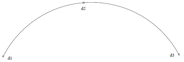
If the three point locations selected are collinear, an arc will not be inserted.
Radius
Allows the insertion of an arc whose radius is defined by selecting two point locations and whose subtending angle is defined by selecting a third point location.
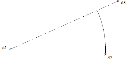
The first point location selected is the origin of the arc and the second point location selected is the start of the arc’s circumference. The radius and the orientation of the arc is thereby defined (i.e. distance and direction between the first and second selected point locations).
The third location selected defines the arc’s subtending angle relative to the second location selected. The arc subtends an angle anti-clockwise to the current view, about its origin, from the second to the third point location. The actual end of the arc’s circumference lies on a line that projects from the origin to the third point location and is at the defined radial distance from the origin.
Radius=
Allows the insertion of an arc, with a specified radius and an origin defined by selecting a point location whose subtending angle is defined by selecting another two point locations.
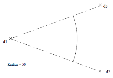
The radius is specified, followed by the selection of the origin of the arc and then the selection of another two point locations that define the arc’s subtending angle.
Diameter=
Allows the insertion of an arc, with a specified diameter and an origin defined by selecting a point location, whose subtending angle is defined by selecting another two point locations.
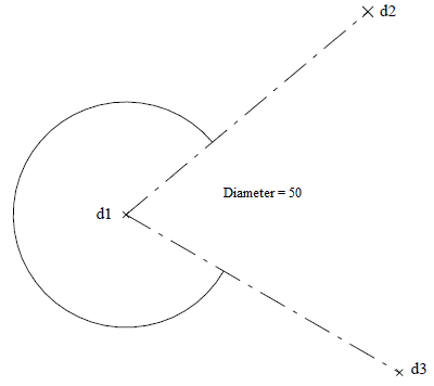
The diameter is specified, followed by the selection of the origin of the arc and then the selection of another two point locations that define the arc’s subtending angle. The arc subtends an angle, anti-clockwise to the current view about its origin, from the second to the third point location.
The actual endpoints of the arc (i.e. start and end of the arc’s circumference) lie on lines that project from the origin to the two respectively selected point locations and are at the specified
radial distance (i.e. half the specified diameter) from the origin.
Angle=
Allows the insertion of an arc with a specified radius and subtending angle.
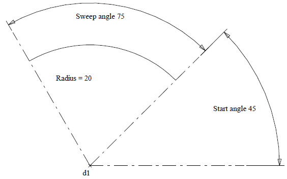
Radius Determines the radius of the arc.
Start Angle Determines the start angle, calculated anti-clockwise about the origin from the X-axis.
Sweep Angle Specifies the sweep angle, which is calculated about the origin, anti-clockwise to the current CPL from the start angle.
The arc is inserted about the origin, anti-clockwise to the current CPL from the start angle and therefore subtends an angle defined by the sweep angle, about its origin and anticlockwise to the current CPL, from the specified start angle. The endpoints of the arc (i.e. start and end circumference of arc) lie on lines that project from the origin at the specified angles and are at the specified radial distance from the origin.
Arc Fillet
The Arc Fillet command enables the Arc Fil sub-menu which allows the insertion of an arc as a fillet between:
• two point locations
• a point location and a line or circle
• two lines, circles or curves
• a line and a circle or curve.
The angle subtended by a fillet never exceeds 180 degrees.
Comments are closed.