Block Cutting
 Block-Cutting
A development of the long established ‘Blocking’ process is available where the estimator determines where roof sheets can go and more particularly, shows where the offcuts must go, as part of a block, to substantially reduce waste material – this is called ‘Block-Cutting’.
Developing a block-cut layout drawing is an interactive process that may result in multiple ‘correct’ results. In many respects this is what makes learning how to do this quite difficult – there is often more than one correct answer.
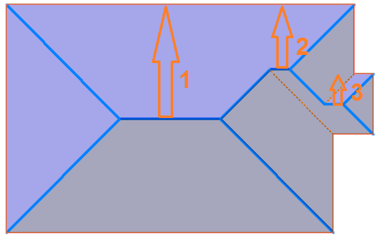
The first thing to look at is how many different ridge-to-eave lengths are there? In this example, there are three, so we are aiming for three sheet lengths in our sheet order cutting list or pack.
 It takes the blocks created and allows the operator to identify roof plane areas, block-pieces effectively sub-dividing the block to account for each roof plane, and to show on the block where each off-cut is expected to be extracted from and applied to the roof plane.
This Block-Cutting process is taking what roofing installers (at least those who reduce waste by flipping sheets around) actually do in the field and shows them exactly how to achieve the best fit, before they get to the job site. It is an interactive process that is ‘driven’ by the operator to get the required result.
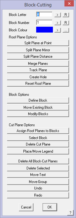
Block-Cutting Options
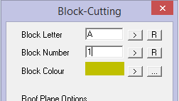
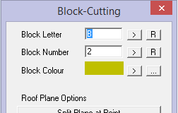
The block Letter, Number and Colour options set the designation that you will use to identify each block as they are associated with the respective roof planes.

They automatically increment, as each block-piece is applied to the block. The [>] button takes you to the next letter or number in the sequence; the [R] button resets to A or 0,
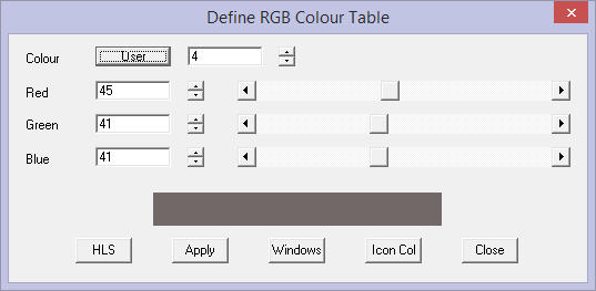
The block colour can be any of 256 colour numbers and any colour number can be any colour as defined under CAD > Defaults > Colour Table.
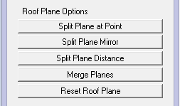
Block-Cutting > Roof Plane Options
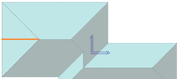
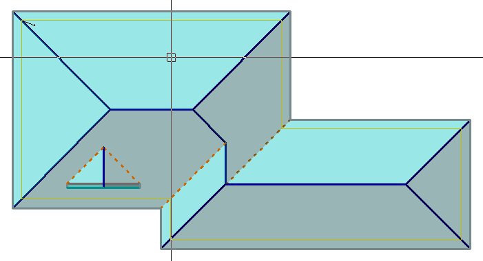
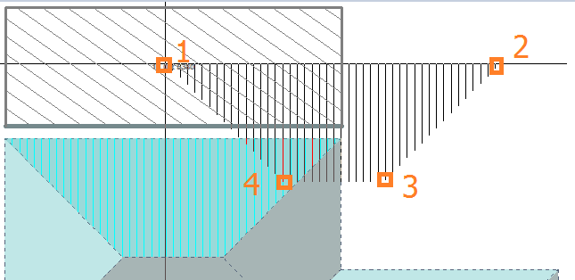
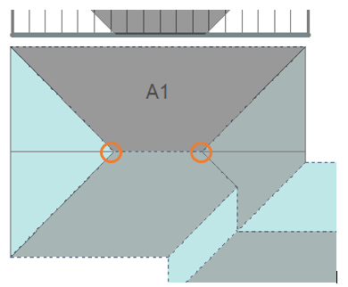
Split Plane at Point
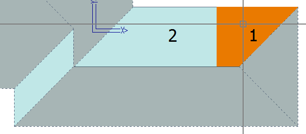
This function allows you to select a plane, in the example, the plane at the hip end (1), then middle button snap the apex of the ridge and hip for a point to split the plane through (2).
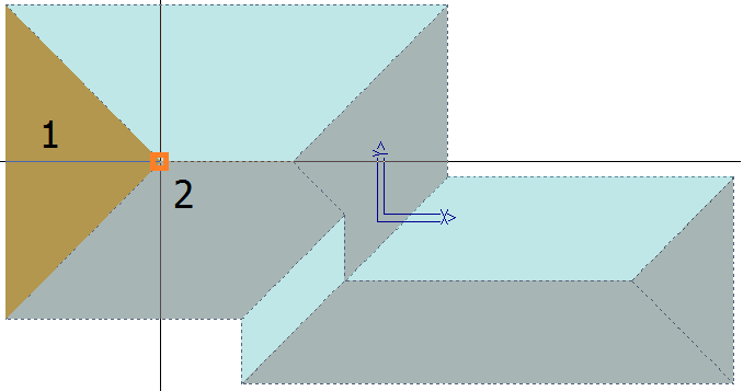
The hip end plane is split to form two block-piece planes that are available to use on the blocks as you create them.
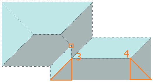
Split Plane Mirror
There are other situations where you need a bunch of extra block-pieces defined on the roof. The command Split Plane Mirror will give you a mirror image of a split point on the same plane.
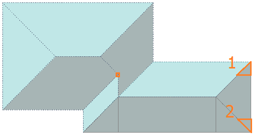
And the adjacent roof plane can be split in a similar manner to create block-pieces 3 and 4 using the same snap point.
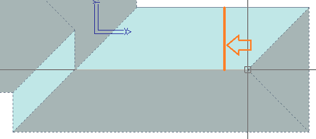
Split Plane Distance
This function allows you to split a plane to create a block-piece of a specific distance from a reference point. Follow the prompts carefully as you must define the reference point, the distance from and the distance to the location of your split line.
In this example, we needed a split line 1200mm (~4’) from the apex point to create a block piece that suited how we intended to utilise the block pieces.
Merge Planes
This option allows you to remerge planes that you might have mistakenly split. Planes 1 and 2 will become one again.
Reset Roof Plane
Removes the annotations that might have been placed incorrectly and allows you to do it again with new annotation.
Now you see it, then you don’t.
Block-Cutting > Block Options
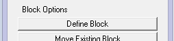
Define Block
This function automatically creates a block about the extents of the roof plane selected, then prompts to extend the block edge, if required. If the block is the correct size, then right click [Cancel] to place the block ready for placement of block-pieces.
Move Existing Block
Once a block is placed, you may decide to place it elsewhere to make room for new blocks around the roof model.
Modify Blocks
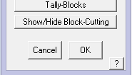 This brings up the Modify Blocks toolkit that allows all manner of modifications to the automatically created blocks. These functions are well described in the previous section on Blocking (as distinct from Block-Cut). The key function specifically relevant to the Block-Cutting process is the option Show/Hide Block-Cutting which turns the block-cut outlines on and off.
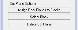
Block-Cutting > Cut Plane Options
Assign Planes to Blocks
Once you have created your blocks and split the roof planes into block-pieces, you then assign the block-pieces to the block.
You do this typically starting with the largest and most obvious block-piece and it will be annotated block-piece 1 – in this case block-piece A1. Then select the next block-piece to be placed and this will be annotated A2 etc.
As the block-pieces are selected, they may not be oriented to suit the placement onto the block, so use function keys F1 and F2 to rotate the block-piece. If the ‘snap-handle’ is not in the correct corner, use F3 and F4 to change the handle so you can middle mouse button ‘snap’ it to the block, repeating the process until all block-pieces are placed and that block is complete.
Select Block
If you have been moving around the model and changing blocks etc, you may need to re-select the block so that you can assign the block-pieces to the correct block.
Delete Cut Plane
This function deletes a cut plane that you might have created so that you can create a new one.
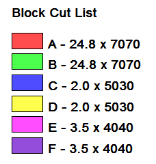
Place/Move legend
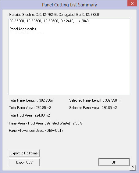
After all Blocks have been accounted for, you can use the function Place/Move Legend to annotate the Block-Cut drawing with the summary of the cutting list – for example:
Note that this example shows fractions of sheets. This can be adjusted to round up to whole numbers of sheets by changing the settings in Allowances.
Delete All Block-Cut Planes
Deletes all the cut planes so that you can start again. Sometimes you learn a more efficient way to do a job only after doing it a different way. Since this is so quick, don’t be afraid to try alternate ways to block and split planes.
Move Text
Moves the annotation text so it is easy to read.
Move Group
Allows you to move an entire block and all its block-pieces to a different part of the screen sothat the report is more easily read.
Undo
Undo the last operation.
Redo
Redo if you Undo too far or you decide that the Undo was actually correct.
The Block-Cut Process
The Block-Cutting process can be loosely broken into three steps – Define the Block; Place the Block and Assign Roof Plane block-pieces.
Select Estimate > Block-Cut to bring up the Block Cutting dialog.
Set the first Block Letter, colour and number. If a roof panel has not been selected, then you will be prompted to select one from your previously defined panels.
Step 1 Define Block
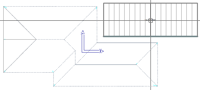
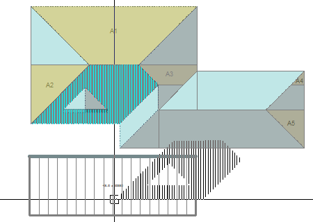
Select Define Block and select the first roof plane you wish to put a block on – Step 1.
Once you click on the plane the software asks you to locate any Block Edge Lines you want to Stretch. (This may be required if the automatically inserted block doesn’t extend into the area that you wish to apply the block to). This can be any of the lines you just need to stretch them one at a time.
 In this case this block is [OK] as it is, so right click [Cancel], and the Block will attach itself to your cursor and you can place it outside of the roof area ready for roof planes to be assigned to the block.
Step 2 – Place Block

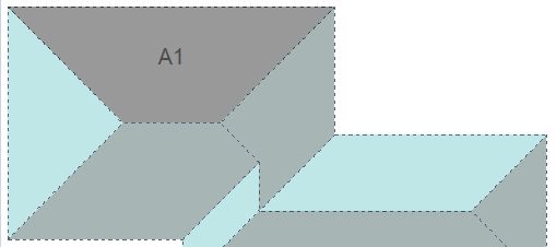
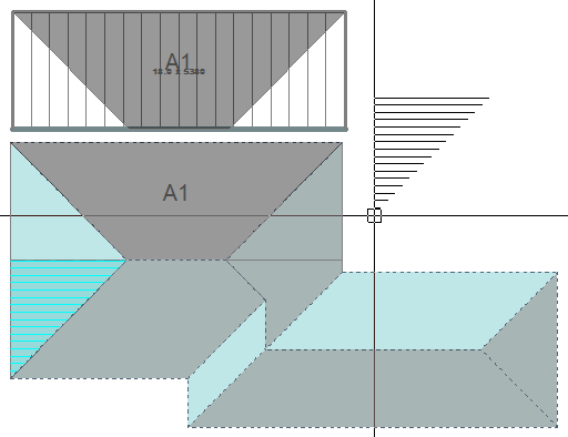
Next select Assign Roof Planes to Blocks and select the section of roof you want to be called A1.
 Rotate Plane/Change Snap Point
This will attach the roof plane to the cursor and you can use function keys F1 & F2 to rotate the plane and use F3 & F4 to select a point on the plane that makes it easy for you to attach it by ‘snapping’ to a point on the block outside the roof.
Alternate ‘snap points’ using F3 and F4 to conveniently snap to the corner of a block.
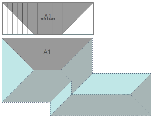
Step 3 – Assign Roof Planes to Block and Repeat until Complete
Middle mouse button, ‘Snap’ the roof plane to the corner of the block. Once attached to the block it will display as A1.
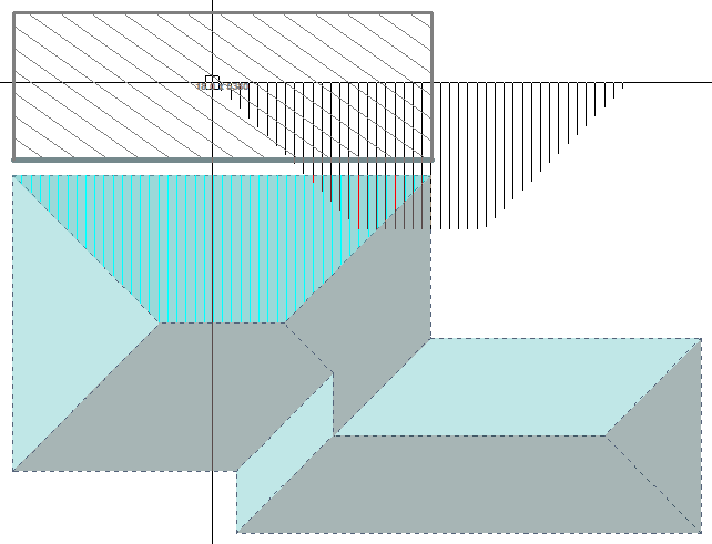
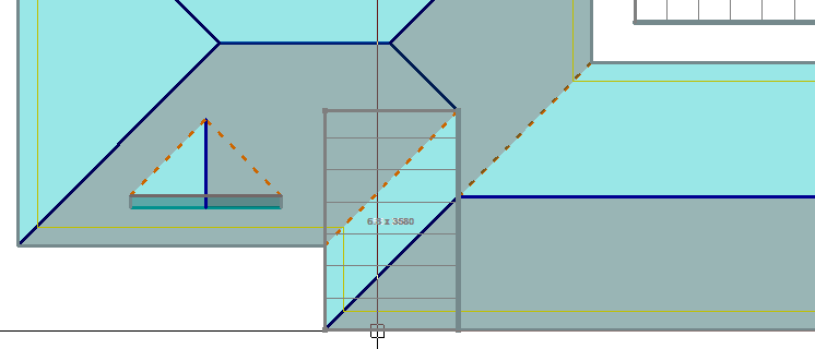
 To get the off cuts into the correct place right click to cancel from the Assign function, and select the Split Plane at Point command.
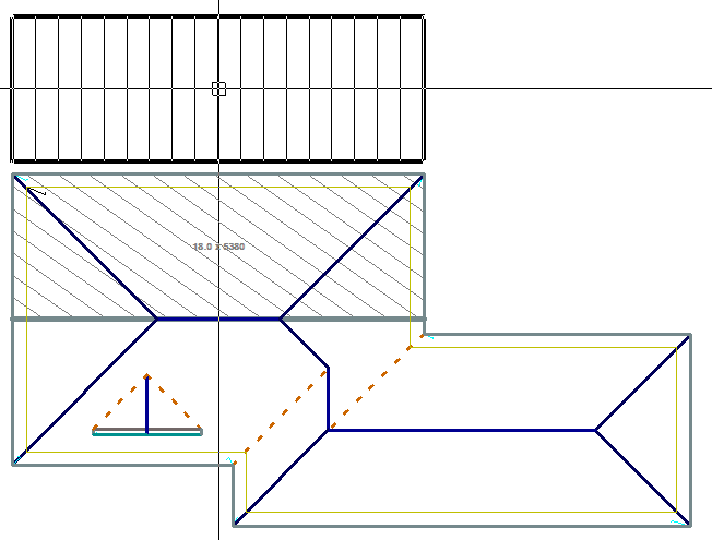
Using the far left plane as a starting example, select the roof plane to divide and then snap to the point at which you want to split the plane – in this instance it’s the apex of the two hip lines, you should now see a line that separates the 2 halves of the hip end triangle.
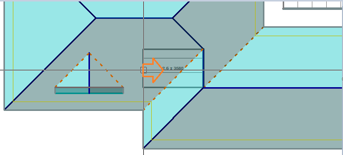
Select the opposite hip apex by snapping, and divide that roof plane as well.
Now go back to Assign Roof Planes to Blocks and by selecting one side of the split line and using F1 or F2 to rotate the block-piece until it fits in place on our block taking note of the pane lay direction indicated by the hatch lines.
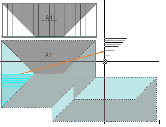
F1 or F2 to rotate into the correct orientation, then snap to the corner of the block. Note that the block-piece designation automatically increments to the next number ie A2.
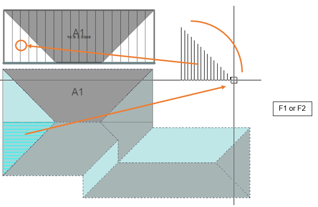
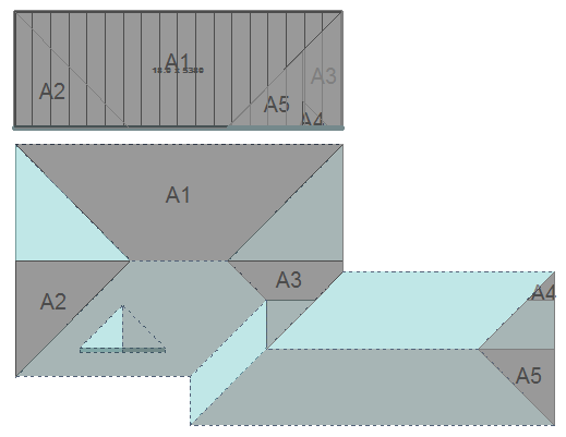
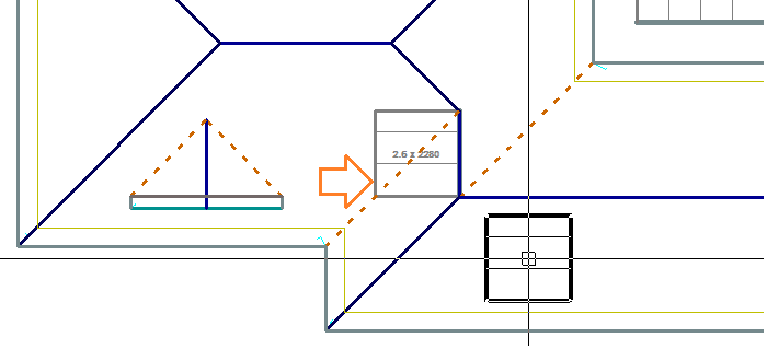
Repeat on the other side, finding the appropriate place for block-piece A3 by using rotate until that block-piece fits.
Split the hip end at the right using Split Plane at Point, so that two areas are created to reveal A4 and A5,
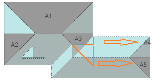
Now assign the 2 planes that were just created to Block A as A4 & A5.

Now that all of block A has been filled, we must define a new block which will be block B. Select the plane area that will define block B; select the right hand edge to stretch, and stretch the edge as shown, using the middle mouse button to snap to the corner.
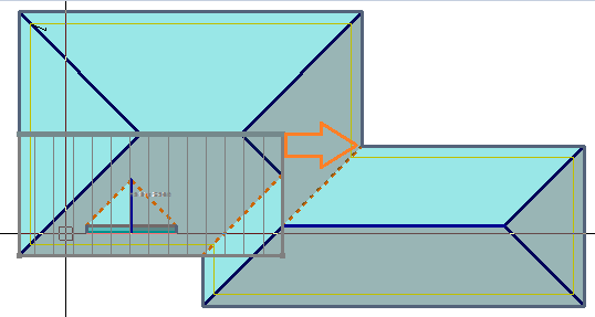
Right click to cancel that operation (assuming that you stretched it correctly), and move the block to a spot outside the roof area so that block-pieces can be assigned to that block.
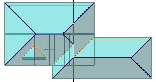
Once that is done and the Block-Cutting dialog box comes back up, click [>] at Block Letter to increment it to the next letter or R to reset it back to A, with Block Number Clicking [>] takes it to the next number or clicking R takes it back to 1. With Block Colour clicking > takes it to the next colour in the pallet or clicking […] lets you pick any colour in the colour table that you have set up.
Assign this block to be “B”
That gives us B1 & B2 which are obvious. Then split the planes as shown to give us B3 and then assign block-pieces B3 and B4 to the block. Next, move block-piece B5 onto our block.
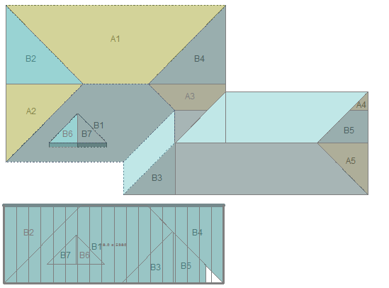
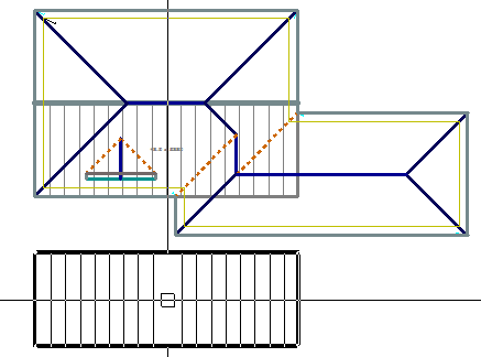
Split the planes on the dormers at the bottom of the valley. And Assign those as B6 and B7. Then move the block-pieces B6 & B7 onto our block B.
Then define a new block which will be labelled C.
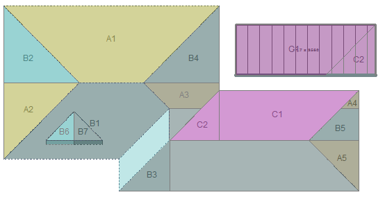
Continue this process for each subsequent block, splitting and assigning until they are all accounted for.
In the case of the small hip/valley (where E1 and E2 will be placed) don’t have a point to snap to, so scroll zoom in and select a point close as you can to the valley.
Select extend edge and then click on one of the block lines then snap to the top of D2 and B1 depending on which edge you started on and then repeat on the other side.
Stretch the edge back to the apex of the hip and ridge by snapping to the apex point. Then stretch the outer edge and snap to the geometry on the valley.
Can now move the block out and insert the remaining corners to create E1 and E2.
Note: If you have jumped in an out of the Block-Cutting dialog it is possible that the software has lost track of which block you’re trying to associate with which roof plane. Use the Cut Plane Option – Select Block before you select Assign Planes to Blocks to get yourself back on track.

After all Blocks have been accounted for, you can use the function Place/Move Legend to annotate the Block-Cut drawing with the summary of the cutting list – for example:
Note that this shows fractions of sheets. This can be adjusted to round-up to whole numbers of sheets by changing the settings in Estimate > Allowances.
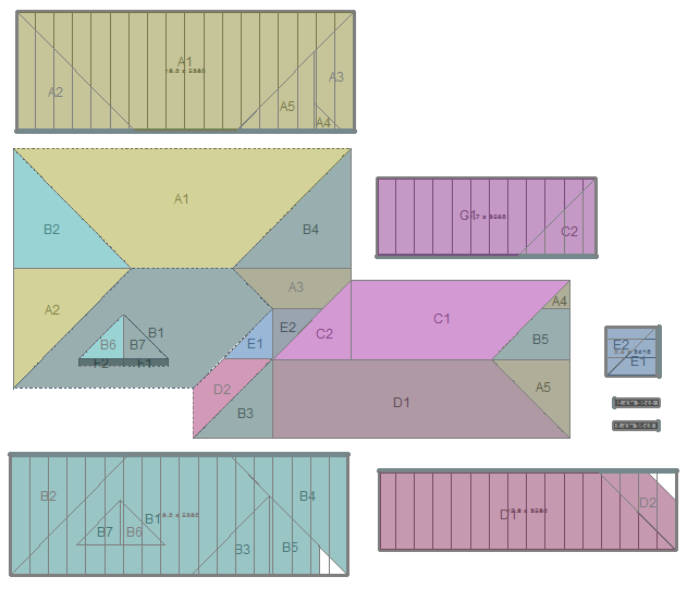
Then to finish it off 2 straight sheets for F1 & F2 on the front of the dormer.
Using Estimate > Tally-Blocks we see the correct cutting list and optimised for re-use of the waste – just 2.93%.
This method takes some adjusting to but after many years of using this exact same process manually, most roofers will find this interactive process for generating what they currently do with coloured pencils, a real bonus.
It shows the estimator that everything has been accounted for and the automated report is then available for the installers as well.
Block-Cut Output
The Block-Cut template for MS Word creates the required report for your installers. The template for this is in the ..\User folder. Refer to Templates and Key Text Strings for more details.
Comments are closed.