2D Roof Design

2D Roof Design > Track Lines
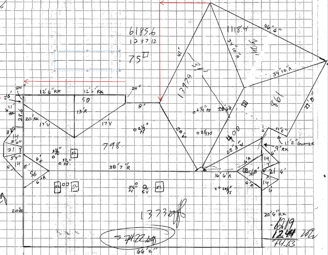
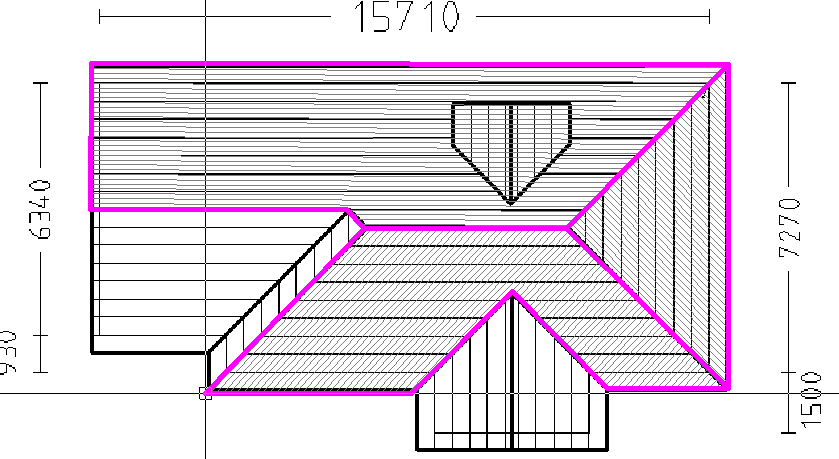
Inserts lines in 2D that are in the XY plane, with the Track command. This process has been designed to allow you to quickly and efficiently enter the outline of the wall or roof based on measured lengths only; typically when site measurements and a rough roof sketch are supplied such as the example below, which is not to scale and a representation only. Indeed, using the measurements only an accurate 3D model is not possible. However, once the 2D geometry is created, the results are reported as if they had been created in 3D.
You can switch between inserting actual lengths (what we call Tracking) and digitising freehand or constrained. You can override the constrain values by holding the Ctrl key down as you digitise.
Once inserted, the lines need to be ‘tagged’ with their respective category of ‘ridge’, ‘hip’ or ‘valley’ etc. using Tools > Change Line Type.
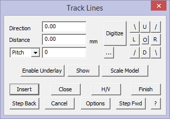
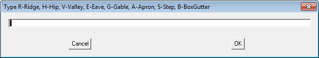
Select the function and the Track Lines dialog is displayed.
![]()
Note: The dialog box shows two fields labelled as Direction and Distance. The direction is a cardinal bearing starting at 0o – UP the screen, clockwise through 180o – DOWN the screen, and back up to 0/360o. The distance simply relates to the length of the eave/wall.
The accelerator buttons on the right hand side, are predefined directions with the following values:


![]()
Note: You can also use the letters U, D, L and R in the distance field to quickly get up, down, left and right directions. For example, you can enter R5000 or R5M in the distance field to get a eave/wall line length defined as right 5000.
You simply click the appropriate accelerator button, enter the distance and a new wall segment is drawn on the screen. You can enter a new wall by selecting the Enter key or clicking the Insert button.
If you make a mistake with a value, click the Stepback button. You can undo a Stepback operation by clicking the Stepforward button. You can step forward as many segments as you stepped back.
When you have finished locating the wall lines, click the Close button. This displays the Select the close method dialog which helps you select the type of close method you want from the current line end point to the first digitised point. This will then display the Close dialog box from which you select a close method. You are then returned to the Wall Direction and Distance dialog box.
Direction Option
The direction option is tied to the notion of Up, Down, Left and Right, but instead of using these you use a bearing angle as suggested above, up = 0° and down = 180° etc. This permits you to insert wall directions that are not square.
Distance
The distance is the length of the line in the direction specified and the units of measure are determined by the settings you have selected under Preferences – either metric or imperial units.
As a time saving device, enter the letter “U” for up, “D” for down, “L” for left or “R” for right, in front of the length of the wall or eave line required. Then click enter.
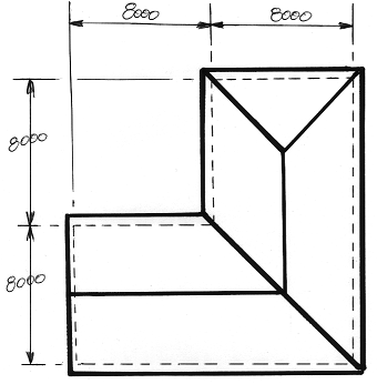
On this job, you could have typed in U8000 {Enter} R8000 {Enter} U8000 {Enter} R8000 {Enter} and then Close the outline as a Square.
You may also simply type C (short-cut for close square){Enter} in the distance field on the dialogue.
You can also input U8M indicating metres if you’re working in Metric.
Horizontal/Vertical Option
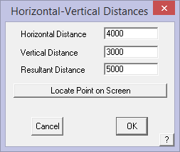
If you only know the horizontal and vertical dimensions of a wall (rather than its direction and length), you can click [H/V] button. The Horizontal-Vertical Distances dialog box is then displayed.
Horizontal distance The horizontal distance (offset) of the wall
Vertical distance The vertical distance (offset) of the wall.
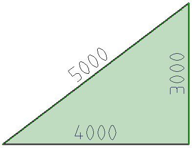
Resultant Distance This provides the opportunity for the software to do the trigonometry of a triangular situation where only two lengths are known and the software will figure the last length. If the 5000 and the 4000 length is known, the software will calculate and insert the 3000 length.
The software will flash a point indicating the likely two options for the intersection – either up or down in this case
You may also –
Locate Point on Screen to use an existing line end point as the basis of establishing the x and y (horizontal/vertical) offset from the job datum or origin. This will be automatically fill the H/V fields on this dialog. Then you insert anything different that you may need.
The wall line is drawn when you click [OK] and then you can continue entering the rest of the wall lines to complete the outline as described for Track Outline.
Using Field Measurements to Determine/Check Pitch
The distance you enter in the Distance field may also be modified by the Pitch field. If this is zero, then the distance is assumed to be a horizontal measurement. The Pitch factor is used to reduce the distance to the horizontal distance. This is typically required when the roof measurements have been collected in the field and the person measuring is running the tape up the slope of the roof. You need to reduce this to the horizontal distance.
If you do not know the pitch but have ‘up and over’ or ridge to eave measurements, you can click the […] button to the right of the pitch field to calculate the exact roof pitch.
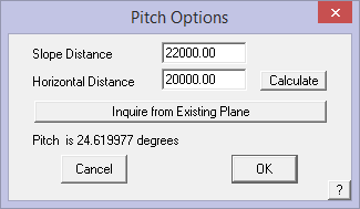
When you select [OK] on this dialog, the calculated roof pitch is inserted into the pitch field. You then use the combined pitch value and the up the slope dimension to calculate the length of the wall/eave line on the flat.
Track Line Style Options
The Options ![]() button allows you to set the line style, colour and weight for the construction lines. This is especially useful if you are digitising over aerial images and PDF plans where the confusion of the background may make it difficult to see the roof features.
button allows you to set the line style, colour and weight for the construction lines. This is especially useful if you are digitising over aerial images and PDF plans where the confusion of the background may make it difficult to see the roof features.
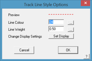
The Change Display Settings button takes you straight to the Tools > Set Display options. Saves you having to exit out of Track Outline and go to the Tools menus to set this.
Manual Construction of Geometry
The following functions allow for adding and editing lines once created, assiting you to create roof features bound by other features. Hips between eave lines and ridges equi-distant between parallel eave lines etc.
They are only accessible from the Pulldown Menu.
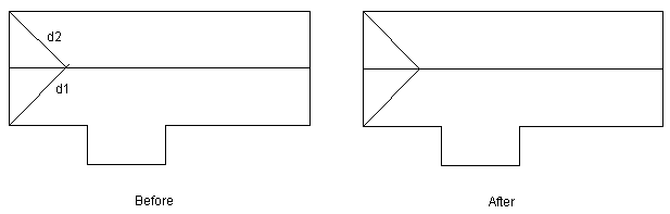
Trim Line to Entity Allows you to trim a selected line to an existing point, line or circle entity. The line is trimmed to where the normal to the line would intersect the point, or where it would intersect the entity.
This means that the trimmed line is extended to intersect with the line you select. You first select the line to trim at the trim end, then the line to trim to. You can see in the above diagram, the two hip lines and ridge lines are not connected. To connect them, use the Trim-Line and/or Trim-Corner commands.
You can see in the following diagrams, the sequence of steps to clean up the hip end
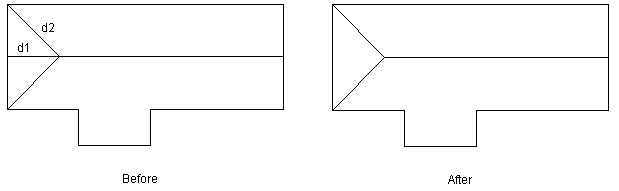
First trim the hip lines to each other.
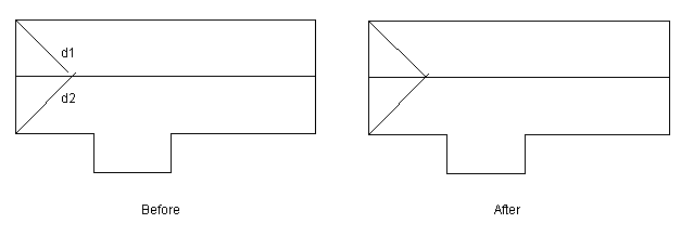
Then trim the ridge to the hip
Mirror Mirrors selected entities around either two points, an existing line or an existing plane. Selecting Num Copies = 0, it mirrors the selected entities, such as a hip or ridge line and makes no copy. Selecting Num Copies = 1 makes a copy of the selected entities about the selected axis.
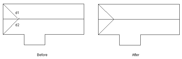
Trim Line to Corner Trims two intersecting lines to a corner. Select the lines to trim near the end that will move – use this command to trim by extending the line or trim by cutting back the line.
You first select the line to trim at the trim end to be trimmed, then the line to trim to. You can see in the following diagram, that the two hip lines can be trimmed together quite easily with the trim-Corner command.
Change Line Type Allows you to change the line type of existing lines. A typical example would be to copy a valley line because it goes the right way, then to change it to a hip..
Show/ Hide Planes Uses the Tools > Show/Hide Planes function to display the roof surface planes as they are inserted.
User Tips when Digitising
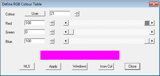
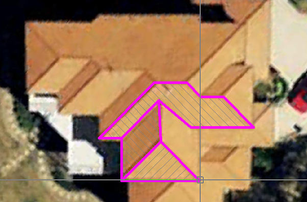
If you are digitising lots of aerial images or plans from PDF documents in 2D, you might like to change the line style so that your digitising progress is very easy to see. The line that is inserted by default (if you do not set the line type as you go) is line type None. So if you were to change a ‘None’ line to be bold and fat, you can easily see what has been digitised and what hasn’t. Use this example, under CAD > Defaults > Colour Table redefine a colour number to bright pink – let’s say colour number 21. Select Apply and Close.
Next, go to Set-Up > Preference Settings > Line Styles change the None line to the newly defined colour of bright pink colour 21 and also change the line weight to say 1.00 to make it bold.
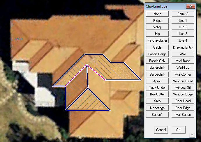
Then as you digitise using the Construct Roof > 2D Roof > Digitise Roof option, cancel the Line type definition box (shown below) by right clicking or selecting [Cancel] (which is the same thing) so that the line type is set to ‘None’, (you will then have to go back and manually select each line to redefine the line type) and the big fat pink line will be displayed instead of the regular line style for that line type.
You can very quickly see what you have completed during the process.
If you wish to keep this line style change, don’t forget to select File > Save Values and save the changes to the Values.def file (where these default settings are stored).
This works well for you both on images of planes clipped from a PDF as it does on images clipped from Google™, NearMaps™ or Bing™ or Acrobat Reader™.
Once you have competed the digitising, you then use the Tools > Change Line Type function to set the line types in turn – ridges, hips and valleys etc. This is often seen as a lot quicker by some operators
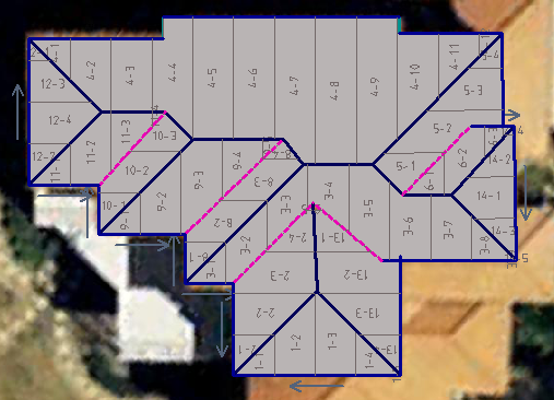
Extract brilliant metal panel cutting lists directly from the clipped aerial image or the clipped PDF drawing (subject to site inspection of course) for roofing or wall cladding.
For walls, clip the image of the wall elevation:
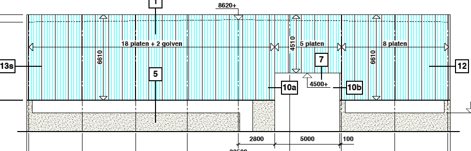
Digitise the wall (Walls > Draw Single Wall) and generate the wall panel cut list (requires AppliCad Roof Wizard module) using function Walls > Apply Wall Set-Up > Generate Wall Panels.
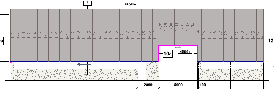
These functions will change the way you generate cutting lists in 2D – easy, quick and accurate (as accurate as the images permit).
Comments are closed.