Smartlines

Smart-Lines
By clicking on the Construct Roof > Smart-Lines icon option, the Smart-Lines options appear as described below.
Mastering the Smartlines Toolkit is the mark of AppliCad Roof Wizard user competentency – trimming lines, creating, copying, mirroring lines, inserting new roof planes – are all skills that make you a master of the Roof Wizard software.
Track Eaves
![]()
The Track-Eave function works in a similar manner as Construct Roof > Track-Outline described here. This process draws the eave lines only, leaving the rest of the roof geometry to the user to create. While this seems completely redundent for most of us (when Track-Outline does the whole thing automatically), there are some users who prefer to construct their own roof, one line at a time.
![]() While the manual construction of an entire roof is an unlikely option for most users, the ability and indeed sometimes compulsory requirement to edit roof geometry using the Smartlines Toolkit descibed below means that there will never be roof geometry that we cannot model in 3D. If it can be built, we can model it. Some of these functions require context and the best way to get that is to do the online training course at AppliCad Academy.
While the manual construction of an entire roof is an unlikely option for most users, the ability and indeed sometimes compulsory requirement to edit roof geometry using the Smartlines Toolkit descibed below means that there will never be roof geometry that we cannot model in 3D. If it can be built, we can model it. Some of these functions require context and the best way to get that is to do the online training course at AppliCad Academy.
Check Settings
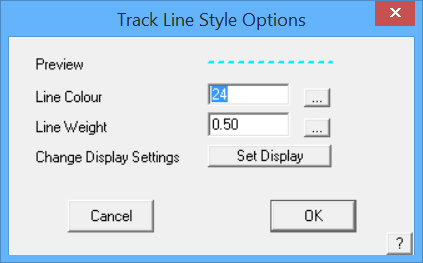
The default settings for colour, style and weight of the line are used. To change these settings go to Set-up > Preference Settings > System Preferences > Set Line Styles. You may also change the colour and style of the construction line (the temporary line that defines the outline, before roof geometry is built). Select the [Options] button in the Track Lines dialog box.
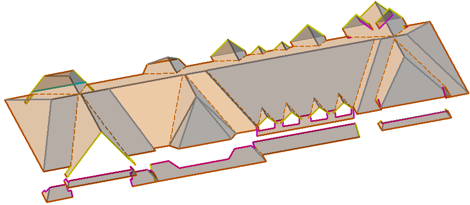
As perimeter lines are digitised using this function, each line inserted presents the operator with an option to define the line as a particular type, and with slope as required using the function keys – F1 (to make the line a hip line); F2 (to make the line a valley line) and F3 (to make it a sloping line).
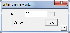
If no special attribute is selected, the line is inserted as an eave line. As each function key is selected, a dialog prompting for the roof pitch of that line is displayed – as shown below – and the line is inserted at the required pitch(es).
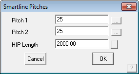
The line length is used to predefine the ‘stub’ of the hip or valley that is inserted at the corner just created.
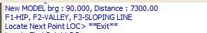
The prompt area serves to remind you what the function keys will do for you.
These functions improve digitising efficiency as most required construction lines will be inserted for you. With practice, you can half the time it takes to create most complex roof geometry using these tools.
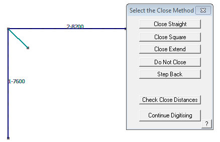
Hip or Valley stub drawn automatically by the digitise function.
 Hip End
By clicking this command you are prompted to locate the line that you want to construct the hip end on. By clicking on the required wall line the following pitch dialog appears.
By clicking [OK] a hip and a stub of ridge in the correct direction are constructed.
 Gable End
Works the same as the Hip End command but inserts a Gable end instead with the rake lines inserted at the desired pitch.
 Single Hip
Prompts the operator to select an eave line from which a hip is automatically created. Select the eave line near the end where the hip is to be constructed; the software finds the other connecting eave line. You are prompted with the following dialog box to insert a pitch for the lines, and a required length.
By clicking [OK] you are prompted to locate approximately where you want the hip to go, this is done by left clicking the mouse in the space approximately where the hip is to be created. The hip is inserted with the pitch angles defined and the length specified.
 Single Valley
This basically works the same as Single Hip but automatically changes the line type to a Valley and prompts for a pitch.
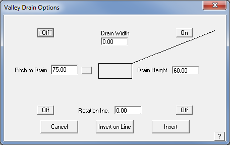
Valley Drain (Right Hand Text Menu Only) Experimental function – This function provides for a method of automatically generating a 3D graphic of a valley drain or sump, usually in conjunction with low slope roofing. Elements of the graphic can be specified before insertion onto the roof model. Once inserted, the expectation is that the valley lines will be trimmed by the operator to the appropriate roof features, usually using the Trim-to-ZLine function.
The drain and the associated valley lines are drawn using the line attributes defined under Tools > Change > Line Styles.
 Single Ridge
This basically works the same as Single Hip but the line type is a Ridge and it is input parallel to two eaves.
 Draw Roof Line Freehand
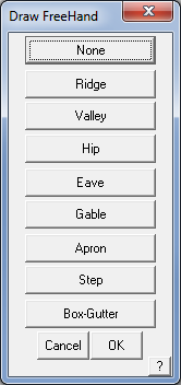
Allows you to draw free lines. You would typically use the snap function to locate the start and end points (locate with the middle mouse button) so that you are assured that a line is starting precisely at the end point of an existing line.
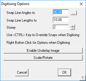
You will be prompted to set the Digitising Options that helps keep lines square and constained to tidy lengths by snapping to grids. You may also set the storey number for the line you input so that the appropriate pay scale is applied and it can be turned on and off with other parts of the roof geometry on the same storey.
Once you have drawn in each free line you are prompted to select a line type for that line. The line is then inserted using the attributes of the selected line type. If you select Gable you are then also prompted to insert a pitch.
You may also type U/D/R/L and an exact measurement in the required direction and use C to close the outline square while in this command.
 Intersect Two Plane (Intersect Pl-Pl)
The Intersect Plane-Plane button allows you to determine the location of the intersection of two planes. This is often very useful when constructing complex roof shapes one plane at a time and they need to be trimmed back to where the planes intersect. A line is automatically inserted at the line of intersection.
 Trim Line to Corner
Trims two intersecting lines to a corner. Select the lines to trim near the end that needs to move to make the new corner – use this command to trim by extending the line or trim by cutting back the line.
 Trim Line to Z Line
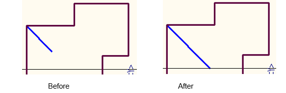
Trims a line that is at an angle to the construction plane, such as a hip or a valley, to the XZ or YZ plane of another line that does not intersect. The operator is prompted whether associated entities should be stretched with the line or stay as they are.
 Trim Line
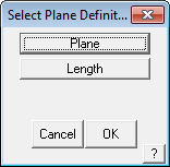
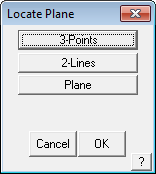
Allows you to trim a selected line to a length or to an existing plane entity. The line is trimmed to where the line would intersect the plane entity. The plane may be selected by snapping to three points at the boundary corners of the plane; two lines on the plane or selecting the plane surface hatching.
 Mirror
Mirrors selected entities around either two points, an existing line or an existing plane. Selecting Num Copies = 0, it mirrors the selected entities, such as a hip or ridge line and makes no copy. Selecting Num Copies = 1 makes a copy of the selected entities about the selected axis.
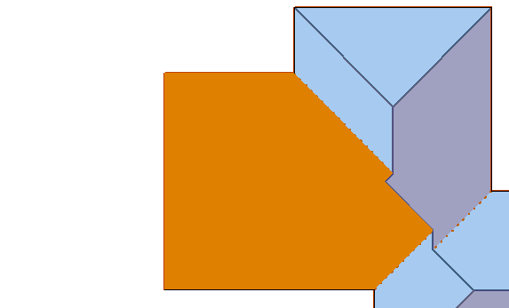
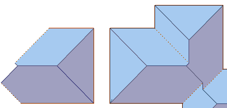
Select the entities to mirror, in this case three roof planes. We don’t have to select the individual lines since the planes are controlled by the lines, they must mirror as well. Remember to read the prompts carefully so that you not miss a step.
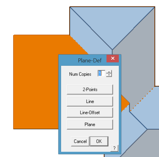
When you have finished selecting the entities to mirror, right click mouse, then you will get the Plane-Definition dialog box. This controls the method you wish to use to mirror. In this example, we will use Line-Offset. You will be prompted to select the line, then which side of the line to mirror to, then a box appears prompting for an offset amount.
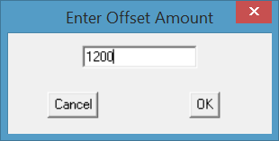
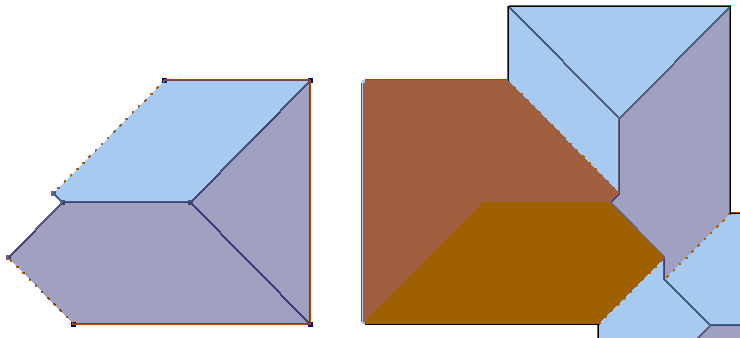
Enter the required distance between the old roof and the new roof (in this istance 1200mm).
The roof is duplicated about the mirror axis line.
 Divide Line
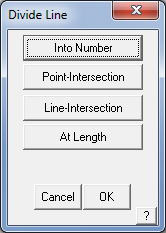
Allows you to divide a line according to various options – into a number or equal length lines; divide where a point intersects the line; at a line intersection or divides the line a set distance along the line.
 Change Line Type
Allows you to change the line type of existing lines. A typical example would be to copy a valley line because it goes the right way, then to change it to a hip.
 Auto Roof (Gen Roof)
By clicking this command you are prompted to select a wall/eave line that is connected to other lines forming a closed loop. In tracing the closed loop, if there are multiple intersecting lines at the next corner the software will automatically prompt you for the next line with a question “Use this entity?” and the lines will flash. Confirm the required line by selecting Yes. If it does not find multiple intersections, then it will automatically continue around the outline to form a closed loop of all connected lines.
Once the outline is complete the software brings up the roof style box (Hip and Valley Roof or Flat Roof), then the Roof Defaults dialog is displayed. Enter in the required defaults for Storey, Pitch etc. and click [OK]; then select any Gable Ends etc if required and click [Continue]. Your roof will be automatically drawn up using the outline as the defining entities for the roof shape.
 Plane Edge – Add Point (Pl-Edge Add Point)
Divides the edge line that defines the roof plane at a specified location. This is a surprisingly powerful function as it allows you to digitise a simple approximation of the outline, or part of an outline, and add new segment to the perimeter thus ensuring that you have a closed co-planar loop.
 Generate Planes (Gen Planes)
Will automatically generate all of the roof planes for the job using all closed loops created for the roof planes. Caution, it also generates a roof plane on the ceiling using the wall outline. You should perhaps delete this unless you particularly need it to be there.
 Flood Fill
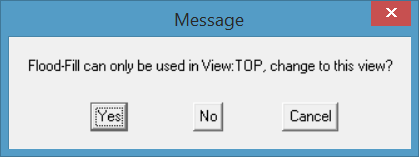
Allows you to select the centre of a collection of boundary lines for roof planes and automatically inserts the plane without the need to select the individual boundary lines. Note – Flood fill only works in Top or Plan view – you will be prompted if you are not in View Top. If you click Yes, then the view automatically changes and you may continue selecting roof planes to fill.
 Insert Plane (Ins Plane)
The operator is prompted to select a line forming the boundary of a single roof plane. The software then tracks the line through adjoining lines to find connected lines in the same plane (ie flat) until it achieves a closed loop. In tracing the closed loop, if there are multiple intersecting lines at the next corner the software will automatically prompt you for the next line with a question “Use this entity?” and the lines will flash. Confirm the required line by selecting Yes.
If it does not find multiple intersections, then it will automatically continue around the outline to form a closed loop of all connected lines. The plane is then inserted. [Continue] this process for all other roof planes until the roof is complete.
Show/ Hide Planes
(Pulldown Menu Only)
Uses the Tools > Show/Hide Planes function to display the roof surface planes as they are inserted without having to go to the Tools Menu.
Remove Geometry
(Pulldown Menu Only)
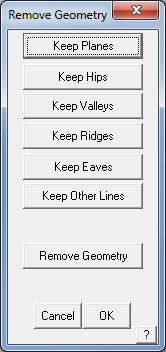
This option allows the operator to delete roof geometry based on type or category. Indicate by selecting the button, what you wish to keep or delete, and then select the Remove Geometry button, and they’re gone!
Multi-Trim Lines
(Pulldown Menu Only)
Trims multiple lines back to a reference line.
Takes the operator back to the Smart-Lines main menu.
 Move Line
Allows you to move an existing line. The selected line attaches itself to the cursor. You would typically snap (locate with the middle mouse button) the moved line to the end point of an existing line to ensure accuracy.
 Stretch Line
Allows you to move a line but the connected lines stay connected and are effectively stretched to the ne position.
 Copy Line
Allows you to copy an existing line. The selected line attaches itself to the cursor. You would typically snap (locate with the middle mouse button) the copied line to the end point of an existing line to ensure accuracy. This helps you make a lot of lines with the correct aspect very quickly and easily.
 Delete Line
Allows you to delete existing lines or planes.
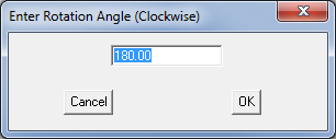
Rotate-2D
(Right Hand Menu Only)
This function copies and rotates a line about a defined point. This is handy for quickly creating roof line geometry for low slope roofs.
Right mouse click quits from any of the Smart-Lines functions
Comments are closed.