Report Templates – CAD
Report Templates – CAD
Objective: To design or customize the report templates to suit your individual needs.
![]()
Note: This section may appear to be quite a daunting process at first as it requires use of some CAD functions. We suggest you are very familiar with the workings of the software before returning back to this point.
There are two distinctly separate processes for creating report templates from AppliCad software. This help document describes both – first the CAD template (what we have used for 25 years and still support), and the seamless integration with MS Word or MS Excel for report generation.
When output reports are created by the software, it first looks for a Microsoft Word template of the required name form, for example QuotationLetter. The file it is looking for must be saved in the ..\User folder or ..\Corporate and must have the name of QuotationLetter.DOC without spaces (as in Word Document) or QuotationLetter.DOT as a regular Word Template document.
If the software finds the DOC or DOT by the defined name, it will use it. If it does not find a Microsoft Word template, it will use the AppliCad default CAD template for QuotationLetter which is saved in the AppliCad database file, RoofWiz.dab in the …\User folder. This will ensure that all your existing default CAD templates will work as they do now when the software is updated by new releases.
Creating a template in MS Word allows for more creativity in design and many operators may be more familiar with Microsoft Word than the CAD functions. The use of Word Templates is described here. Using a Word template, you can have as much or as little information as you require for your projects. If you plan to use Word templates exclusively, you might consider going directly to that section, however, a lot of useful information is described below about the process.
AppliCad CAD Report Templates
The following pages describe editing the default CAD templates stored as a subfigure in the database file Roofwiz.dab in the …\User folder.
This section is only necessary if you find that the existing reports are not sufficient for your needs, that is, if you need to add further information to a report or change the layout of a report.
AppliCad default templates are stored in a CAD database called Roofwiz.dab according to the table below. If you decide to use Word to generate your reports and output tables, each template is saved as a Word template with the same name – that is, QuotationDetails as a sub-figure in RoofWiz.dab would be QuotationDetails.DOT with Microsoft Word.
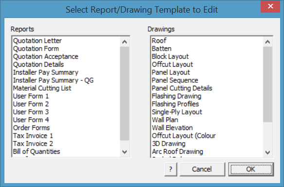
The first step when modifying your AppliCad generated report templates is to find them. The CAD Report templates can all be found by going to Tools > More…> Edit Templates. You will be presented with a box as shown below.
You will need to save the last roof job you were working on before modifying the templates as your job will be cleared to open the template ready for editing. If the job has not been saved, you will be prompted to do so.
By selecting the form you wish to modify, that template will be opened in the main screen, similar to the picture on the following page.
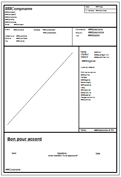
From here you can modify the template – adding line work using the CAD functions, or adding Key Text Strings [KTS] for software generated values or regular text for annotation of the report. This process is described in substantial detail below. You may also find more detail [KeyText Strings] where all the available key text strings are listed.
Template Structure
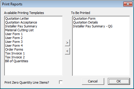
The output reports in the AppliCad software are automatically generated from the user defined templates listed above. When you click the Print button on the Reporting > Supply and Reporting > Supply and Install dialog boxes, the following list of standard reports are available to be printed.
The following table describes each of the CAD reports on the Select reports to print dialog box as well as which template is used.
:
| Report name | Template name | Intended Use |
| Quotation letter | QuotationLetter | A quotation to send to your customer detailing the information as a letter |
| Quotation form | QuotationForm | A quotation to send to your customer detailing the information in a tabular fashion. |
| Quotation acceptance | QuotationAcceptance | Same as above with the addition of a place for the customer to accept the quote with a signature |
| Quotation details | QuotationDetails | This report tabulates the materials and costs for the job |
| Installer pay summary | PaySummary | This report tabulates the labor costs for you to perhaps give to the installer |
| Material cutting list | MaterialCuttingList | This report tabulates the sheet and flashing cutting lists |
| User form 1 | UserForm1 | An extra form for you to define |
| User form 2 | UserForm2 | An extra form for you to define |
| User form 3 | UserForm3 | An extra form for you to define |
| User form 4 | UserForm4 | An extra form for you to define |
| Order Forms | OrderForm | The Supplier’s Order form. Generated for each supplier in your list of required items. |
| Tax invoice 1 | TaxInvoice1 | A tax invoice |
| Tax invoice 2 | TaxInvoice2 | A tax invoice |
| Bill Of Quantities | BillOfQuantities | A Bill Of Quantities report |
| Roof Quantities | Roof Quantities | Summary of roof geometry (areas and lengths) and a roof plan |
Linking Templates to Output
You can however create any other report template with any name so long as these names are listed in the text files called UserReportNames.csv and UserDrawingNames.csv . The software needs to know that you have created a new template, what it’s called, and how you wish to refer to it.
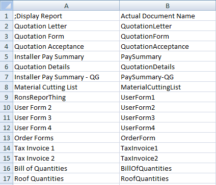
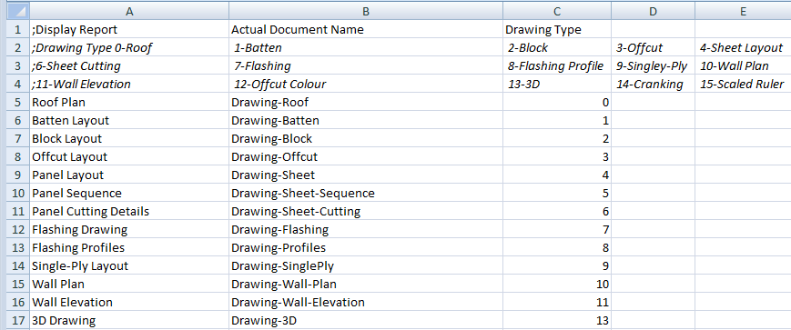
UserReportNames.csv is where the preset template names for CAD and Word/Excel Report Templates are associated with the reporting output process.. This allows any template form/report to have any name when displayed in the print options list. Column A is the name you wish to have in the [Print] options list. Column B is the actual file name in the ..\User folder when viewed in Excel.
UserDrawingNames.csv is where the preset template names for both CAD and Word/Excel Drawing Templates are associated with the drawing output process. This allows any template form to have any name when displayed in the print options list. Column A is the name you wish to have in the Print options list. Column B is the actual file name in the ..\User folder. For drawing output as distinct from report output, you need to tell the software what sort of drawing it is so that th ecorrect information is automatically included, without you having to do any further work in generating the report. This is done in column C using the code number as required.
Once a new template has been created, and saved to the …\User folder, it can be added by simply going to the Tools > More > Edit User Templates option.
The complete list of both CAD templates and Word/Excel templates is displayed.
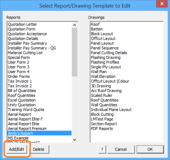
To add your new Word template to the list, select Add/Edit and the Edit Report dialog is displayed that provides for you to add the new report name (as you want it to appear in your print options list) and then select the name of the actual template file (for Word or Excel) or subfigure name (if it is a CAD template).
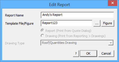
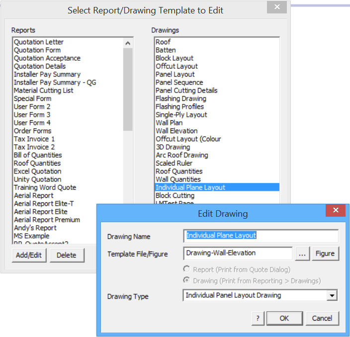
Select [OK] and the new report template is linked and available in your print list. If it is a drawing template, the extra option is displayed to set what type of drawing output you require.
Creating and Modifying Templates
When you look at one of the templates, you will notice that it comprises line work, text labels, text strings with a prefix of ### and possibly a diagonal line. To select a report template to edit, go to Tools > More… > Edit User Templates and select the report from the list displayed
Modifying the Template Text
Insert Key Text Strings
Once we have decided what our template is to look like, we start adding or modifying text on our template. It is recommended that the best way to develop your skills with creating templates is to try to replicate the reporting process that you currently use. This has shown to be a great way to get going with a process that can be complex at times.
There is what we call regular or normal text and key text strings. Key text strings (KTS) are actually commands interpreted by the software that are ‘embeded’ into the template. The software identifies the subject of the key text, finds the detail in the job and places that detail into the template in the place of the key text.
Selecting the appropriate key text is made easy by the key text string selection dialog box.
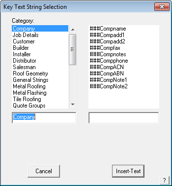
Go to the function Tools > More… > Modify Text > Insert Key Text from the Pulldown menu and the Key Text String (KTS) dialog is displayed.
From the KTS selection dialog box you can insert a text field that is linked to the appropriate information in the model database. Therefore if you put in the ###Compname field, when you print up your reports, the Key Text String (KTS) will be replaced by the company name for the quote. To show the fields on the left of this dialog box, click on the down arrow at the end of the field.
From here you can select category, and the KTS from that category will appear on the right hand side of the dialog box. To insert the KTS, click on the KTS that you want to insert and then click on Insert-text. You will then be asked where you want the text to be placed. Move the pointer to where you want the text to go and left click the mouse. The KTS will now appear on your screen.
A list of all of the Key Text String’s is found in the back of this manual. A KTS exists for every variable and data table that you are likely to need. There are dozens of Key Text Strings covering every conceivable bit of information to do wth roofing and estimating.
It is recommended that the best way to develop your skills with creating templates is to try to replicate the reporting process that you currently use. This has shown to be a great way to get going with a process that can be complex at times.
Select the text string that you need and place it on the template. The text style, size and position is determined by the style etc of the Key Text String so this needs to be checked too.
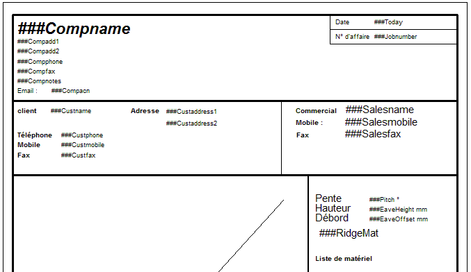
Regular or normal text – no ### signs Key Text String – with ### signs
The key to preparing a good report and submittal drawing is to know exactly what information you want to show on the report, and where you want it to go, before you start editing.
Key text strings can be also recognized even if they are embedded in another text string. For example, you may enter the following as a text entity:
Dear ###CustName,
The price for your job is $###JobTotal. Thank you for the opportunity to quote your job, etc.
This overcomes the problem of having to space the regular text label that you want and the key text string variable.
Insert Normal Text
The next item on our Tools menu is Ins-Text. Click this command and the following dialog box will appear.
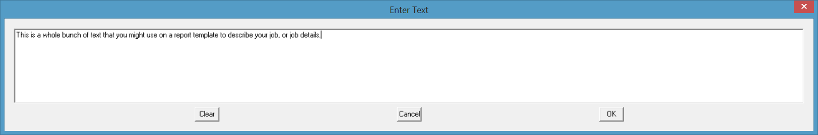
From this dialog box you can insert your own normal text that annotates the report. Type in the text that you want to put on the template and then click [OK]. You will then be asked where you want to put your text. Move the cursor to where you want your text to go and left click the mouse. Press the right mouse button to exit the placement stage, and you will be brought back the previous dialog box. If you would like to add in more text simply repeat the process previously explained. If you would like to exit simply click on [Cancel].
The next item on our Tools menu is Text-Defaults. Clicking on this command will bring up the following dialog box.
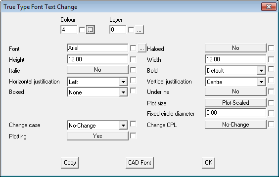
In this dialog box we have a number of choices setting the presentation of the text. Bear in mind that any changes that are made in this dialog box will stay as the default for any new text that you may put in. For this tutorial we are only going to go through the basic functions of this dialog box, these are Colour, Font, Height, Italic, Boxed, Horizontal Justification, Bold and Underline.
The first of these commands that we will use is the colour function. Click on the selection box after the colour field, and a colour palette will appear, select the colour that you want and then click [OK].
The next field we will change is that Font field. To change this, click on the selection box at the end of the font field. This will bring up the following dialog box.
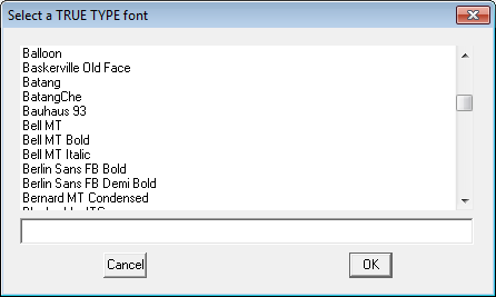
From here select the font that you want and click [OK].
We will ignore the x Offset field, and move on to the height field. This field is where we set the height of the text, the larger the number the larger the size of the text. To change this field, click on it and type in the size that you want.
The next field we come across is Italic. Changing this to yes will put the text in Italic. To change this click on the box to change it from Yes or No.
The next field we come across is the Horizontal Justification field. This command is used to describe where the text will be written from, for example, the text will write normally. The text will write from left to right across the screen. Or, stay centered on a particular point. To edit this field click on the arrow at the end of the field. This will open up a drop down menu with 3 choices in it Left, Center and Right. Move the highlight down to the choice that you want and click on it. The menu will close and the choice you made will be left in the field.
The next field is Boxed. This field uses a drop down menu, in which you can put a border around the text if you want to. If you do not want to put a border around the text leave this on None.
We will skip the next three fields which are Haloed, Y Offset and Width, and move onto Bold. This field also uses a drop down menu setup, in which you can alter the boldness of the text if you want to.
Underline, is the next field we come across. Selecting Yes in this field will put an underline on the text. If you don’t want this, leave this on No.
The remaining fields we will ignore for the time being. (You may wish to read further about this in the online CAD manual mod44.pdf).
To save these fields as your default click on [OK], and the settings will be saved.
The next command that we come across is Change. Clicking on this will bring up a dialog box similar to that of the Text-Defaults dialog box. The main difference with this command is that it will only change the text for the text that you select. Make the changes in the appropriate fields and then click [OK]. You will then be asked which text you would like to change. Select the text and right click the mouse. The following dialog box will then appear
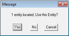
If you have chosen the correct text then click on Yes. If you have not then click on No, and reselect the correct text.
The next command that we come across is Move. Click on this command, and you will be asked to select which text you would like to move. Select your text, and move the cursor to where you want the text to be moved, you can snap to a point. When your text has been moved to the correct location right click the mouse. If you don’t want to move any more text right click the mouse again.
The next command that we come across is Copy. Click on this command, and you will be asked to select which text you would like to copy. Select your text, and move the cursor to where you want the text to be copied to. When you have finished copying your text, right click the mouse. If you don’t want to copy any more text right click the mouse again.
The Next command that we come across is Edit. Click on this field and you will be asked to select which the text that you want to edit. When the text has been selected type in what you would like the text to be, and click [OK]. This will change the text to what you have written. If you have chosen the wrong text, or want to exit click on [Cancel].
The final command is Delete. Use this command to delete any unwanted text. Simply select Delete and you will be asked to select what text you would like to delete. Select the appropriate text(s), and then right click the mouse. The following dialog box will appear:

If you have selected the correct text then click Yes, and the text will be deleted. If you have chosen the wrong text click No.
That completes the section on how to edit the text on your templates.
Modifying the Layout
You might want to edit the layout of the template, change the line borders or text boxes or to have the roof plan inserted onto a template. To add the roof plan you must draw a diagonal line that sets the extents of the roof plan picture on either layer 999 or layer 990. Layer 999 draws the roof plan; layer 990 draws a flashing drawing.
To modify the line work, select CAD from the main menu followed by Line. This will bring up the following menu.
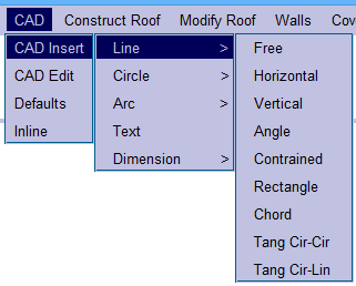
From this menu we will only need to use 6 commands. These commands are Insert, Edit, Move and Delete. The first of these commands that we will use is Insert. This command will bring up the following menu.
From this menu we will yet again only use a few commands. These commands are typically Free, Hor, Ver, and Constrain.
By selecting Free you can draw in a line using the cursor anywhere on the screen, with no set length or angle. When you have drawn your line right click the mouse to exit this command.
The next command is Hor. This command will allow you to draw a horizontal line anywhere on the screen, with no set length. To draw in you line move your cursor to where you want your line to start and left click the mouse. Then move your cursor to where you want your line to end, the angle of the line doesn’t need to be perfect as the program will draw a perfect horizontal line. As before, right click the mouse to exit this command.
The next command is Ver. This command works exactly the same as the Hor command but will insert a vertical line instead. The next command is Constrain. This command will allow you to draw in lines of any length, but you can set a constraint on the angles,(i.e. 45).
The next menu option that we come across in the CAD Edit > Trim. Selecting this option will bring up the following menu.
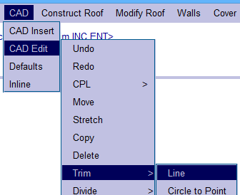
From this menu we will only be using the one command, which is Line. This command will now allow you to trim a selected line to a point intersecting another line. In other words you can trim two lines to make a perfect corner. To do this first select the line that you would like to trim, making sure that you select closer to the end that you would like to be trimmed otherwise the line will be trimmed from the wrong end causing generally an extremely short line. When you have selected the line, select the line that you would like the first line to be trimmed to, and your line will then be trimmed to the second line.
To exit this command simply right click the mouse.
The next menu option that we come across in the CAD Edit > Move. Using this command you can move an entire line to anywhere on the screen. After selecting this command you will be asked to select the line that you would like to move.
Select the line that you would like to move, taking note of where on the line you selected as it will take the end closest to where you selected as the reference point as to where you place the line. When the line has been selected, move the cursor to where you want the line to start and left click the mouse. You can continue moving this line if you wish by continually pressing the left mouse button. If you are happy as to where the line is you cancel the placing of the line by right clicking the mouse. If you don’t want to move any m ore line you have to right click the mouse again, because the software will be asking you to select the next line that you would like to move.
The next menu option that we come across in the CAD Edit > Delete. This command is used for deleting line(s). Simply select this command and you will be asked which line(s) you would like to delete. Select the line(s) that you would like to delete, and right click the mouse. This will bring up a similar dialog box to the following:

If the selected lines are correct, select Yes, and you line(s) will be deleted. If they are not, select No. and reselect the correct lines. The next menu option that we come across is the CAD Edit > Change. This will bring up the following dialog box.
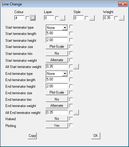
From this dialog box you can change the style, colour and thickness of a line. To change the colour of the line click on the selection box at the end of the colour field.
This will bring up the following dialog box.
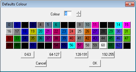
From this dialog box you can select the colour of the line that you want. To do this simply select the cour that you want from the pallete, or type in the corresponding number. When you have chosen the correct colour click on [OK], and you will return to the main dialog box.
The next command we will use from the main dialog box is Style. This will change the style of the line. Click on the selection box at the end of the Style field and the following dialog box will appear.
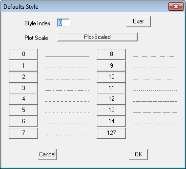
From here you can see all the types of line that you can use. To choose a line simply click on the number next to the appropriate line or type in the number. When the correct line has been chosen, click on [OK], to return back to the main dialog box.
The final command that we will use on the main dialog box is Weight. The command is used to change the width of the line. Clicking on the Weight selection box, will bring up the following dialog box.
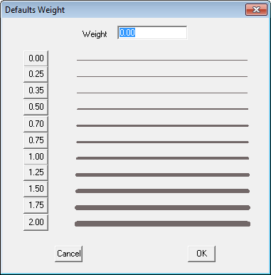
To change the thickness of a line, click on the number corresponding to the appropriate thickness, or type in the number. When the appropriate thickness has been chosen click on [OK], and you will be returned to the main dialog box. Now that all of your specifications have been entered, click on [OK] and you will be asked to select the line(s) that you would like to change to the specifications that you have just set. One the appropriate line(s) have been selected, right click the mouse and the following dialog box will appear.

If the line(s) that you have selected are correct click on [OK], and the line will be changed. If the lines are not the lines you wish to change, click on No, and reselect the line(s) that you would like to change.
The final command that we will look at in the CAD Edit > Defaults. Clicking on this will bring up the following dialog box.

This dialog box is identical to the one under Change, but the only difference is that any changes you make in this dialog box will be saved as your defaults. Meaning that every time that you open the Change dialog box whatever the figures that you entered into this box will be the figures that will be in the Change dialog box.
Ins-Logo This command allows you to insert your company logo onto your template. The logo must be saved into your USER directory and be an image file. The best formats are, JPG, BMP and TIF.
Text-Defaults This command lets you set the defaults for text insertion.
Change-Text This command lets you change the appearance of an existing text entity.
Move-Text This command lets you move a text entity from one location to another.
Copy-Text This command lets you copy a text entity from one location to another.
Edit-Text This command lets you edit an existing text entity.
Delete This command lets you delete an existing text entity from the model.
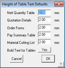
Set-Text-Height This command lets you set the text height for tables which appear on 5 separate reports.
Set Text Field Width This option allows you to define the text width for notes text and other width definable text on reports. This edits the template for the report.
Make-Text-Float This command allows you to make text “Float” so it is not moved by other Key Text Strings. Mainly used when setting up Quote Group templates.
Comments are closed.