Openings
 Openings
This command lets you insert door and window openings into a selected wall. You may also create a library of pre-defined windows and doors.
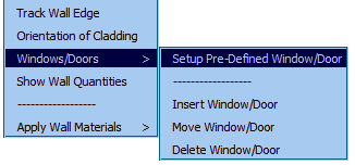
Select Walls > Window/Doors > Setup Pre-defined Window/Door.
The following dialog is displayed. Type in the required description, indicate whether it is a door or window and the required opening size and then click Add. This creates a new opening item that may be used on your job.
Typically you would define the sizes of your favourite supplier. Once they are defined, you don’t have to do it again.
The Select button allows the operator to select an existing definition to modify or copy.
Delete removes an opening definition from the list.
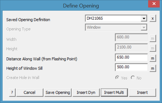
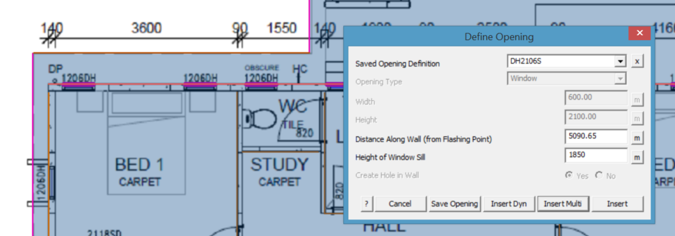
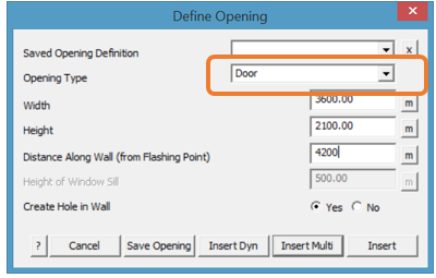
After you select the wall line at the base of the wall that requires the opening, the Define an Opening dialog box is displayed. You can select from a list or define a one-off opening.
Saved Opening Select the button next to the field and your list of windows and doors will be displayed. Select the required one from the list.
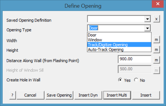
Opening type This toggles between Window and Door. A door will always be inserted from the base of the wall.
Distance along the wall The distance from the end of the wall line to the near side of the door. Notice that each of the distance fields have a [m] measure button next to it so that you can measure the distance or length of an opening on an underlay image while digitising.
For a door, you see the following parameters:
Width of door The width of the door.
Height of door The height of the door.
For a window, you see the following parameters:
Height of window sill The height of the window sill
Width of window The width of the window
Height of window The height of the window
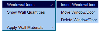
After you enter the parameters, click Insert to insert the opening. If you make a mistake, you can click Undo to delete the previous opening. You may also select Delete Window/Door from the Pulldown menu.
The Move Window/Door option allows the operator to move an opening in the wall plane. The selected wall is displayed on its own in the construction plane and the opening may be dynamically moved. The coordinates from the lower corner of the wall are displayed in the top left of the working area of the screen. You may also move an opening from one wall to another.
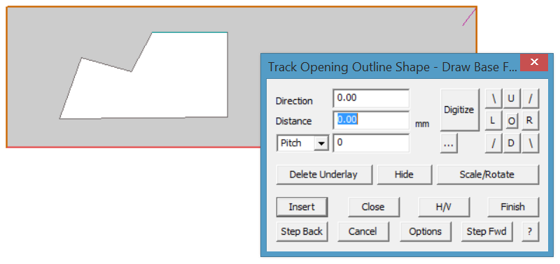
Openings may also be inserted by ‘Tracking’ or ‘Digitising’ the outline of the opening in the wall such as an architectural window feature, or Auto-Tracking an existing line, circle or curve on the wall.
For example:
Insert Openings in Dynamic Mode
Windows and doors may also be inserted in Dynamic mode – [Insert-Dyn]. In this mode, the described window/door is attached to the cursor while the workspace is flipped into the plane of the selected wall.
The window/door may be placed by sighting it against other features.
While in ‘Dynamic’ mode – you may also use the inline functions to place the window/door using precise measurements. When prompted to place the window/door, the crosshair cursor is displayed, move it up to the pulldown menu and select [CAD > Inline] and the most appropriate function for what you are doing from the options that include ‘reference point’, ‘mid-point’ or ‘distance along’. Follow the prompts and place the window/door at the required location.
When you are finished inserting openings, click the right mouse button to [Cancel].
Alignment of Openings
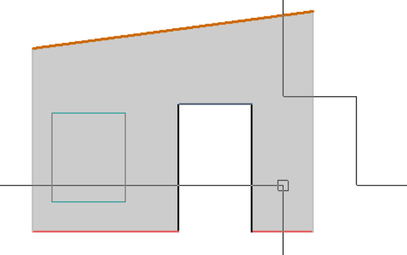
If the bottom of the wall (line selected) is not level, then the window sill simply follows the direction of the reference line.
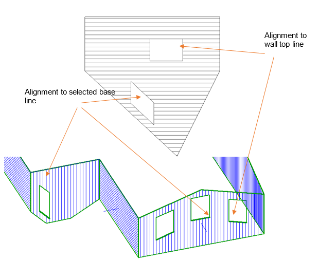
The window or door will also align with a top edge as well. For odd shaped walls, the wall may be re-drawn using the Track-Wall-Edge function described above. The line is automatically tagged Wall-Top or Wall-Bottom as appropriate. Openings will automatically align to these wall line types.
If the gable end has been inserted using the Add Gable End command, you will have to change the line type to Wall-Top to add the window or door aligned with that line. Use the Tools > Change-Line-Type function to achieve this. Often it is easier to select the wall lines to align with in the ISO view. The software will then switch to the appropriate view for positioning the opening.
The lines describing the openings are automatically tagged as Door-Edge, Door-Head, Window-Edge,
Multiple Openings
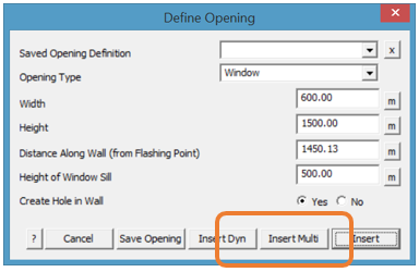
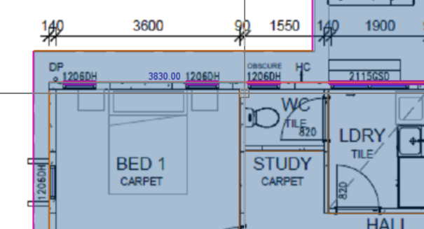
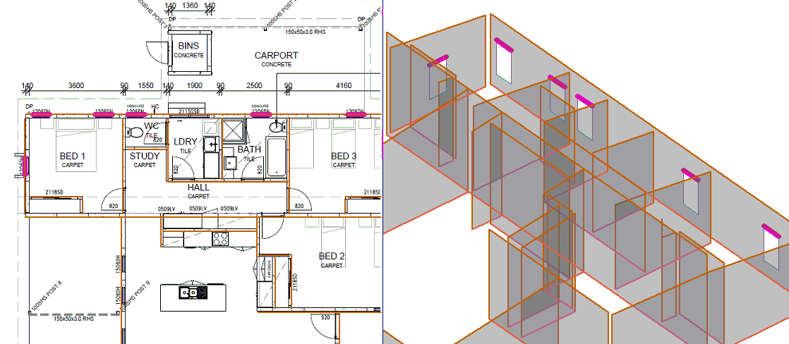
If you have to insert a few windows or doors along the same line, such as we do along the back wall in our example, use the option [Insert Multi] on the dialog box.
Select the openings command, select the wall line to attach to and then set up the correct size a sill height for the window, (or select from a pre-defined window). Then start placing your openings along the wall one after the other.
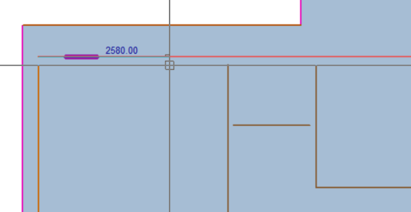
In Plan view, the user gets a distance measurement displayed along the wall.
Distance to edge of each opening…
Distance to edge of next opening…
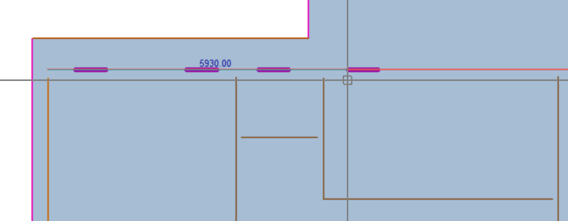
And so on.
When the wall has all its openings, cancel that wall (right mouse click), select a new wall and go again until all openings have been installed on each wall.
The same process is applied to inserting a door in a wall. Select opening type to be door or select from pre-defined doors saved previously. It is useful to work in split screen mode for doors as well.
No Hole
In some situations, wall panels are cut on site to suit the structure, essentially the hole for the opening is waste material. For this situation, select the option Create Hole [No]. The window or door is shown, but the wall cladding is not removed.
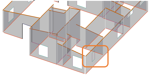
Window shown in position without the hole being cut out.
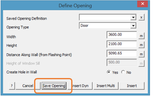
Defining Windows and Doors
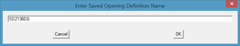
If you have a regular supplier of windows and doors, it is very effective to have these predefined as has been discussed above. When you define a new window or door, select the [Save Opening] button and you will get a dialog displayed to give the opening a name. Use a name that will be easily recognised by all users and select [OK]. The definition is saved and ready to be used again and again.
Comments are closed.