Linear Nesting
 Linear Nesting
This process takes all panels from the roof, orients them with respect to lap direction and sequentially adds them together to form a single, continuous length of coil material. From the panel sequence list, individual panels are derived which form the basis of the cutting list.
After you confirm that you want to nest the sheets, the Linear Nesting defaults dialog box is displayed.
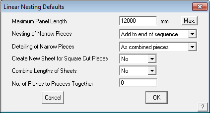
Maximum sheet length This length then determines the order of the sequence. As you reduce the maximum length, the amount of waste increases. Also, pieces longer than the maximum length are not modified. The default length you are presented with is the one associated with that profile when you created it (see Set-Up > Metal-Panels). If you enter zero (0), then the process ignores a maximum sheet length. If you set the length to be very small, then you get a result similar to Tally-Panels. Note however, that Tally-Panels does not take overlap into account.
Max. This button permits the longest sheet to be calculated by the software from the roof model and displayed for the user. This will help determine the optimum maximum panel length for the job.
Nesting of narrow pieces Here you choose to either combine the narrow pieces into the nesting or ignore them, and simply add them to the end of the coil.
Detailing of narrow pieces If you choose to add the narrow pieces to the end of the sequence, you can nominate how you have them annotated. You can have them annotated collectively or individually.
Create New Sheet for Square Cut Pieces This option provides controls for bundling panels into more manageable packs and may be used in conjunction with the following option.
Combine Lengths of Sheets This option provides controls for bundling panels into more manageable packs.
No. of Planes to Process Together forces the software to nest within a range of adjacent planes. This reduces the opportunity for the software to nest a piece from the opposite side of a roof requiring the installer to carry it across the job.
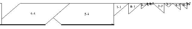
The following diagram shows you the end of the sequence and the narrow pieces simply added to the end.
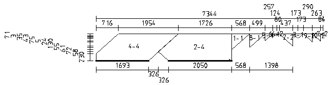
If you incorporate the narrow pieces in the nesting process, then you get a result similar to that below.

If annotated collectively, you get the following result.
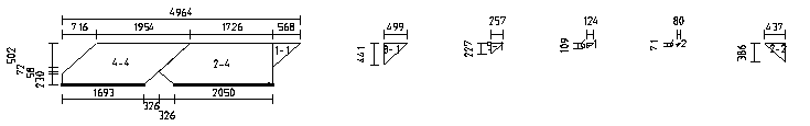
If annotated separately, you get the following –
During the process, you see the generation of the panel sequence diagram and the panel detail diagrams. After the process these diagrams are saved in their own files and the dimensions that have been automatically inserted may be moved to tidy up the appearance of the output.
You can see the panel sequence diagram in the model called RW-Sheet-Sequence in the same database as the roof model. The entire panel sequence is automatically broken into smaller strips ready for it to be printed on A4 and letter size landscape format at a scale of 1:100. The entire sequence may also span multiple pages.
You can see the panel cutting diagrams in the model RW-Sheet-Cutting in the same database as the roof model. The individual panels are automatically positioned to fit on A4 and letter size, drawing at a scale of 1:100.
As part of the process, a PCF (Piece Coordinate File) is written detailing the coordinate perimeter of each piece on each sheet. Refer to the appendix for the format of the piece coordinate file. The actual name of the PCF file is <databasename>.PCF
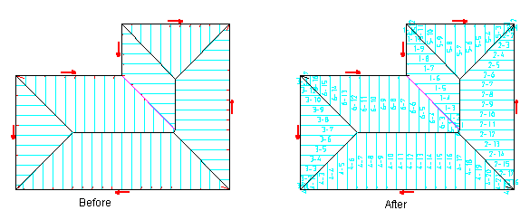
Linear Nesting is performed by the software by calculation of how sheet cuts can be optimised using the seam/lap side. To define seam/lap sides in the software, you do this by inserting lap direction arrows. These arrows can be modified by simply selecting the Swap-Lap-Direction button and then clicking on the arrows that define the lap direction. Once inserted, the software will then nest the sheets according to these seam/lap direction arrows. If no lap direction is defined, the software simply takes each panel and places it into the nesting schedule, but does not allow for any rotation of sheets as it does not know which side the seam is on. As a result, very little successful nesting will occur compared to what would normally be expected.
If the lap directions are inserted in the way in which a roofer would normally lay out a roof, then the linear nesting will be much more successful, because the lay directions on a simple hip configuration, for example, will result in almost zero waste, when compared to laying out the roof in a haphazard manner.
The following diagram shows the annotation of the metal panels on the roof.
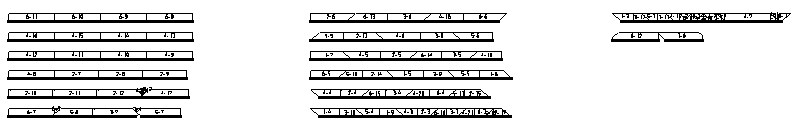
The panel sequence drawing is pre-processed to fit on A4 and letter size reports.
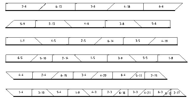
A close up of one page shows the annotation and sequence of the panels more clearly.
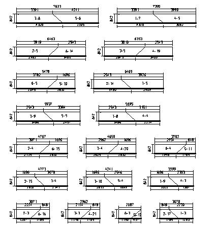
The cutting details are also preprocessed to fit on A4 and letter size reports.
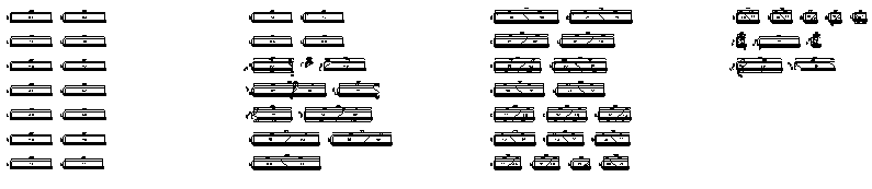
An enlargement of one page shows the annotations and dimensions for the nested sheets.
The cutting list sequence is modified by selecting those sheets with the minimum sequence number.
Gen-Panels ‘Show’ Options
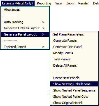
These options (available only from the Pulldown menu) allow the operator to review the Nesting Calculations, the nested Panel Sequence and the nested Panel Cut drawings without losing the model.
Once you are satisfied with the output displayed, select Show Original Model to bring the job back with the panels drawn according to the definitions used. These reports may be printed from the Reporting > Print Drawings menu.
Comments are closed.