Dimension Roof/Wall Options
Dimension-Roof
This command displays a sub-menu which allows you to add dimensions to the roof automatically or manually.
 Insert-Auto
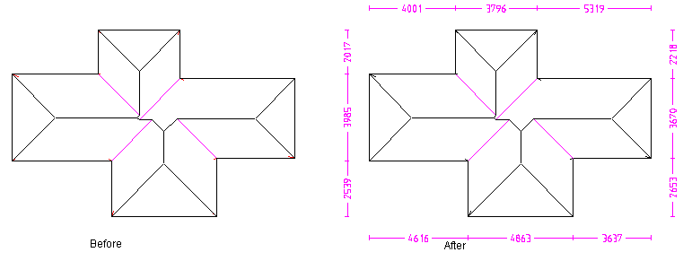
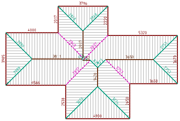
This dimensioning command inserts dimensions automatically around the outside of the roof. Running dimensions are automatically inserted along the top, right, bottom and left hand sides of the roof model.
The following diagram shows the perimeter dimensions.
This button is a ‘toggle’ button – select it once to insert dimensions, select again to delete them.
 Insert-Pnt-Pnt
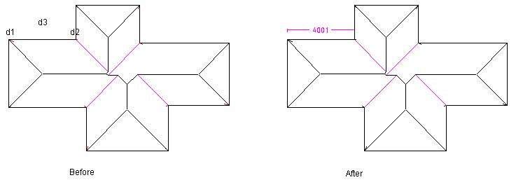
In this case, you first locate the two points you wish to dimension, usually by ‘snapping’ then using the middle mouse button, followed by the position for the dimension.
 Insert-Line-Line
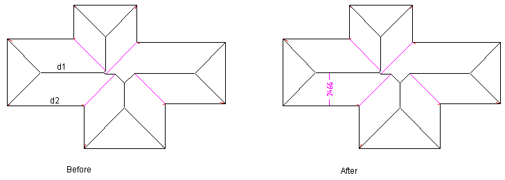
In this case, you first locate the two parallel lines you wish to dimension between. The dimension will represent the 3D distance from the first line to the second line. The position of the dimension is determined by the the point where you selected the first line. You would use this dimensioning command to detail the rafter length on a roof plane. Note that if the lines you select are not parallel, the dimension is not inserted.
If the lines you want to dimension between are boundary lines of 2d-roof planes (created by 2D Design), then you will get the 3d distance reported.
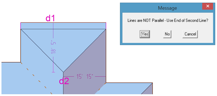
If this function is used on the eave and ridge line of a hip end, the apex will be used to determine the dimension. Select the eave line first (d1) as this sets the position for the dimension. Then select the ridge line. The reminder message is displayed, giving you the option to accept the dimension, in case you selected lines in error.
 Roof Line Lengths
This command annotates the dimension of each roof line (except for aprons). The dimension is rounded to the nearest mm (or ¼ inch) and truncated. The colour of the dimension text may be set to be the same as the line associated with it. Tis aids in reading the dimensions. This is set under the Dimension Defaults. They can also be set to be a distance away from the associated line to aid in the reading.
This button is a ‘toggle’ button – select it once to insert dimensions, select again to delete them. You can also set the length below which, no dimension is inserted – you do this under Set-Up > Preference Settings > Dimension Defaults. It helps to ‘de-clutter’ the model.
Reposition Dimension
(Pulldown Menu – Tools > Dimension Roof > Reposition Dimension)
This command lets you move the dimension text so it does not over-write another part of the drawing
 Delete
[Tools > Dimension-Roof > Delete]
This command deletes selected dimensions in the model. If you wish to dimension multiple dimensions, consider drawing a selection box around them.
![]()
The size of the dimensions are plot scale dependent. That means, the smaller the plot scale, the smaller the dimension text will be on screen. To view the dimensions on screen, make sure the plot screen setting is suitable (perhaps 1:200 for larger commercial jobs, 1:100 for residential). You can change the plot scale by selecting View > Plot-Scale.
The dimensions are printed/plotted with the roof drawings using the [Reports] command. You can also plot them using the Tools > Plot command.
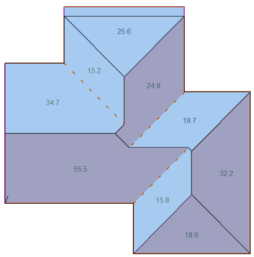
Roof/Wall Plane Areas
Inserts individual roof or wall plane areas. These will be printed on the roof/wall report.
Comments are closed.