Digitise2
Digitise Aerial Image – Slope Roof
The same process can be applied to aerial images. The three steps are:
1 Enable the image,
2 Scale the image and workspace, and
3 Start digitising.
Select Enable Underlay and then paste from the clipboard or open a saved file.
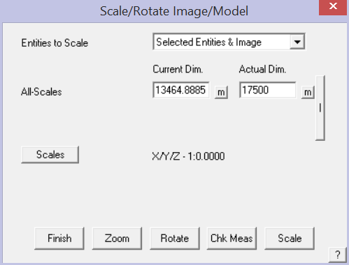
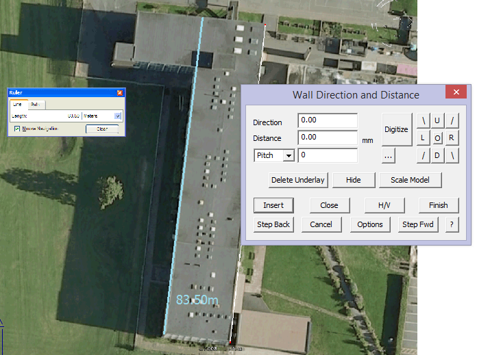
Scale Model using the overall dimension extracted from the aerial image provider’s tools, select each end of the length reference line (Current Dim.) and then type the actual measured length (Actual Dim.); hen select the [Scale ] button. The image is re-scaled. The software tries to do everything orthoganally so to set the overall measurement across the widest part of the building, hold down the Control (Ctrl) key to measure ‘off-grid’. More details on scaling and rotating here.
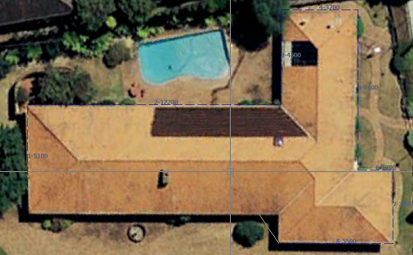
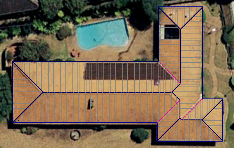
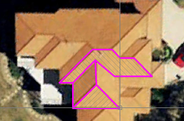
Now start digitising the perimeter, you are working at actual size.
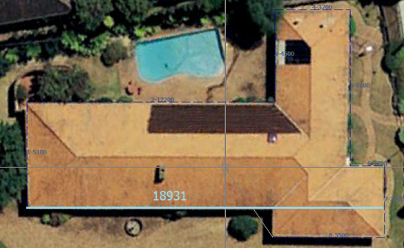
Digitise the perimeter and when you get to the penultimate corner, right click mouse [Cancel] and you will be prompted to close the outline.
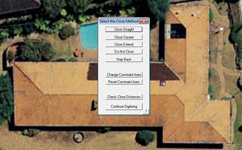
Typically you would select Close Square or simply type C for close.
The outline is closed out and then you are prompted for the details of the roof pitch and the overhangs etc.
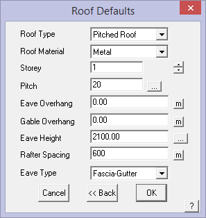
Set as required and select [OK].
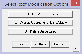
Add vertical features such as Gable Ends if you have any (this example does not) and select [Continue].
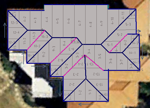
The 3D roof model is constructed. This is the quickest and easiest way to create accurate roof models that have regular roof geometry.
All the required AppliCad take-off functions will now work on this model for the most detailed and accurate client proposal.
This roof is complete then the image is turned off using the [Hide Image] button on the Track Outline dialog.
The 3D roof model is now displayed, ready for the rest of the checking and estimating process to be completed.
Digitise Aerial Image – Single Slope (Flat) Roof
The same process can be applied to aerial images. The three steps are:
1 Enable the image,
2 Scale the image and workspace, and
3 Start digitising.
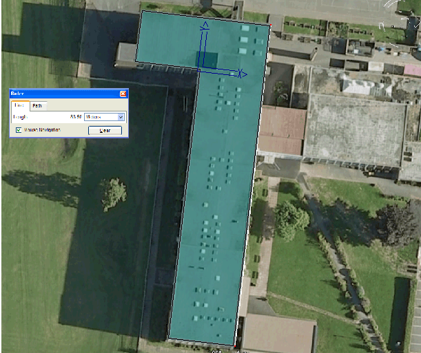
Select Enable Underlay and then paste from the clipboard or open a saved file.
Scale Model using the overall dimension extracted from the aerial image provider’s tools. The software tries to do everything orthoganally so to set the overall measurement across the widest part of the building, hold down the Control (Ctrl) key to measure ‘off-grid’. More details on scaling and rotating here.
Digitise the first line, again holding the Ctrl key to insert the line off-grid; then right click [Cancel] and select [Close]. This brings up the Close Method dialog which provides for the option to re-align the digitise axes with the last digitised line. Select the function [Align Axes with Last Line]. The CPL or Construction Plane is re-aligned and you may continue digitising.
Digitise the perimeter and when you get to the penultimate corner, right click mouse [Cancel] and you will be prompted to close the outline; select Close Square. The Roof Defaults dialog is displayed and you set the Roof type to be Single Slope and the pitch as required. In this case it is zero.
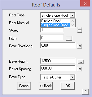
Select [OK] and you will be prompted for the pitching line. This roof is totally flat, so select [Continue].
And the job is complete. Notice the CPL icon is rotated and relocated. This occurred when we aligned the axes.
Set New Digitise/Trace Reference or Datum Point
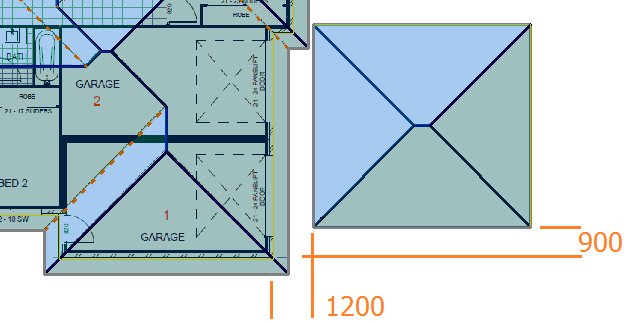
If you are tracking a subsequent roof outline (with an existing roof already on screen) and need to specify a start point, click the ‘o’ in the middle of the accelerator buttons:
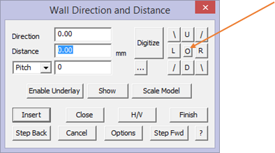
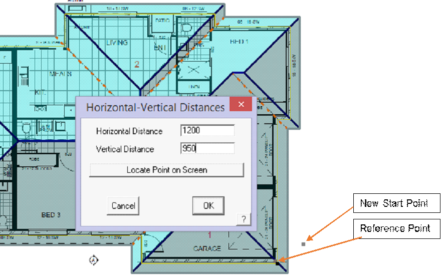
You will be prompted to locate a Reference Point. Determine where the reference point should be and if it is the corner of existing geometry, you can ‘Snap’ to it with the middle mouse button. This does not create a new point, but uses the existing point that defines the lines at that corner.
Type in the offset from the reference point to the new outline start point, (1200 over and 950 up), and when you start the new outline, this is the new start point.
User Tips when Digitising
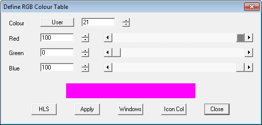
If you are digitising lots of aerial images or plans from PDF documents in 2D, you might like to change the line style so that your digitising progress is very easy to see. The line that is inserted by default (if you do not set the line type as you go) is line type None. So if you were to change a ‘None’ line to be bold and fat, you can easily see what has been digitised and what hasn’t. Use this example, under CAD > Defaults > Colour Table redefine a colour number to bright pink – let’s say colour number 21. Select Apply and Close.
Next, go to Set-Up > Preference Settings > Line Styles change the None line to the newly defined colour of bright pink colour 21 and also change the line weight to say 1.00 to make it bold.
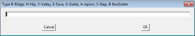
Then as you digitise using the Construct Roof > 2D Roof > Digitise Roof option, cancel the Line type definition box (shown below) by right clicking or selecting [Cancel] (which is the same thing) so that the line type is set to ‘None’, (you will then have to go back and manually select each line to redefine the line type) and the big fat pink line will be displayed instead of the regular line style for that line type.
You can very quickly see what you have completed during the process.
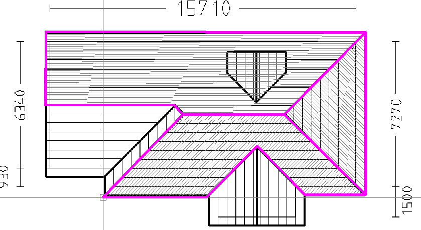
If you wish to keep this line style change, don’t forget to select File > Save Values and save the changes to the Values.def file (where these default settings are stored).
This works well for you both on images of planes clipped from a PDF as it does on images clipped from Google™, NearMaps™ or Bing™ or Acrobat Reader™.
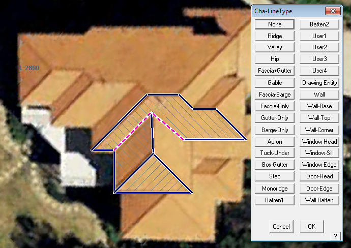
Once you have competed the digitising, you then use the Tools > Change Line Type function to set the line types in turn – ridges, hips and valleys etc. This is often seen as a lot quicker by some operators
Extract brilliant metal panel cutting lists directly from the clipped aerial image or the clipped PDF drawing (subject to site inspection of course) for roofing or wall cladding.
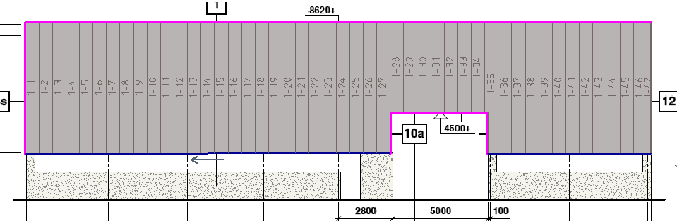
For walls, clip the image of the wall elevation:
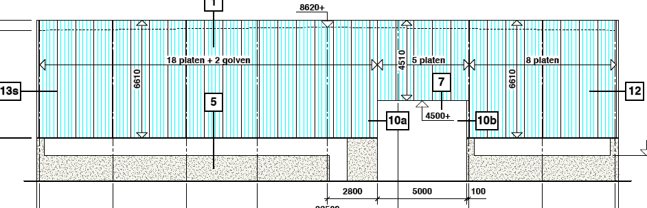
Digitise the wall (Walls > Draw Single Wall) and generate the wall panel cut list (requires AppliCad Roof Wizard module) using function Walls > Apply Wall Set-Up > Generate Wall Panels.
These functions will change the way you generate cutting lists in 2D – easy, quick and accurate (as accurate as the images permit).
Comments are closed.