CAD Insert Line
CAD > Insert > Line
The Line Insert command enables the Line Insert sub-menu which allows the insertion of free, constrained, horizontal, vertical, angled, parallel, chord, tangential and perpendicular lines. A stream of adjoining lines, a rectangle comprising four lines and a series of lines which describe a specified number of equi-angled sectors within a selected angle can also be inserted. Not all these options are available from the Pulldown Menu. For the rest of the options, turn on the right hand menu and go to CAD > Line.
This menu can span more than one screen as it is very long. At the bottom of each screen menu is a Next and Last option that should take you to the appropriate screen text menu.
Free
Allows the insertion of any number of adjoining lines by continual selection of point locations.
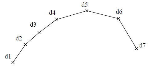
The first point location selected is the start of a line and the second point location selected is the end of that line. Further lines will be inserted for each consecutive point location selected, where the endpoint of the preceding line is the start of the next line. The Abort button aborts further adjoining line insertions and allows another line or series of adjoining lines to be freely inserted.
Horizontal
Allows the insertion of lines that are horizontal with respect to the current CPL (i.e. parallel to the x- axis).
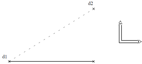
The start point of the line is selected first. A second point location is then selected which defines the length and direction of the line. The actual endpoint of the line is located at the intersection of a line projected from the start point parallel to the x-axis of the current CPL, and a line normal to that line which passes through the second point location.
Vertical
Allows the insertion of lines that are vertical with respect to the current CPL (i.e. parallel to the y-axis).
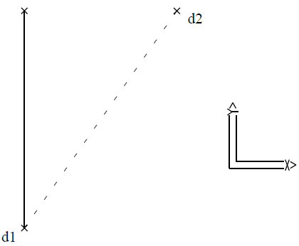
The startpoint of the line is selected first. A second point location is then selected which defines the length and direction of the line. The actual endpoint of the line is located at the intersection of a line projected from the start point parallel to the y-axis of the current CPL, and a line normal to that line which passes through the second point location.
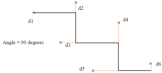
Angle
Allows the insertion of lines at a specified angle relative to a reference line.
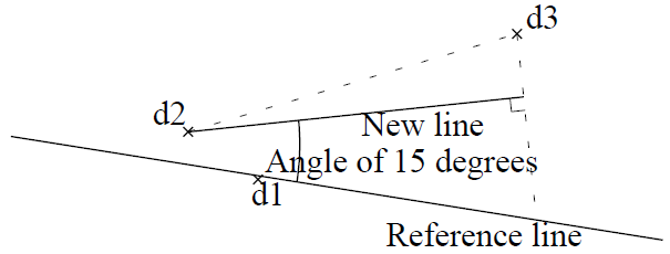
The reference line is selected and then the angle is specified. The angle specified is relative to the plane defined by the reference line endpoints and the startpoint of the new line. Its orientation is defined by the general direction of the new line relative to the reference line (i.e. start to end direction of new line).
The startpoint of the line is then selected (d2) and then a second point location is selected (d3) which defines the length and the general direction of the new line. The actual endpoint of that line will be located at the intersection of a line projected from the start point, at the specified angle, and a line normal to that line which passes through the second point location.
Constrained
Allows the insertion of any number of adjoining lines at a specified angle or multiple of that angle relative to the X-Y plane of the current CPL by continual selection of point locations.
The angle is specified followed by the selection of the point locations. The first point location selected is the start of a line and the second point location selected defines the length and general direction of the line. The actual endpoint of that line will be located at the intersection of a line projected from the start point at the specified angle or multiple of that angle and a line normal to that line which passes through the second point location selected.
Further lines will be inserted for each consecutive point location selected, where the endpoint of the preceding line is the start of the next line.
Rectangle
Allows the insertion of four lines which form a rectangle by defining two diagonal corners.
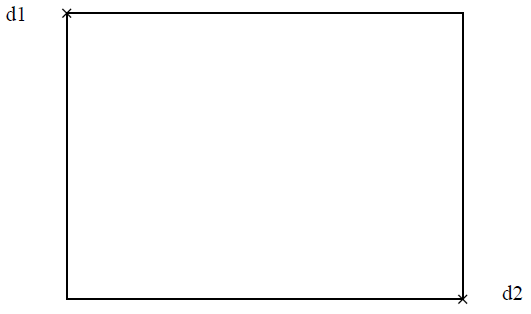
A point location is selected defining one corner of the rectangle. A rectangular window then displays with its diagonal corners being the first point location and the cursor. By moving the cursor, the rectangular window continually stretches allowing visualisation of the rectangle prior to selecting the opposite corner position. Four lines are then inserted forming a rectangle with the selected corner positions.
Chord
Allows the insertion of lines as chords to a reference circle. The length of the chord is specified, followed by the selection of the reference circle.
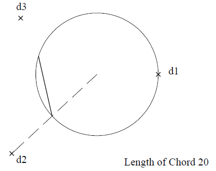
The start location of the chord is then selected on the circumference of the reference circle and then a location is selected which defines the direction of the chord. The chord is then inserted with the specified length and its end location exactly on the circumference. If the start location is not exactly on the circumference, the actual start location is the intersection of the radial line passing through the selected location with the circumference.
An arc may be selected as a reference with this command but it will be regarded as a circle, therefore, the chord will be calculated for insertion using the imaginary circle and its start and end locations may not be situated on the arc.
T-Cir-Cir
Allows the insertion of a line that is tangential to two reference circles.
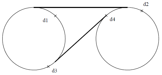
The reference circles are selected near the approximate tangency points and the line is inserted tangential to both circles between their respective tangency points near the approximate tangency points selected.
Arcs may be selected as references with this command, but they will be regarded as circles. The tangency points for inserting the line are calculated using the imaginary circle and therefore the start and end locations may not be situated on those arcs themselves.
T-Cir-Lin
Allows the insertion of a line that is tangential to a reference circle and at a specified angle to a reference line.
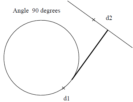
The reference circle is selected near the approximate tangency point, followed by the selection of the reference line at the appropriate location relative to the tangency point. The angle, between the reference line and the line tangential to the reference circle, is then specified. The line is then inserted from the tangency point on the reference circle nearest to the approximate tangency point selected to its point of intersection with the reference line at the specified angle to that line.
An arc may be selected as a reference with this command, but it will be regarded as a circle. The tangency point for inserting the line is calculated using the imaginary circle and therefore that endpoint may not be situated on the arc. This command regards the reference line as having infinite endpoint extensions. Therefore, the line inserted may have its endpoint lying on the extension of this line.
Comments are closed.